Like the title says, it started on this thread but I decided to start a dedicated one. Parts Massey 1450
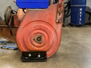
Looking for mounting ideas & pics.
Looking for mounting ideas & pics.

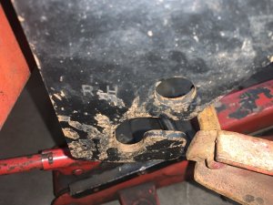
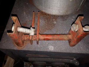
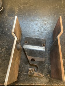
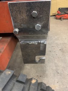
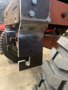
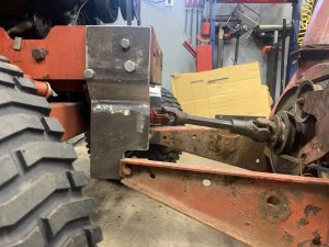
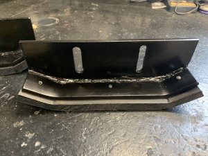
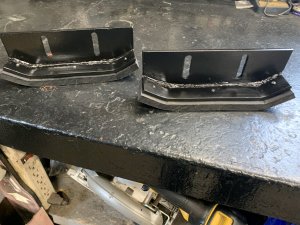
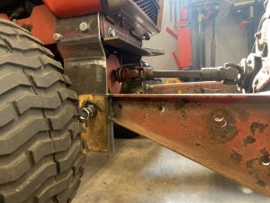
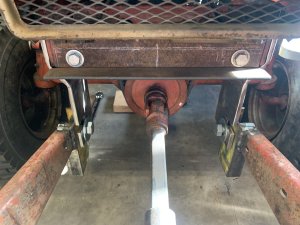
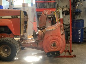
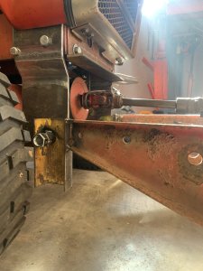
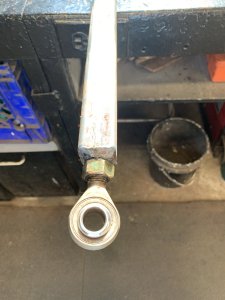
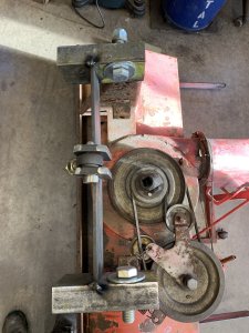
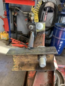
Nike's, Sketchers ????Not much to report lately, I did manage to get a new set of shoes fabbed up. I have the measurements just have to make up the pieces for the blower mods then I’ll do the lift arm.
Come on Kenny obviously “snow shoes” bahahaNike's, Sketchers ????
Nope doing that next week on my vacation. I’ll let you know when I do Noel So you can come up. Trying to do most of the smaller pieces and fab work in my spare time at work to keep the Home time hours down lol.Ya must of been busy cutting and splitting your wood.
Noel
Nope I start vacation Wednesday morning, off for 12 days.Thought you were doing your wood this week. I'm now where near done of my yet.
Noel