Back on the powered lawn roller idea.

jdcrawler

Tractorologist
Member
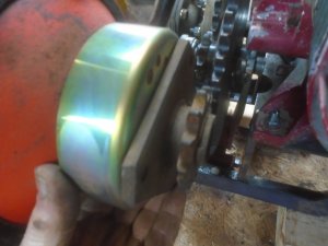
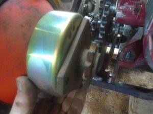
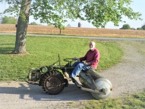
Some of you may remember a few years ago when I mounted the drum from my lawn roller onto the back of a Ridemaster tractor. The roller set up this way was much more practical to use with me riding on it than it was when being pulled behind the R/T tractor. It was easier to move around things like trees and a lot easier when backing up. I really liked the function of the design.

However .. there was one drawback. The Ridemaster just didn't have enough horsepower.
The roller is 5 foot long and 2 foot diameter and weighs around 970 pounds when full of water. The Ridemaster would move it alright on level ground but could hardly make it up any incline at all.
1.JPG


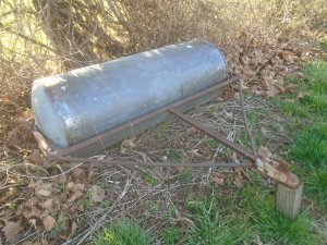
I went ahead and used the powered roller to pack down the gravel that I had put down in front of the garage, then I removed the roller drum from the Ridemaster and mounted the hitch back on it so it could be pulled behind the tractor again.
DSC06010.JPG


After using it as a pull behind roller again for awhile, I decided that I really liked it better when it was self powered.
Of course I could put it back on the Ridemaster and then put a bigger engine on it too but that would rune a restorable Ridemaster that is complete.

So I looked thru my stuff to see what I could use to power the roller.
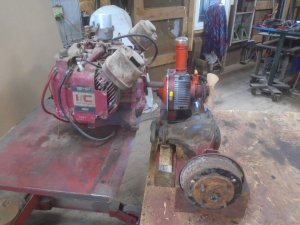
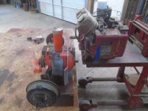
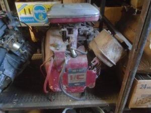
I have this 18 HP B&S twin cylinder engine that should give it enough horsepower.
DSC06019.JPG


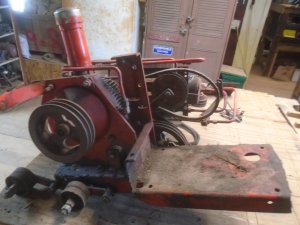
And this hydrostatic drive pump for forward and reverse.
DSC06012.JPG


I have a new pair of 8.00x16 tractor tires that my son bought last year but never used.
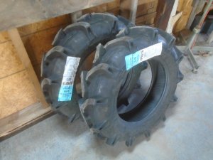
DSC06020.JPG

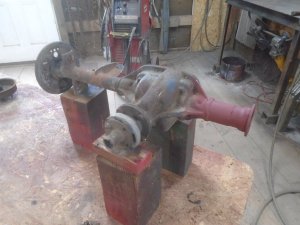
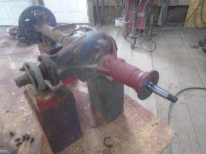
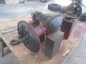
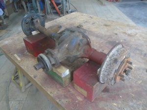
I also have a rear axle out of a mid 60's Cushman 3-wheel Truckster.
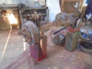
DSC06027.JPG


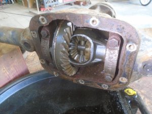
Pulling the brake drums off, there aren't any brake shoes or wheel cylinders and the axle oil seals are leaking bad.
These parts are available but they are pricey. I'm not going to bother with replacing the brakes because the hydrostatic unit acts as a braking unit also. I am going to replace the oil seals and I intend to mount a 4 inch diameter band brake on the drive side of the hydrostatic pump for a parking brake ( this could also be used as a regular stopping brake ).
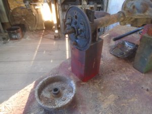
DSC06028.JPG


The gears inside look really good.

DSC06021.JPG


I like the design of the Ridemaster tractor with the engine mounted right on the front drive wheels and with them being able to turn so far around.
I want to build this engine and drive unit with the same design. The Cushman axle is about 42 inch wide and obviously I'm not going to be able to get the wheels as close together as they are on the Ridemaster but I can shorten it up some.
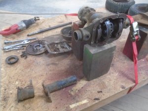
So I have removed the axle shaft from the left side.
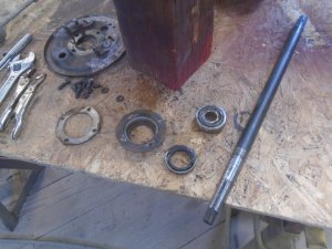
DSC06023.JPG


Measuring the housing, it looks like I can shorten it about 8 or maybe 9 inches. That would make the wheel spacing about the same as most 2-wheel walk behind tractors and I can make the axle so it pivots in the center for turning.
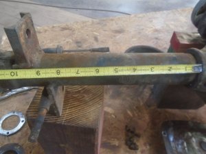
DSC06031.JPG
 
Last edited:
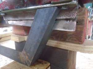
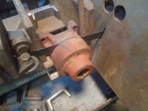
A section of the tube is cut off the left side of the axle housing.

DSC06032.JPG


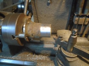
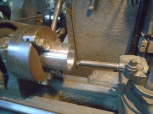
The mounting bracket is cut off the outer part and it is chucked up in the lathe to cut the welds off the tube.

DSC06033.JPG


Then a sleeve is machined to fit over the axle housing tube.

DSC06034.JPG


These two parts are fit back onto the axle housing and welded in place.

DSC06035.JPG


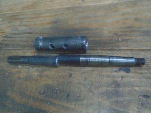
A section is then cut out of the axle shaft and a sleeve is machined out to fit the two pieces into.

DSC06036.JPG


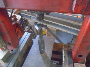
The sleeve is machined tight enough so that the axle shaft can be pressed into it.

DSC06038.JPG


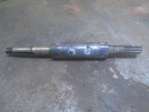
Then it is welded together.

DSC06040.JPG


The axle shaft is fit into the housing and the outer bearing is installed.

DSC06041.JPG


The backing plate is fit onto the axle housing.
I ordered a pair of grease seals from Napa and they will be in tomorrow.
When the hubs and brake drums are put back on, the axle will be about 34 inches wide.

DSC06042.JPG
 
The grease seals are installed in the ends of the axle housing and the hubs are set on temporarily. I don't have the rims for this yet and when I get them, I'll have to drill the hubs out to whatever lug pattern the rims are.

DSC06043.JPG


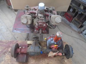
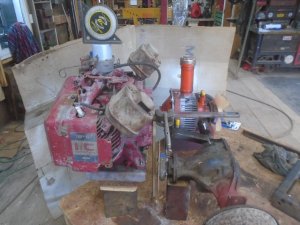
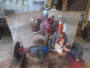
Figuring out where the hydro and engine need to be in relation to the axle. The engine will sit out in front of the axle to clear the drive sprocket that will be mounted on the front of the axle.
The piece of blue tape on the axle is the center of the axle.

DSC06048.JPG


Side view from the left. Setting the engine in front of the axle lets me keep it as low as I can.

DSC06049.JPG


Side view from the right.
The piece of blue tape on the side of the engine is about where the outside of the tire will be.
Only about 2/3 of the engine will stick out past the tires.

DSC06046.JPG


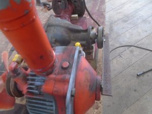
A piece of angle iron is bolted onto the front of the axle to to line the hydro up.

DSC06059.JPG


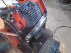
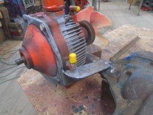
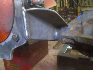
Mounting brackets are made up and tack welded to the right side.

DSC06054.JPG


Then the mounting bracket is fitted to the other side and welded in place.

DSC06055.JPG

DSC06058.JPG


The mounting brackets on the right side are finish welded.

DSC06060.JPG

DSC06057.JPG
 
Lining the engine up.

DSC06070.JPG


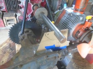
It is inline with the center of the axle. I don't have the big sprocket that will fit on the axle yet so I'm using a cardboard template to judge the clearance for the sprocket.

DSC06071.JPG


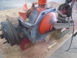
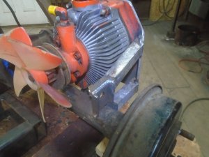
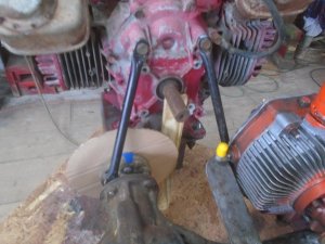
The first support brackets are made up and installed between the engine and the axle.

DSC06072.JPG

DSC06073.JPG


The mounting brackets for the plate that the engine is bolted onto will be made out of angle iron. This is the one for the right side.

DSC06074.JPG


Here is how it fits to the engine mounting plate.

DSC06075.JPG


This is the one on the other side.

DSC06078.JPG


The engine weighs 70 pounds and with it mounted out in front of the axle, I need to put a counter weight behind the axle.
I have several 1x2-1/2 solid steel bars that weigh a little over 10 pounds each.
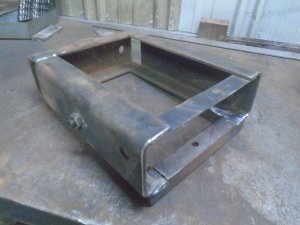
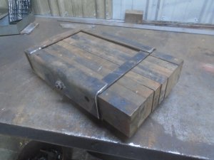
This is box that I made up to hold 8 of those steel bars.

DSC06051.JPG


The bars slide into it and are held in place by the set screw on the side being tightened up against them.

DSC06052.JPG


This box fits on the other end of the angle iron brackets that hold the engine.

DSC06080.JPG
 
OOPS !

The sprocket for the front of the axle arrived yesterday and I decided to put it on today. Before I do that though, I need to put a new grease seal in the input shaft housing so I started working on that first. That was when I found out that there isn't anything holding the driveshaft mounting flange onto the axle input shaft and it can slide right off !

Any rear axle that I have ever worked on has always had the drive shaft U-joint mount fastened onto the the axle input shaft. If I had realized that this axle did not have the driveshaft mount bolted on before I welded the engine mounting plate on, I would have positioned the engine a little farther forward to leave me more room between it and the front of the axle.

Fortunately, there is enough room so that I can remove the driveshaft mount but only if the sprocket is not bolted to it because the sprocket hits the back of the engine.

DSC06092.JPG

DSC06089.JPG


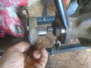
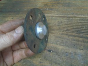
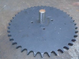
The tail end of the driveshaft was still bolted onto the mounting flange on the axle. The sprocket has a 3/4 inch diameter hole in the center so I turned down a piece of aluminum so it fit into the end of the driveshaft and left a 3/4 inch diameter stub sticking out.

DSC06086.JPG


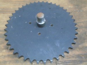
This fits into the center hole in the sprocket and I use a transfer punch to mark where to drill the mounting holes in the sprocket.

DSC06087.JPG


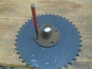
After the mounting holes are drilled, I press a piece of 3/4 inch steel rod into the center of the sprocket. This steel rod is welded to the sprocket on the back side.

DSC06094.JPG


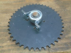
A spacer is made up and slid over the rod.

DSC06096.JPG


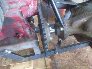
Then a pillow-block bearing is slid onto it.

DSC06097.JPG


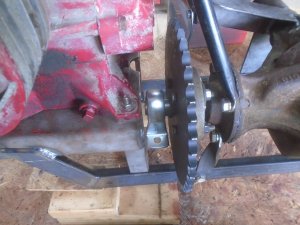
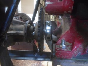
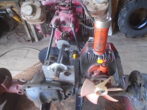
There is just enough room to mount the sprocket onto the driveshaft flange.
Obviously I can't weld in a bracket for the bearing to bolt to because that would be in the way of sliding the driveshaft flange off the axle.

DSC06098.JPG


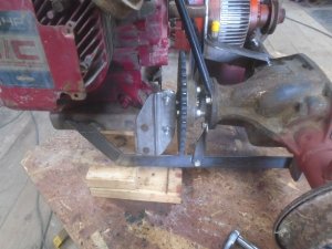
So I bolted a piece of re-enforced, 3/16 inch thick flat steel onto the side of the engine mount.

DSC06099.JPG


The pillow-block bearing is then bolted to the back side of this flat plate.

DSC06100.JPG
 
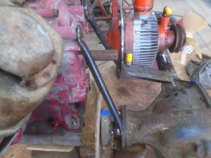
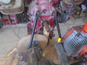
Along with these two upper tubuler brackets that go from the back of the engine down to the axle.

DSC06072.JPG


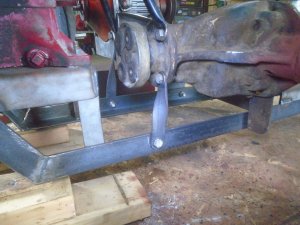
There are two strap brackets going from the frame up to the axle so that the front of the axle is held in place between the four brackets.

DSC06084.JPG


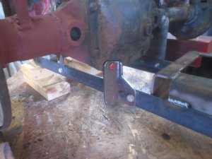
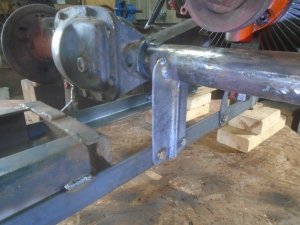
On the rear left side of the axle is an angle iron bracket that bolts to the back of the axle housing and is fastened to the frame with two bolts so it cant rock back and forth.

DSC06083.JPG


On the right side, a flat steel bracket is welded to the axle housing and the frame is fastened to it with two bolts also.
With the six mounting brackets holding the axle and frame together, they are very solidly fastened together.
This mounting arrangement also allows the axle to be unbolted and removed from the frame if needed.

DSC06082.JPG
 
There are guys that can take the RPM's of the engine, the gear ratio of the axle, the outside diameter of the tires and the number of teeth on the sprockets and figure out just how fast this thing will be going.
..... I am not one of those guys. .....

If I remember right, the Cushman Trucksters could run about 50 MPH with tires that were only 15 inch outside diameter. That tells me that the gearing is high in the rear axle.
I'm using tires that are 29-1/2 inch outside diameter so I'm going to have to gear this way down and I don't think the difference between the small sprocket on the hydrostat transmission and the larger sprocket on the axle is going to be anywhere near enough gear reduction.

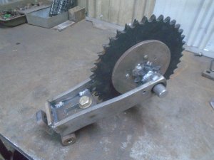
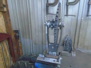
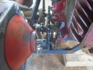
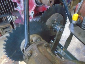
So I have built up another an intermediate hub with a small and large sprocket. This is mounted to a bracket that can pivot side to side and also move up or down to adjust the tension on the chains.

DSC06121.JPG


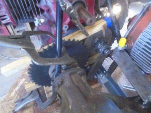
Two pieces of wood are used to line up this sprocket with the one on the axle. A short piece of angle iron is bolted to the lower side of the frame so I can tack weld mounting tabs onto the angle iron.

DSC06122.JPG


The assemble is removed and clamped in the vice to finish the welding.

DSC06123.JPG


The sprocket assembly is bolted back onto the frame with the small sprocket lining up with the sprocket on the axle.

DSC06124.JPG


This intermediate sprocket assembly can rotate out to set the chain tension to the axle and it can slide up or down to set the chain tension to the transmission.
The large sprocket is bolted onto the intermediate hub so it or the sprocket on the axle can be changed to adjust the gearing up or down.

DSC06125.JPG


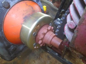
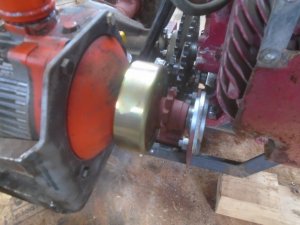
The small sprocket is machined out to fit onto the transmission.

DSC06127.JPG


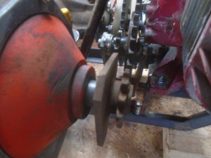
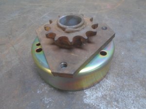
A drum for a band brake will be bolted to the triangular flange on this sprocket.

DSC06128.JPG


It will fit onto the transmission like this.

DSC06129.JPG


........................................ I have been going over a few ideas of how to make this drive assembly turn for steering like the motor and transmissions on the Bolens Ridemaster's do. I have decided that the easiest - and what would also look the best - would be to use the upper frame tube and steering from a Ridemaster.
My problem is that I do not have a Ridemaster frame. .................................

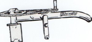
So I'm hoping that maybe someone here has an old rusty or damaged Ridemaster that they would be willing to sell the tube frame and steering off of. This would be too awkward and heavy to ship so it would need to be within reasonable driving distance of Madison, Indiana so I could pick it up.

Here is a sketch of what I would need.

upper Ridemaster frame & steering.jpg
 
Last edited:
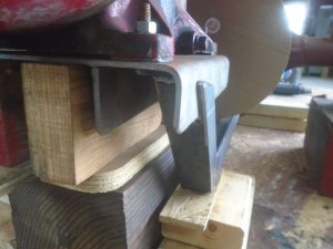
.Originally, I had intended to mount the brake drum behind the triangular flange like this.

DSC06129.JPG


I decided to mount it in front of the flange like this. It looks much more professional this way.
The shaft on the hydro unit only sticks out about an inch and the sprocket sticks out more than that. So I added a shaft to the front of the sprocket for a bearing to fit onto.

DSC06130.JPG


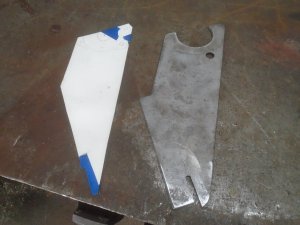
A pattern is made up from cardboard for the mounting bracket for the bearing. It is traced onto a piece of flat steel and cut out.

DSC06131.JPG


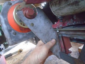
Checking the fit of the mounting bracket.

DSC06132.JPG


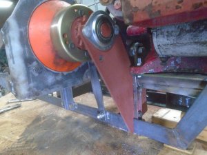
The bolt holes are drilled into it and it is bolted onto the frame with the bearing bolted to it.

DSC06133.JPG

DSC06134.JPG
 
Working on the final stage of connecting the engine to the hydro unit.
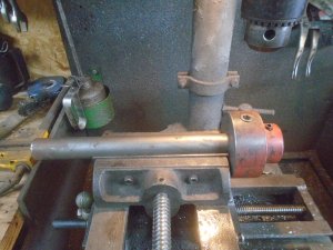
The engine has a keyed, 1 inch diameter output shaft and I just happen to have this piece that has a keyed, 1 inch hole in one end and a drive shaft flange on the other end.
I'm going to use a 1 inch diameter shaft coming off the engine so I cut the driveshaft flange off this piece.

DSC06135.JPG


It is attached to the 1 inch shaft with a countersunk 3/8 allen head bolt threaded into it.

DSC06136.JPG


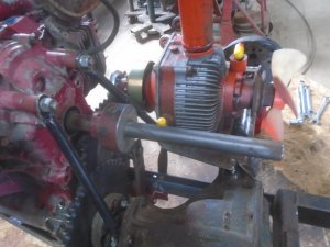
This then fits onto the engine shaft.

DSC06137.JPG


Making up a cardboard template for the bracket to hold the support bearing.

DSC06138.JPG


The bracket is cut out and welded onto the top of the axle housing.

DSC06139.JPG


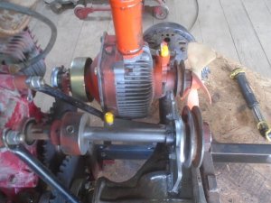
The drive pulley for the engine is fit onto the end of this shaft.

DSC06143.JPG


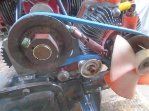
The engine is connected to the hydro unit with a 1/2 inch wide V-belt.

DSC06144.JPG


........ At this point, this drive unit is ready to start attaching it to the roller but I can't start on that until until I figure out what I'm going to do about the steering ? So this project has come to a halt for the time being. That really isn't a problem because the clay ground around here has already gotten too hard to do anything with a roller this spring.

In the mean time, I'm going to start working on a project that I have been collecting parts for, for a very long time.
It is a Ford model-T tractor conversion.
 
Back
Top