New project

jdcrawler

Tractorologist
Senior Member
Member
This post is going to start out running all over the place so pay attention or you may get lost .......

The model-T is up to as far as I'm going to take it and I'm just waiting on some parts before I can get the engine running.
Once the engine is running .. then I am going to put it up for sale so then I'll be waiting some more until it sells ( and that may just take awhile ).

So ... my next big project is to finish a 1947 Plymouth convertible that I bought way back in 1968.
I paid $ 35 for it at that time. It didn't run and when you opened the door you could see the grass that was under it because the floor was all rotted out of it.
Unfortunately I do not have any photos of what it looked like then but this is what it looked like in 1972. We lived in Traverse City, Michigan and that little girl standing beside it is 53 years old now.

Behind it is my 64 Jeep woody. I made the top from the back of a VW bus and the windows for the doors came out of a 57 Plymouth two door hardtop.
I used the Plymouth mechanism in the wood doors so I could crank the windows up and down. The Jeep had a turbocharged 215 CID Aluminum V-8 engine out of a 1963 Olds Cutlass.
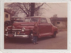
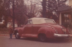
1972  TC.jpg

1972 -.jpg


We drove 47 for our vacation to Florida in 1973 and this photo was taken at Bradenton Beach.
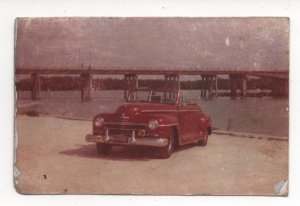
1973 Florida.jpg


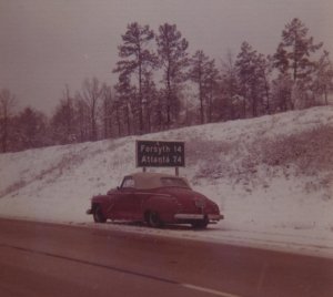
Heading home from that vacation we ran into snow and I had to pull over and take this photo south of Atlanta.
73 vacation.jpg


We moved to Goshen Indiana in 1974 and I drove the car for a couple of years more. It still had the old flathead six in it and it started using oil so I decided it was time to make a street rod out of it. The old six cylinder came out and that was the last that the car was ever on the road.

I was working a minimum 50 week working on the Plymouth off and on. The years went by and I built up and drove other old cars and motorcycles and the Plymouth kept being being pushed farther down the priority list.
Over the years, I've had several old cars that I finished and drove for awhile. The oldest was a 1936 Plymouth 4-door Special Deluxe and the newest was a 1960 Chevy El Camino. I also built a few street rods up for other people.

As time went by we would get hard up for money or I would se something else that I wanted more then what I was driving so I would sell the car I was driving at that time.
That is the only reason that I still have this 47 Plymouth. All those years, I had never gotten it completed enough to where it was worth anything so it never went up for sale.
I did have it running for a little while in the late 80's with a 350 Chevy engine in it but it wasn't anywhere close to being able to put on the street.

The 350 Chevy engine that was in it then ended up being the first engine in my 1959 Chevy truck when I first put the truck on the road in 1995. I have been driving the truck regularly ever since 95 and it hasn't gotten sold simple because it has always been worth more to me then what anyone would have been willing to pay for it.

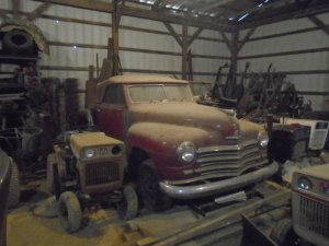
So ... here we are in March of 2021 and the 47 Plymouth has been sitting in storage, with no engine in it since 1995.
This is what it looked like yesterday sitting in the back of my son's garage.
March-3, 2021.JPG


That red convertible top was put on new in the early 90's but I'm sure it would brake into little tiny pieces if I tried to raise it up now.
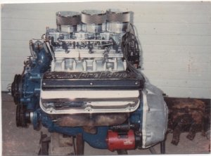
Since I stole the Chevy engine out of it I have put this engine together to go in it instead.
57 Hemi 354.jpg

This is another 1957 Chrysler 354 Hemi with Holly 2-berral, tripower carburetors. This photo shows a 3-speed transmission on it but it has since had a 350 Chevy automatic adapted to it to go into the Plymouth.

.......................... Okay .. now, I cant bring this over to my garage yet because the model-T is still sitting in the spot where I need to put the 47 Plymouth to work on it.
Also .. there is no point in starting on the Plymouth until after the model-T is sold because I won't have enough money to work on it until then.


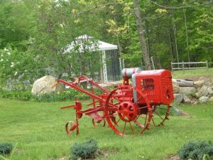
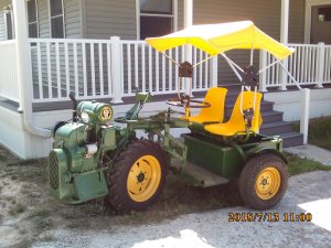
Some of you will remember this cart that I had built out of an old Bolens Ridemaster. We used this a lot when we tractor shows and that trailer bed on the back sure came in handy.
I sold this but I would still like to have something like this to run around on at the shows.
B9.JPG


I have been to a few tractor shows down here and I've been using the R/T tractor to run around on. It works out al right but I miss not having the trailer box and I can't take a rider along with me on the R/T.

So while I'm waiting on parts for the model-T and then waiting for it to sell, I'm going to build another 2 - person cart with a trailer box on it.
This is a 1939 Standard Twin Viking model ( originally a 2-wheel garden tractor ).
I got this from my good friend, Jerome Wilber and someone had converted it to a riding tractor with rear wheel steering.
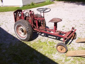
21.JPG


I also got this garden trailer box from Jerome at the same time.
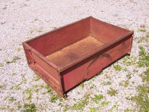
8.JPG
 
Last edited:
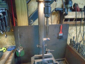
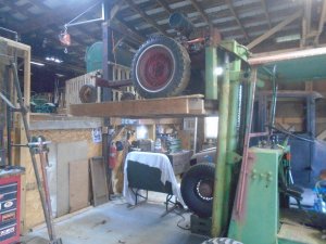
I've had the Viking tractor stored up in the loft of my garage and I spent about an hour moving things around so I could get it out.
I use my forklift for my elevator to access the loft.

DSC03600.JPG


This is what a 1939 Viking tractor looked like from the factory.
These tractors were started with a hand crank but I have put a starter / generator on mine for electric start.

Viking 1939.jpg


The only difference between a Standard Twin garden tractor and the Viking garden tractor is that the Viking had the sheet metal for the grille, hood and side panels.
The engine on the Standard Twin was fully exposed.

I know you could get steel or rubber tires on the Standard Twin but I do not know if the Viking was available with rubber tires as an option.
Either way, my tractor originally had steel wheels like in the photo.
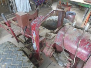
Some one has cut the steel wheels off and put regular 15 inch car wheels on it.
Notice .. there aren't any lug bolts holding these car wheels on.

DSC03606.JPG


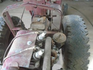
They are welded to what is left of the spokes from the old steel wheels.

DSC03605.JPG


I have a pair of old 16 inch Kelsey Hays wire wheels that have a lot of sentimental value to me and I have been dragging them around with me ever since 1963.
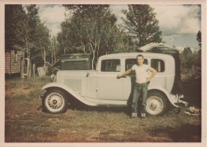
These wheels came off the back of my older brother's 1932 ford.
You can see them in this photo with stainless trim rings on them.

Jan & 1932 Ford.jpg


Jan ( my brother ) was 10 years older then me and he had bought this car when he was a senior in high school in 1954. He was killed in the family car in February of 1963 when he was hit head on by a drunk driver. His 32 ended up being sold and the guy that bought it didn't want the rear wheels because they are split rim clincher wheels. Back then we had several old Ford wheels laying around so dad took the Kelsey Hays wheels off and put a pair of regular Ford wire wheels on.

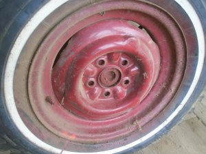
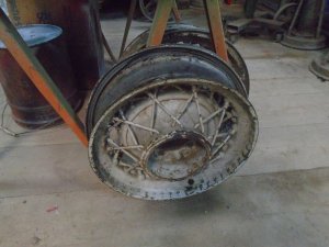
Here are those wheels with the white paint still on them.
You can see the marks where the paint has been scraped off around the inside of the rim from removing the trim rims.
I still have the trim rims but they're still packed away some place.

DSC03604.JPG


All I have of the Viking sheet metal is the formed rear hood brace and the front grille panel.
Because I was missing the hood and both side panels, I had originally planned on selling the rear hood brace and the grille to someone that needed them to restore their Viking tractor.
Since then I have decided to go ahead and use the Viking sheet metal and that is probably going to get some one upset with me.
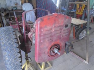
This grille is in very good condition and I am going to go and cut part of it away for clearance for the starter / generator.

I have taken the gas tank off and bolted the rear hood brace in place.

DSC03608.JPG


The original carburetor that was in the box of parts that I got with this tractor was missing some parts. Since I wasn't going to restore the tractor, I adapted a more modern Briggs & Stratton carburetor to it.
As you can see, this carburetor sticks out past the side of the rear hood brace. So I'm only going to put the top hood panel on it and leave the sides open.

DSC03609.JPG


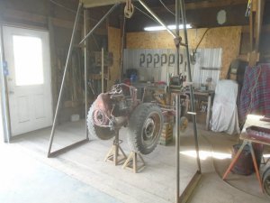
I'm already getting a kink in my back from bending over while working on this so I hauled it up in the air and set it on stands.

DSC03610.JPG


Here is that nice grille panel fastened in place with the lower right corner chopped off.

DSC03611.JPG
 
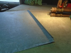
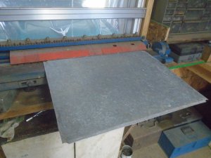
I'm going to use this old piece of galvanized metal to make the hood.
Here I have bent one edge up on it on my smaller brake.

DSC03615.JPG


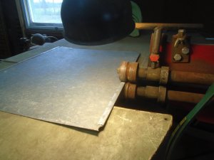
Then I run it thru the roller to flatten that edge down.

DSC03617.JPG


Ready to bend up the opposite edge.
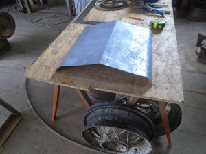
All four sides have been bent over to create smooth rounded edges with double metal thickness around the edges.

DSC03613.JPG


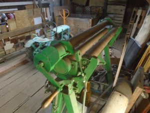
Back in the late 80's, I built this 3-roller sheet metal roller.

DSC03620.JPG


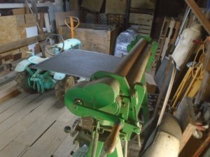
The sheet metal is clamped between the first two rollers and the back roller is moved forward or backward to control the amount of the curve.
For this piece, the back roller is drawn up tight to make the radius of the curve as small as I can get it.

DSC03619.JPG


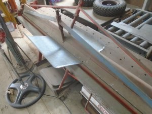
The piece is put in my larger brake and a slight bend is put into the center of it.

DSC03622.JPG


Here is how the hood looks so far.

DSC03623.JPG


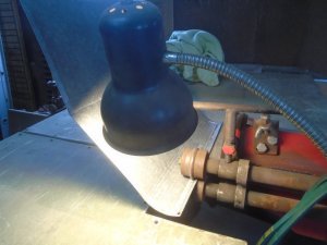
I'm rolling a bead along the two side edges to make them a little more ridged.

DSC03625.JPG


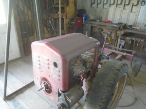
The outside of the hood is primed and mounted on the tractor.

DSC03627.JPG


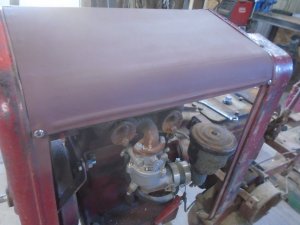
Here is a closer look at the beaded edge.

DSC03633.JPG
 
Last edited:
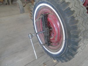
A long time ago I had modified a puller so that the arms were extended out farther to get the claws around bigger items.
That modified puller has come in quite handy over the years and I had to use it again to pull the wheel hubs off the tractor spindles.

DSC03630.JPG


Here are the wheels with the hubs welded to the inside of them.

DSC03631.JPG


I cut the hub spokes loose from the wheels with my torch.
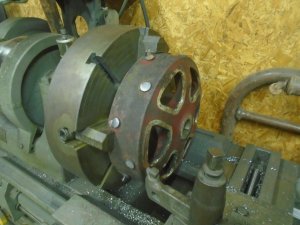
Then I took the hubs out to my son's garage and put them up on his big lathe to turn the spoke stubs down.
I was hoping be able to grip these hubs on the inside but the inside of them is tapered so I had to grip them on the outside.
This only let me machine off about two thirds of the back spokes off and I'll grind the rest of them off.

DSC03634.JPG


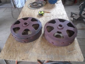
The face of the hubs are machined flat with a boss extending out about 1/4 inch in the center.
I have a pair of wheel adapters ordered that have the wheel studs at the correct spacing to fit my wire wheels.
I will turn down a spacer that the inside will fit over the boss on the hubs and outside will fit inside the wheel adapters.
This will center the adapters on the hubs and I can then drill and tap the holes to bolt the adapters onto the hubs.

DSC03636.JPG


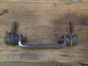
That's as far as I can go on the hubs so I'm going to work on the pivot mount to go between the tractor and the trailer bed.
This is a part left over from building the Centaur tractor and it is just the right shape and size for making the front part of the pivot mount.
Here I'm drilling a tapered hole into each end.

DSC03637.JPG


These tapered holes are for mounting two tie-rod ends to it.

DSC03638.JPG


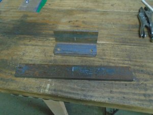
Next I need two angle brackets that will bolt onto two flat pieces of steel that will later be welded to the underside of the trailer.
This is one set.

DSC03639.JPG


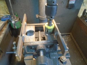
A 2 inch diameter hole is drilled into each of the angle pieces.

DSC03640.JPG


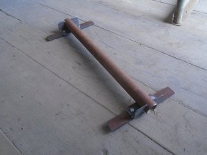
These two brackets are mounted onto a 27 inch long piece of steel pipe.

DSC03641.JPG


The bracket for the tie-rod ends is welded to the end of a piece of 1-1/2 inch solid rod.
This rod is slid into the pipe and washers on each end will keep in place.
The front washer is welded on the rod and the washers on the other end will be held in place by a 5/16 diameter pin thru the rod.

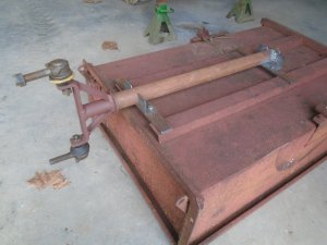
This assemble will later be welded onto the underside of the trailer.
The rear angle bracket is already welded to the end of the pipe but the other angle bracket won't be welded in place until I determine how far I want this shaft to stick out past the front of the trailer.

The tie-rod ends will allow the trailer to turn left and right behind the tractor and the pipe will be able to rotate on the 1-1/5 inch rod for going over uneven ground.
The two tie-rods being spread apart and the long pipe will keep the trailer and tractor in line so they don't sag in the middle.

DSC03642.JPG
 
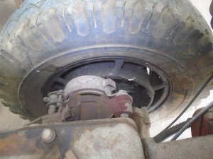
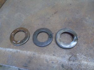
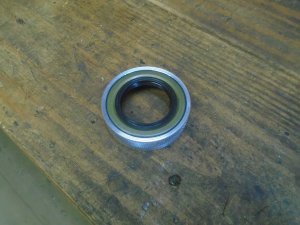
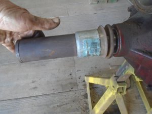
Both of the axle grease seals were leaking on the tractor so punched a hole in them and pulled them out.
There are two pieces of metal with a cork ring in between them to form the seal.

DSC03648.JPG


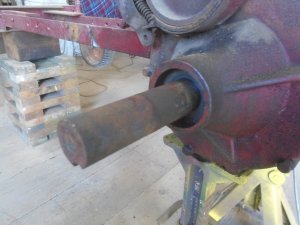
The axle shaft is 1.375 diameter and the counter bore in the housing is 2.350 diameter.

DSC03649.JPG


Lots of seals are 1.375 on the inside but none of them are 2.350 on the outside.
The closest I could get was 2.125 diameter on the outside so I need to make spacer rings to go into the counter bore in the housings.
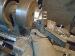
Here I'm turning down the outside of a piece of aluminum to the 2.350 diameter.

DSC03652.JPG


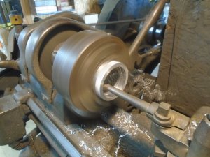
Then I turn the inside out to the 2.125 diameter.

DSC03657.JPG


The grease seal is then pressed into the aluminum sleeve.
I'm using a double lip seal.

DSC03659.JPG


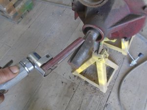
The edges of the keyway on the axle shafts are sharp so I used a small belt sander to put a beveled edge on them so they won't damage the seal.

DSC03658.JPG


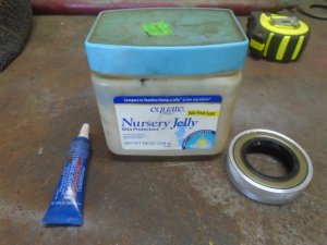
The axle shaft will be coated with Vaseline before I slide the seal up onto it.
A long time ago, I had asked Marie to get a jar of Vaseline for me when she went to the store.
She brought back this jar with the baby fresh sent.
Now, every time I use this on a car or tractor, it smells like a freshly powered baby for awhile.

DSC03660.JPG


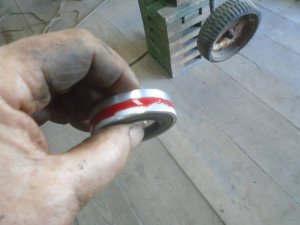
I want to glue these aluminum spacer rings into the counter bore so I knurled the outside of the aluminum ring to give it a rough surface for the lock-tight to grip to.
A bead of lock-tight is put around the outside of the spacer ring.

DSC03663.JPG


The seals are pressed into the counter bore with a hammer, using a big washer and my home made long seal installation tool.

DSC03661.JPG


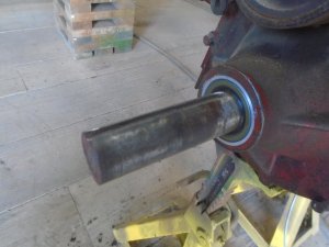
Here is how the axle looks now with it's new grease seal installed.

DSC03662.JPG
 
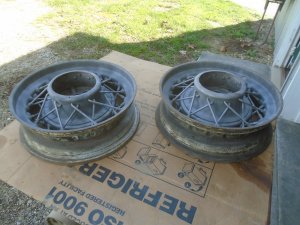
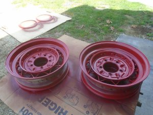
Got the wire wheels sand blasted today.

DSC03670.JPG


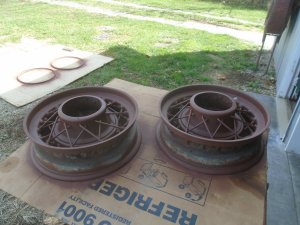
Primed. The clincher rims are on the piece of cardboard in the background.

DSC03671.JPG


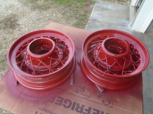
The back of the wheels are painted.

DSC03672.JPG


And the fronts are finished.
It's always a challenge to get nice even coats of paint on wheels like this with out any dry spots or runs.
The spokes have to be sprayed at several different angles to get the paint all the way around them.
The upper spokes themselves block the paint from getting on areas of the spokes that are crossing underneath them.
Both the upper and lower spokes block the paint from getting on areas of the center hub.

The spokes have to be sprayed more than a dozen times on both the front side and the back side.
Each pass is sprayed at a slightly different angle each time to get all around the spokes and in between them and under them to the cover the surface of the hub.
The color is Rust-Oleum, Colonial Red. This is a darker red than the more common Farmall red that you see at the tractor shows.

DSC03674.JPG


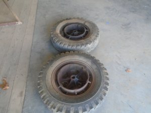
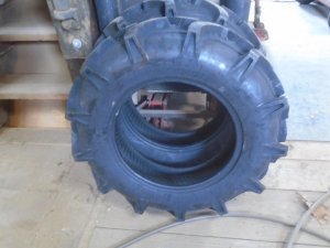
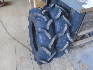
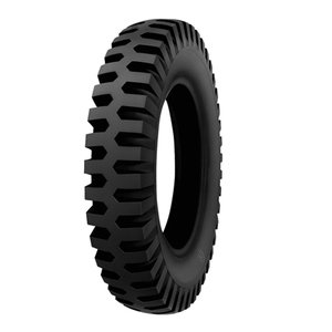
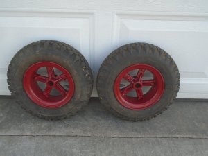
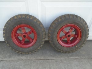
These are the tires that will be going on these rims.

DSC03675.JPG

DSC03676.JPG
 
Change of plans ....

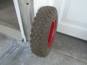
First off .. I have decided against using the lug style tractor tires that I had shown earlier on this.
This is going to be a cart for running around the tractor shows so I'm going to use this style of tire instead.

deestone-6.00x16 tire.jpg


Ever since I have started thinking about building this cart, there has been one thing that has bothered me and that is the overall length of it.Any of the 2-wheel garden tractors that I have seen with a trailer attached have all been rather long.
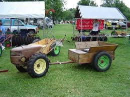
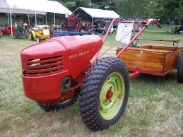
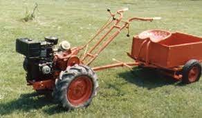
Here are some photos of some with trailers.

dss1.jpg dss3.jpg dss2.jpg


Granted .. these all have the control arms on them which makes the trailer have to be back farther from the tractor.
Mine does not have the control arms on it so the trailer tongue wouldn't have to be as long as these but it would still have to be long enough so the tires wouldn't hit the trailer when I turn.

Trying to figure out how to keep the thing as short as possible has been in the back of my mind all along as I work on it.
There was a tractor swap meet this morning at Brookville,Indiana, which is about a good hour and a half from me.
I had not planned on going to it because there is going to be another one next Saturday that will be only about a half hour from me.
While eating breakfast, I decided to go ahead and drive up to Brookville and I'm sure glad that I did.

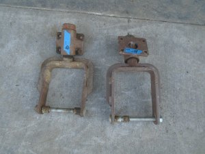
The third place I looked at had these two front swivel casters from a Grasshopper mower.
As soon as I saw them I knew that was just what I needed and they were the only caster yokes that I saw there.

DSC03678.JPG


Originally I was going to have a trailer tongue that would keep the tractor and trailer in line vertically and still let it turn and rock side to side when going over uneven ground.
I'm planning on having a two passenger seat and I'm going to mount it right at the front of the trailer.
Using these casters for the trailer wheels, I can mount the trailer solid to the tractor with just enough room between it and the back of the tractor for a foot plate between them.

I will mount these casters to a axle that will pivot in the center, like a garden tractor front axle, and this will allow the movement needed for the rear wheels to go over uneven ground.
With the trailer box now mounted solid to the tractor, the tractor will now turn like a zero turn mower with it pivoting around the inside wheel when that brake is applied.

It just so happens that way up on the top shelf of my tire storage rack, I have two 4.00x7 tires with split rims that are cast iron.
I don't have any idea of what these are from but they sure look like something that would have been available in the 30's and 40's so they will blend right in with the age of the tractor.
The tires are 14 inch diameter on the outside and the casters only have clearance for 12 inch tires so I will have to extend the forks a little.

DSC03681.JPG

DSC03682.JPG

DSC03683.JPG
 
Was I ever surprised today ..... I came home from church this morning and there were two new tires sitting on my front porch. FedEx had delivered them on Easter Sunday !
So I spent the afternoon working out in my garage.

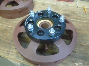
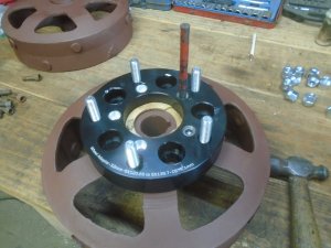
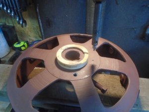
The hole in the center of the wheel adapters is larger than the center boss that I had turned down on the tractor hubs so I I turned down a wood sleeve to fit between them.

DSC03689.JPG


I knew when I bought the wheel adapters that I would not be able to use the existing bolt holes to fasten them to the tractor hub.
You can see here that about a third of the hole is out past the edge of the casting.

DSC03690.JPG


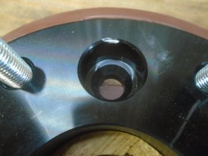
I drilled and counter board five holes for 3/8 Allen head cap screws in the wheel adapters.

DSC03691.JPG


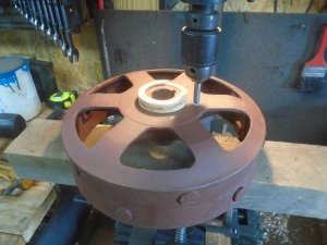
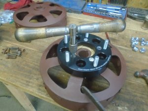
The adapter is set back on the hub and one hole is center punched.
That one hole is then drilled out to the size and threaded for a 3/8-16 thread.

DSC03693.JPG


The adapter is located on the hub with that one screw and the other four holes are center punched.

DSC03694.JPG


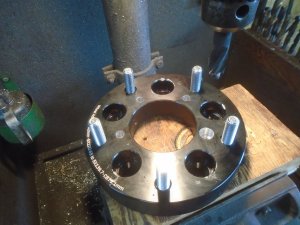
Those four holes are then drilled out to size but that are not threaded on the drill press.

DSC03695.JPG


The adapter is mounted back on the hub and the four holes are threaded by hand thru the holes in the adapter.

DSC03696.JPG


The wood sleeve is removed to be used on the other hub.
The adapter is mounted to the hub with Lock-tight put on the threads of the 3/8 cap screws.
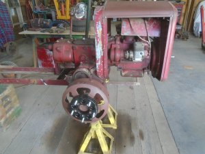
Here is how it looks on the tractor axle.

DSC03697.JPG


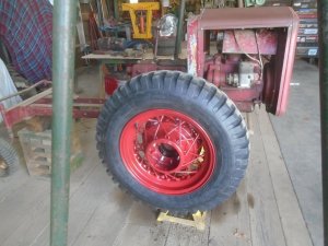
And with the wheel and tire on.

DSC03699.JPG


The tractor will have a little wider stance with these wheels on it.
You can see that the tire is sitting about 2-1/2 inches farther out than the original wheel hub.

DSC03700.JPG
 
With the tires mounted, I can now start on making the frame.
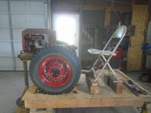
To do that, I need to have the tractor sitting on it's tires on a level surface.
As I have mention before .. at 74 years old, kneeling down and bending over while working on something like this on the garage floor cramps up my lower back.
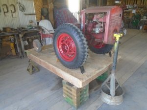
So to alleviate that condition, I take that platform that I use to get things up and out of the loft and set it up on stands.
This gives me a level surface to work off of that is raised up off the floor and much easier to work with.

DSC03701.JPG


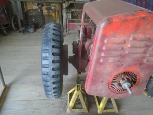
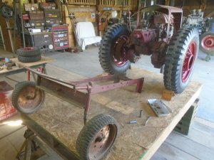
Before I remove the frame from the back of this tractor, I use a tall jack stand to support the front of it.
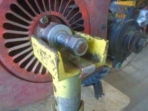
I bent up a piece of strap metal that bolts to the front of the crankshaft and wraps around the edge of the jack stand so the front of the tractor can't accidentally slip off it.

DSC03702.JPG


With the front of the tractor supported in a level position by the jack stand, I can then remove the frame from the back of the tractor.

DSC03703.JPG


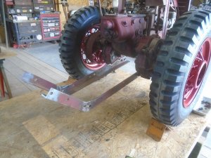
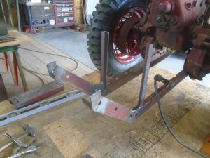
I'm using the side rails of this frame to make the new frame rails and they are mounted to the tractor about 6 inches lower then the original frame was.
The new frame is lowered in preparation of making the foot board in front of the seat.

DSC03704.JPG


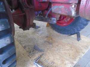
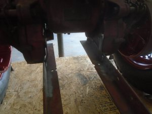
The two new frame rails are bolted to holes that are already drilled and threaded in the lower front of the axle housings.

DSC03705.JPG


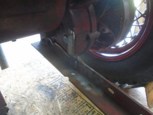
This vertical strap is welded to the inside of the frame rail and is bolted to one of the threaded holes where the original frame was fastened.
This shows how much lower the new frame is from the old frame.

DSC03706.JPG


There is a matching vertical strap on the other side also.
These two straps secure the back of the axle housings so the two wheel tractor is now securely mounted to the frame rails with three bolts on each side.

I can't go any farther with the building the frame until the rear axle with the caster wheels is built so I'll start working on that tomorrow.

DSC03707.JPG
 
Besides hoping I live to see 74, I hope if I do that I feel like doing projects. By that time I certainly don't plan to still be doing repairs for others, as I'd prefer to just be doing things for myself. I already have quite a few Bush Hog restores I'd like to do one day. Keep on keeping on Ray! We enjoy your projects!
 
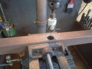
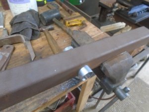
Drilling a hole thru a piece of 2 inch square tube for the center pivot for the rear axle.

DSC03728.JPG


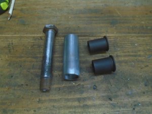
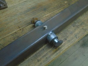
This is the steel sleeve and bushings that will allow the axle to pivot and it will pivot on the 7/8 diameter bolt.

DSC03729.JPG


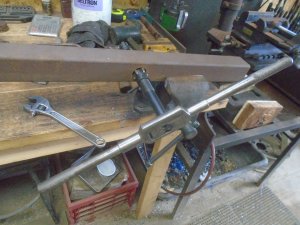
The drilled hole in the axle is a little under size so I used an adjustable hand reamer to bring it out to the correct size.

DSC03730.JPG


Now the steel sleeve fits perfectly.

DSC03731.JPG


The sleeve is welded in three places on each side of the axle.
The reason I put the sleeve right up tight to one edge instead of in the center is so I could drill thru both the wall of the axle and the sleeve to install a grease fitting.

DSC03733.JPG


I have done enough work on the two caster yokes and the wheels to figure out that I need to get some parts to complete them.

The biggest thing that I liked when I was living up in Traverse City, Michigan, was that there was a steel supply and several industrial supply stores including a Granger supply.
So whenever I needed anything, I could just drive into town and someone would most likely have what I needed in stock.
Madison, Indiana, where I live now, is a beautiful little town but it doesn't have anything more then a Walmart, a Lowe's and a TSC.

I need some 2 inch wide by 3/8 inch thick flat steel to extend the arms on the caster yokes and I need some 3/4 ID x 1 inch OD needle bearings for the wheels and two 3/4 x 6 inch hardened shoulder bolts for the axles for those wheels.
Obviously, no place in Madison is going to have any of those items so I have to order them on line.
I am far enough along though so I have a good idea of just how high off the work table the rear axle will need to be so I can go ahead and start working on the rear frame while I'm waiting for parts to get here.

The first thing is to figure out where I want the seat to go.

DSC03735.JPG


With that figured out, I weld in the two vertical pieces of angle iron for the supports for the front of the seat frame.
I also added a little bit to the ends of the two frame rails that are angled up.

DSC03736.JPG


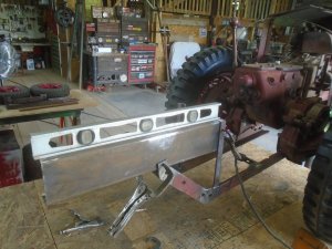
I'm using a piece of 2 inch by 5 inch steel channel for the main frame rail and it is clamped in place and leveled up, ready for welding.

DSC03737.JPG


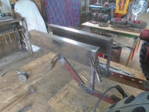
The frame rail on the other side is clamped in place.

DSC03739.JPG


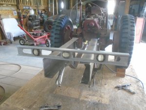
And I made sure they are square and level with each other before I weld them in place.

DSC03741.JPG
 
I'm going to use this old piece of galvanized metal to make the hood.
Here I have bent one edge up on it on my smaller brake.

View attachment 35476


Then I run it thru the roller to flatten that edge down.

View attachment 35477


Ready to bend up the opposite edge.
All four sides have been bent over to create smooth rounded edges with double metal thickness around the edges.

View attachment 35478


Back in the late 80's, I built this 3-roller sheet metal roller.

View attachment 35479


The sheet metal is clamped between the first two rollers and the back roller is moved forward or backward to control the amount of the curve.
For this piece, the back roller is drawn up tight to make the radius of the curve as small as I can get it.

View attachment 35480


The piece is put in my larger brake and a slight bend is put into the center of it.

View attachment 35481


Here is how the hood looks so far.

View attachment 35482


I'm rolling a bead along the two side edges to make them a little more ridged.

View attachment 35483


The outside of the hood is primed and mounted on the tractor.

View attachment 35484


Here is a closer look at the beaded edge.

View attachment 35485
I used a metal roller similar for fabricating culverts long ago. Adjustments could be made to rollers to attain the correct arc depending on diameter of culverts which ranged from 16" to 84".
 
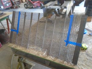
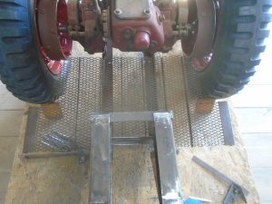
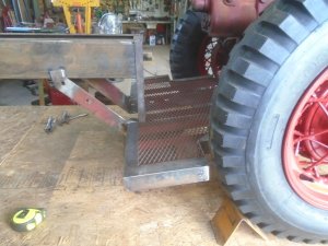
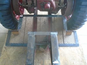
I've got an old piece of steel grating that I'm going to use for the floor.
This was a 3 by 4 foot piece and I have already cut it in half.
Here I'm getting ready to cut out two corner areas for the tires.

DSC03758.JPG


With the two corners cut out, it's time to check the fit.

DSC03759.JPG


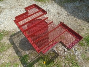
Angle iron is welded around the edges to finish it off.
It is going to be hard to paint the underside of this floor once it is installed so I primed and painted it before I fasten it to the tractor.

DSC03760.JPG


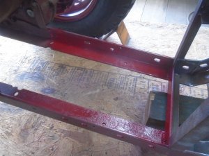
I also painted the inside of the two frame rails.

DSC03761.JPG


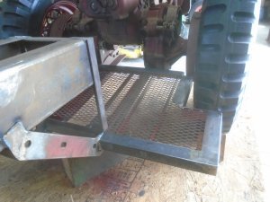
The floor section is then welded in place.

DSC03764.JPG

DSC03763.JPG


This isn't as much floor area as I had on the Ridemaster cart but it will do fine for running around the tractor shows.

DSC03762.JPG


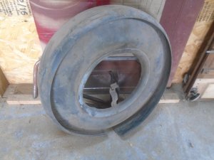
I have this old continental tire cover from back in the 50's.
I'm going to use it to make fenders and inside shields that will cover the back 1/4 of the tires so they don't rub on my shoes and pants leg.

DSC03769.JPG


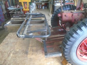
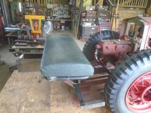
The frame for the seat is welded in place.

DSC03765.JPG


This seat frame is for the bottom section of a school bus seat.

DSC03767.JPG
 
Back
Top