Small Engine Charging Circuits - Taking The Mystery Out Of Permanent Magnet Alternators

29 Chev

Tractorologist
Senior Member
Member
In hopes of taking some of the mystery out of Permanent Magnet charging systems as to how they work and some general testing information I have decided to start a thread and share some of my knowledge on them that may help other members. I am by no means an electronics expert and if I post something that is incorrect or does not make sense please correct me or ask questions as that is how we all learn. It is my hope to keep the use of technical terms and in depth information to a minimum so that the reader does not feel overwhelmed or loose interest while reading this thread.
Please note all information in this document is presented as is – USE AT YOUR OWN RISK AND EXPENSE

Small engine Permanent Magnet Alternators which are commonly found on small engines such as may be encountered on most lawn and garden tractors since about the mid 1970’s perform the useful task of providing electricity to recharge and maintain a 12 volt battery as well as power lights, PTO clutches and other 12 volt electrical items. They usually consist of a flywheel with permanent magnets mounted inside, a stator or charge coil (or coils) which remains stationery and is bolted to the engine block and a rectifier / regulator or diode to provide rectification so that the alternating current being produced is converted to direct current and controlled so the voltage level does not rise above a preset level. It is my hope that by talking about the components and how they work together I can remove some of the mystery surrounding them while keeping the technical information and terminology needed to understand the system to a minimum.

Let us start this journey with the basic physical principle that by moving a permanent magnet placed physically close to a coil of wire a current inside the wire will be produced that can be used to generate electricity. If the two ends of the coil of wire are connected to a load such as a light bulb by using two jumper wires current will flow through the circuit and the bulb will try to light. Of course there are some other factors such as the amount of current and the voltage level in the circuit which will determine how brightly or dimly the light bulb illuminates and for how long before it burns out.

OK, I have used some words that may need explaining to some people so rather than carrying on and loosing the reader lets do that. For those readers that know what all the words mean (or think they do) – you can proceed to the next paragraph if you wish. A permanent magnet is a piece of ore or other material that exhibits a magnetic force that attracts (or repels) it to other magnetic objects – a magnet you might be familiar with is a refrigerator door magnet. A magnet can also be created by passing an electric current through a coil of wire wound around an iron object such as a nail – these are referred to as electromagnets. In a PM (Permanent Magnet) alternator a coil of wire can be one or multiple coils of wire connected together in series or parallel to form a stator or charge coil (or coils). The wire is usually copper and wrapped around but insulated from an iron laminated core frame – the laminated core helps with keeping eddy currents from forming which can create heat and aids in making sure the maximum amount of current is produced in the coil of wire as the magnet passes near it. A circuit is formed by connecting two or more conductors (wires) to a current source (in our case the coil of wire) and a load (in our case the light bulb) such that there is a circular path through which a current can flow. Current is the movement (or flow) of an electric charge – in simple terms it is the part of electricity that performs the work and is measured in amps. Current flow in an electrical circuit can be compared to the amount of water that flows through a pipe in a water system during a given amount of time. Voltage is the potential difference between two points in an electrical circuit and is measured in volts. Voltage can be compared to the amount of pressure at two different points in a water pipe as the water flows. A load can be anything that can be connected to an electrical circuit to convert electricity into light, heat, motion etc. – a light bulb, a starter motor, a heating pad in a car seat are all examples of a load. Hopefully this explains all the words that may appear to be mysterious – if not please feel free to ask and I will attempt to do a better job.
 
Now that we have the explanations out of the way let’s add a little bit of history as to why an alternator is now used to generate electricity rather than our friend the generator which did the job in the automotive world until about 1964. Back about 1964 automotive manufacturers were starting to place more demands on the electrical system by adding more accessories such as power windows, power tops (in the case of convertibles), brighter and more lights, etc. They discovered that an alternator was a much more efficient way of producing electricity in a car to power accessories and recharge the battery after the engine was started. Up until this time period Direct Current generators were being used to provide electricity and they had several draw backs compared with an alternator. Generators were much heavier, bulkier units and needed to be rotated at high RPM’s (8000 to 12000 rpm) to generate enough current output that was needed to power ignition systems, headlights, heater motors, wiper motors, etc. and recharge the battery. While the generators did the job the load being placed on a cars electrical system as other accessories were scheduled to be added required manufacturers to come up with a way to easily produce more power. Another draw back of a generator was that they required that both current output and voltage levels to be limited so that no damage was done to the generator or electrical components in the vehicle being powered – direct current generators by their design are not self limiting and can overheat if too much current is being produced. Alternators could produce much higher amounts of current at much lower RPM’s and the amount of current being produced was self limited by design so that only the level of voltage needed to be limited to about 14.4 volts so that no damage was done to any of the vehicles electrical components.

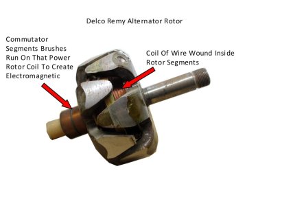
Small engine manufacturers quickly followed suit and for the most part replaced generator and starter generator set ups on small engines with separate starter motors for starting the engine and a form of an alternator to provide current output to power accessories and recharge the battery. Rather than use a separate externally mounted alternator most small engine manufacturers chose to use a PM (Permanent Magnet) alternator contained under the flywheel to provide electricity. While PM alternators operate in similar fashion to a car alternator to provide current output there are a few differences. While both alternators use a form of a stationery stator or charge coil (coils) the moving part of the alternator that provides the magnetic force is different. In most automotive alternators the moving portion is called a rotor and consists of a coil of wire mounted inside claw like poles – it rotates on a shaft and is powered with a small electric current by two light duty brushes connected to a commutator. The circuit supplying current to the rotor coil can be switched on and off rapidly (many times per second) to control the output of the alternator by increasing or decreasing the electromagnetic force created by the rotor as it passes by the stator windings. This means that at low RPM’s the rotor can be powered on for longer time intervals to increase the electromagnetic force if necessary to maintain a constant voltage level in the charging system. Here is a picture of a rotor from a Delco Remy alternator so that you can see the commutator segments and the coil of wire inside the rotor segments. Two brushes feed a small amount of current to the rotor to change the rotor into an electromagnetic of varying strength as the current is turned on and off by the voltage regulator.

5 Delco Remy Alternator Rotor.jpg
 
Most PM alternators use permanent magnets aligned and mounted inside the flywheel to create the magnetic force that passes over the stator (or charge coils) to produce electricity. Since the magnets always remain a fixed distance away from the stator (or charge coils) the amount of current produced varies as engine speed increases or decreases and the magnetic force produced by the magnets cannot be used to control the voltage level in the system. This type of system produces more current as the engine speed increases and has the lowest amount of current output at idle. In small engine applications this is usually not a concern as at idle the PM alternator is still producing some current which is an improvement over an older generator system where the generator would usually not produce useful output below about 1300 rpm's.

Both alternators require some form of rectification to convert the alternating current being produced into direct current – this is usually accomplished by one or more diodes or a rectifier bridge. I have used a couple more unfamiliar words that may require an explanation. A rectifier bridge is simply a number of diodes configured in such a way that one or three phases of alternating current can be converted into direct current. A diode is an electrical component that only allows the flow of current to happen in one direction. It can be thought of as a one way valve placed between a water tap and a garden hose so that water can flow from the tap into the hose but will not allow water to flow from the hose back into the tap. Once the current has been converted from alternating current to direct current then it is only necessary to limit the voltage level of the current being produced so it does not damage electrical components. In most automotive alternators this is done by a voltage regulator switching the current being supplied to the rotor coil winding on and off rapidly so that the voltage level at the alternator output terminal remains relatively constant and never goes above a preset voltage of about 14.4 volts. It should be noted that newer vehicles have “smart” charging systems that may allow the voltage level in the charging system to approach 15 volts at certain times to prolong battery life. A PM alternator cannot be regulated in the same manner to limit the voltage level so the voltage regulator for most PM alternator systems shunts current to ground by turning an electronic switch connected to ground on or off quickly as required so that the voltage level flowing from the regulator to the battery and other electronic components remains around 14.4 volts. The electronic switch most often used in older shunt regulators was a silicon controlled rectifier (SCR) but most newer shunt regulators use a high speed high current transistor (MOSFET) to do the shunting job as they do it quicker and more efficiently resulting in less heat being created during the shunting process.

This covers the basics of how a PM alternator usually works on a small engine application and it is my hope I have not oversimplified or added too much technical information to make this learning journey enjoyable. Next we shall venture deeper into stators and charge coils - if interested stay tuned.
 
Stators and Charge Coils

Most small engine PM alternators consist of three variations – one wire, two wires or three wires exiting from behind the flywheel area and being connected to a rectifier regulator or diode . It should also be noted that there may be one or more other wires that exit from under the flywheel as well and they are usually for the ignition system. Sometimes ignition primary and secondary charge coils that control and power ignition coils are configured into a charging stator by a manufacturer. Also sometimes lighting coils to power lights may be incorporated into a stator on engines not designed to be used with a battery. While these are equally important it is not my intention to discuss them as this article deals strictly with PM alternator charging systems. I strongly recommend that anyone who is attempting to service and repair a small engine charging system obtain the proper service data and a complete wiring diagram to verify the type of charging system they are dealing with and use the service data recommended testing procedures to determine a problem. Having said that sometimes service information is not readily available and a repair person is left to fend for themselves so to speak -this is one of the reasons for this article. Please note that all information is presented as is and the reader assumes all responsibility when applying it to a specific application. Some testing procedures require an engine to be running so always work safely and use PPE to avoid injury – remember one second of forgetfulness or stupidity can result in a lifetime of suffering and pain!

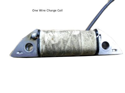
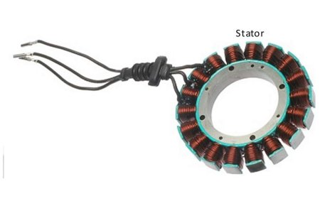
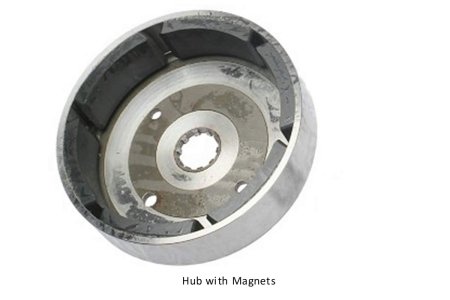
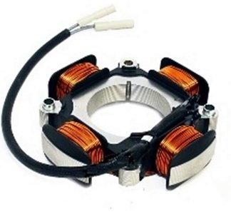
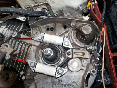
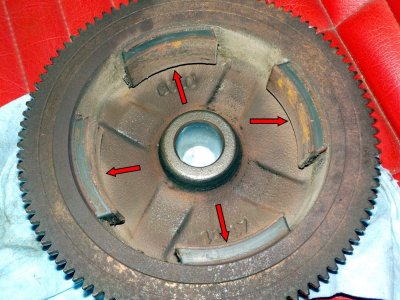
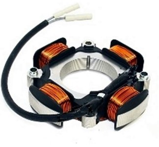
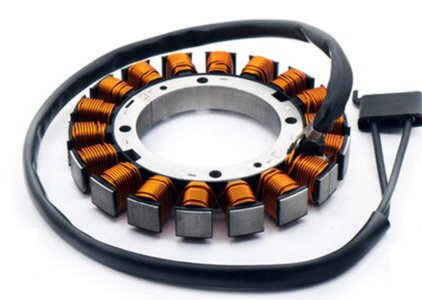
Here are some examples of flywheels, stators and charge coils that may be found on small engines.
10 3 Amp Charge Coil.jpg15 Stator.jpg16 Hub With Magnets.jpg12A 18 Amp Honda Stator.jpg
13 10 Amp Charge Coils.jpg14 Flywheel Magnets.jpg
 
As can be seen stators and charge coils may look different and have different numbers of poles but they all work using the same basic principle to create electricity – a permanent magnet being passed near a coil of wire. Flywheels may have varying numbers of magnets and the magnets may be glued directly to the flywheel or the magnets may be mounted on a removable hub that mounts inside the flywheel. Your engine will probably be similar but not necessarily the same as these pictures.
 
One Wire PM Alternators

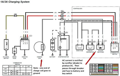
One wire PM alternators usually only provide a maximum of about 3 amps of current and are usually designed to provide a constant trickle charge to maintain a battery. They have very light gauge wire windings on a single charge coil and one end of the coil is connected to the frame of the charge coil. Since the charge coil is bolted to the engine this completes a connection from one end of the coil to form a circuit. It is only necessary to connect the single wire coming from the other end of the coil to some form of a rectifier to change the Alternating Current to Direct Current and then to a load such as the positive terminal of the battery to form a completed circuit. These alternators are usually connected by the wire to a single diode that acts as a half wave rectifier to change the alternating current to direct current by blocking any negative current flow. The diode may be located as a stand alone component or it may be hidden in the wiring harness covered by tape or heat shrink. Since only one diode is used the resulting rectification is considered a half wave type as the negative half of the Alternating Current cycle is blocked by the diode and does not contribute to the current output. Here is a wiring diagram for a Honda GX390 engine equipped with a one wire PM Alternator.
Wiring DIagram Honda GX390 WIth 1 or 3 Amp System And Electric Start With Notes.jpg
 
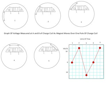
Let us examine what happens as a magnet mounted on the flywheel passes over the charge coil while trying to not get too technical. Each magnet mounted on the flywheel has a North and South Pole and as the flywheel rotates from the engine being started each pole of the magnet passes over the charge coil.
42 Charge Coil Voltage As Magnet Passes Over One Pole.jpg
Please be aware that I have marked the magnet arbitrarily as to which end is the North Pole and which end is the South Pole to keep things simple. Some readers may say that the flywheel positions I have drawn is showing the engine running backwards which may well be depending on how you view the flywheel and charge coil as being seen from the crankcase side or facing the flywheel. While I may have things a bit confusing to some the reality is that it does not matter as regardless of the direction of the rotation of the engine and the location of the North and South Pole on the magnet alternating current will be produced when the flywheel is turning over the stationery coil as shown in the graph depending on where the magnet is in relation to a pole on the charge coil. When the North Pole begins to pass over one end of the charge coil the current will begin to flow one way and the amount of current will increase until the center of the magnet passes past the charge coil. Then the current will begin to drop as it is forced to change direction as the South Pole approaches. Eventually the South Pole will begin to pass over the charge coil and the amount of current, now flowing in the opposite direction, will increase. The South Pole will eventually reach the end of the charge coil and current level will again drop until the next magnet passes as the flywheel rotates. Please note that the voltage levels I have picked on the graph are arbitrary and in real time the graph would appear more like a sine wave since an idling engine would be running at about 1000 rpm making the frequency at which each cycle happens would be about 133 times per second. This cycle continues as long as the flywheel is rotating and as a result positive and negative pulses of current will flow from the charge coil to the diode since they are connected in a circuit. Since the diode acts as a one way valve it will permit the positive pulses of current to flow through it to charge the battery but the negative pulses of current will be blocked by the diode. Given that the amount of current this type of PM alternator produces is limited to about 3 amps most manufacturers do not use a voltage regulator and allow the unregulated current to flow directly through a fuse or circuit breaker to the battery. The design of these small PM alternators is such that the DC voltage will probably never exceed 14 volts. This action is very similar to what one might see if a battery was constantly connected to a small battery charger or maintainer.
 
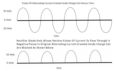
One other thing that should be mentioned is that because only one diode is being used to rectify the Alternating Current to Direct Current slightly less than half the current that is produced by the charge coil is actually passed on as Direct Current. This is because the negative voltage cycle of each current pulse is being blocked by the diode as I will attempt to illustrate. Please keep in mind that, unlike Direct Current, Alternating Current is constantly changing direction and at certain brief time intervals the voltage level of the current will be zero. There will also be times where the voltage level is rising or falling near the start or end of each magnet passing over a charge coil pole – this will result in a voltage level that is not high enough to be useable. Most rectifier diodes require a current with a voltage level of approximately 0.7 volts before they will allow current to flow through them.

Here is a picture to illustrate what happens when only one diode is used as a rectifier.
43 Single Diode Rectification Waveform.jpg
It is always good to remind ourselves that a bad battery or parasitic drain can also make it appear that the charging system is not working properly. It is best to verify that you are working with a good fully charged battery before automatically assuming that the charging system is at fault if an engine will not crank over and the battery appears to be discharged.
 
Testing of One Wire PM Alternators

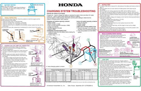
Consult the manufacturer’s specifications and service manual for the correct test procedures if available. The attached troubleshooting chart published for troubleshooting the Honda GX390 engine illustrates information available from a manufacturer that can be used to check a charging system problem.
44 GX390 Charging Troubleshooting Information.jpg
If this service information is not available there are a few tests that can be performed on one wire PM alternators to verify if they are working. It is assumed that the battery is not staying charged and that upon start up the battery voltage when measured at the battery terminals using a DC voltmeter is not rising as it would if the charging system is working properly. On a single wire PM alternator set up one end of the charge coil wire is probably connected to the charge coil frame to create a circuit path for that end of the charge coil to ground. The other end of the charge coil will be connected to a wire which exits from under the flywheel area. Disconnect the wire that comes from the charge coil where it is plugged into the wiring harness – there is usually a connector very near the engine to make it easy to remove the engine if necessary. Verify that you are disconnecting the correct wire as there may be other wires that connect to the ignition circuit. Once the wire is disconnected you can use a multimeter set to measure AC (alternating current) voltage to see if the charge coil is creating any AC voltage. Connect one lead of the meter to the wire that comes from the charge coil and the other lead of the meter to then engine block (ground). Start the engine and observe the meter reading to see if any readable voltage is being produced – at idle you should probably see a reading of around 20 volts. Increase the engine speed and observe the meter reading – as the engine speed increases the voltage reading should rise and at wide open throttle you should see a reading of around 24 to 28 volts. If readings similar to these are observed the PM alternator part of the system is probably working and there may be a wiring problem, a blown fuse or open circuit breaker or the rectifier diode may be open or shorted. The rectifier diode may be a visible component or it may be concealed in the wiring harness under a layer of tape or covered by heat shrink. Most modern multi-meters are capable of testing a diode to verify it is ok. If the diode test ok then odds are the charging system is functioning and any electrical problem that made you think the charging system was at fault may have be checked in other ways.

If there was no or a very low voltage reading observed with the AC voltmeter first verify that you have the multimeter set to measure AC volts and not DC volts – this is an easy mistake to make and I have done it myself. Once that is verified it may be assumed that the charge coil, a connection or wire going to it or the flywheel magnets are bad. You can do a test on the charge coil using one lead of an ohmmeter connected to the single wire and the other lead of the ohmmeter connected to ground. A low ohm reading should be observed on the meter – this may be around 1 ohm or less and some inexpensive multi-meters may not be able to read such a low resistance reading accurately and it might appear that the charge coil winding is shorted to ground. The windings in the charge coil may be shorted to ground and it may be necessary to remove the charge coil from the engine to determine this. If a high or infinite resistance reading is observed the coil winding may be open or the one end may not be connected to the charge coil frame – some are just connected with a drop of solder. It may be necessary to remove the flywheel and unbolt the charge coil so it can be inspected for burn or heat marks and to verify that the frame end of the wire is still intact. With the flywheel removed it will also be easy to verify the magnets are still intact and that they have not lost their magnetic field by placing a flat steel screwdriver or a hacksaw blade near them and observing if an attraction is felt.

This concludes the theory and testing information I can offer on a one wire PM alternator and soon we shall turn our attention to a two wire PM alternator.
 
Two wire PM Alternators

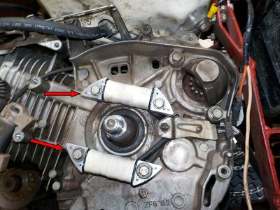
Two wire PM alternators usually are capable of providing an output current of between 10 and 20 amps and are designed to charge the battery and also provide extra output to power accessories such as lights or electric PTO clutches. There may be two charge coils connected in parallel to two output wires to create a PM alternator such as what a Honda GX390 equipped with a 10 amp charge system uses. On their 18 amp charging system for a Honda GX390 engines they use a four pole stator assembly that has a coil of wire wound around each pole and connected in series which terminate in two wires. Here is a picture of the two charge coils used on the 10 amp system and also the four pole stator they use on their 18 amp system.
13 10 Amp Charge Coils.jpg12A 18 Amp Honda Stator.jpg
Other manufacturers usually use a stator with multiple smaller poles (the number of poles may be as high as 18) where there are small coils of wire wound around each pole with each coil connected to the next in series and the coils terminate in two wires.

Here is an example of what one of them might look like – this is what you might find behind a Kohler K662 flywheel
12B Kohler Stator.jpg
The magnet wire used to form the coils of wire in these higher output PM alternators is usually around 16 gauge. In each case both wires connected to the charge coils are isolated from any ground point so the alternating current produced is isolated from the direct current electrical system of the tractor. The two wires of these PM alternators are usually connected to some type of a combination rectifier / regulator unit that converts the alternating current to direct current using some form of rectifier circuit and also limits the voltage level so it does not rise above about 14.4 volts with some form of a voltage regulation circuit. The number of magnets inside the flywheel may vary but as they pass by the poles once the flywheel is rotated alternating current will be produced.
 
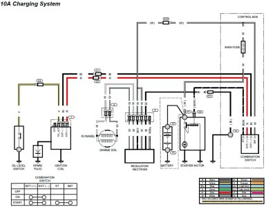
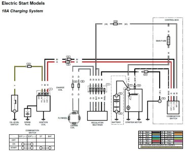
Here are two wiring diagrams for a Honda GX390 engine equipped with two wire PM Alternators – a 10 amp and 18 amp charging system. One thing that I will mention is the 10 amp system only shows two magnets mounted in the flywheel but in actual reality the engine I have has four magnets mounted inside the flywheel. You may also notice that the rectifier / regulator plug in each drawing shows 6 terminals of which one is not connected. The terminals are configured as such in this system. Two terminals are connected to the two wires from the PM alternator that produces alternating current. One terminal is connected to the chassis ground to complete the direct current part of the circuit once the current has been rectified to produce direct current. Two terminals are connected together and are connected through the ignition switch and a fuse to the positive terminal of the battery. One of the two terminals allows current to flow to the battery and the other terminal is a type of sense wire to determine the voltage level at the battery. The last terminal is not connected to anything in the diagram – its purpose is so a charge indicator lamp can be connected to it and the other end of the lamp circuit can be connected through the ignition switch to the battery positive terminal if desired. When a light is connected in this fashion the light will illuminate with the key on and the engine not running and once the PM alternator starts producing the light will go out. Other rectifier / regulator units may have a different number of terminals – most Kohler units only have three terminals. On these two of the terminals are connected to the two wires from the PM alternator and the third terminal is the positive output of direct current that gets connected the battery – usually through a fuse and ignition switch. The case of the rectifier regulator serves to provide the ground side of the direct current and must be connected to a good chassis or engine ground for the rectifier / regulator to function properly.
Wiring DIagram Honda GX390 WIth 10 Amp System And Electric Start.jpgWiring DIagram Honda GX390 WIth 18 Amp System And Electric Start.jpg
 
As stated these higher output PM alternators require a voltage regulator to limit the amount of voltage to protect the battery and other electrical components. Most manufacturers choose to combine the rectification of the alternating current to direct current and the voltage regulation inside a single unit that most simply label a voltage regulator on a wiring diagram. I will still refer to it as a rectifier / regulator since it does both tasks in combination. Since the PM alternators output cannot be controlled by changing the strength of the magnet as it passes by each coil most manufacturers shunt the output of the charge coil wires to a common ground point for a very brief period of time many times per second so that the alternating currents voltage level drops to an acceptable level as monitored in the direct current portion of the charging system at the battery terminals. This is done using an electrical component such as a SCR (silicon controlled rectifier) or a MOSFET (metal-oxide-semiconductor field-effect transistor). Since either of the two wires from the PM alternator may be positive or negative depending on whether the pulse being produced is positive or negative at any given point in time one of these switches must be connected to each output wire. I will not go into much depth about these two components other than to say that they acts as an electronically controlled normally open switch with one end connected to one of the output wires from the PM alternator and the other end connected to a ground point. As long as the voltage level at the battery remains at or below about 14.4 volts these switches will remain open - if the voltage level at the battery rises above that the switches will temporarily close. This in effect shorts the PM alternators current output at the two wires together and the switches are tied to a common ground point causing the output to fall momentarily until the voltage level at the battery drops to an acceptable level. Once that occurs the switches will return to their normally open state and output current from the PM alternator will resume – remember this is occurring many times per second. I believe the reason they are tied to the common ground point is so that there will not be a high level of voltage present when the switch reopens – a high voltage level could create a momentary spike when current was allowed to flow into the rectifier bridge and damage one or more diodes. As you can imagine this constant shunting of the alternating current to a ground point creates a lot of heat in the electronic switches as well as other components and that is one of the reasons why the rectifier/regulator bodies are usually fairly large and made of aluminum so the heat can be dissipated quickly away from the electrical components inside.
 
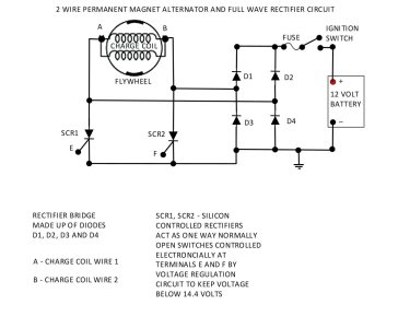
Since using a single diode is not a very efficient way of turning the alternating current to direct current (as we saw in the single wire system about half the current being produced was not used) most rectifiers used in the two wire systems consist of four diodes arranged in what is commonly called a bridge rectifier. Another new word that may puzzle some readers so let us talk about a bridge rectifier for a moment. A diode, as stated earlier, acts as a one way valve and will only allow current to flow in one direction. Using one diode will only allow the positive portion of an alternating current to flow and will block current flow in the opposite direction as we saw in the one wire PM alternator system. However four diodes can be configured to form a bridge so to speak so that both the positive and negative portions of the alternating current cycle can flow through the bridge that the diodes form to become direct current. Below is a drawing that shows the four diodes configured in such a manner and also shows how the electronically controlled normally open switches would look in a circuit.
51 Single Phase Rectifier.jpg
 
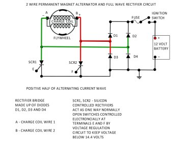
I have chosen to show the 10 amp charge coil PM alternator in the drawing but any two wire PM alternator will produce alternating current at points A and B in the circuit. Let us examine what happens when the alternating current is positive at point B and negative at point A.
52 Single Phase Rectifier Positive Half OF Current.jpg
Diodes D1, D2, D3 and D4 make up the Rectifier Bridge. Since the current at this point in time is positive at point B and negative at point A current will flow from point B to the junction of diodes D1 and D3 in the rectifier bridge. Due to the way the diodes are configured diode D1 will allow the current to pass though it to the positive battery terminal if the ignition switch is closed. Diode D3 will block any current flow to ground. Once current has flowed through the battery to the negative battery terminal the current will flow to the junction of diodes D3 and D4 where diode D4 will allow the current to flow to point A to complete the circuit.
 
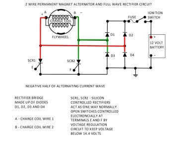
Now let’s examine what happens when the alternating current is positive at point A and negative at point B.
53 Single Phase Rectifier Negative Half OF Current.jpg
The current will flow from point A to the junction of diodes D2 and D4 in the rectifier bridge. Due to the way the diodes are configured diode D2 will allow the current to pass though it to the positive battery terminal if the ignition switch is closed. Diode D4 will block any current flow to ground. Once current has flowed through the battery to the negative battery terminal the current will flow to the junction of diodes D3 and D4 where diode D3 will allow the current to flow to point A to complete the circuit.
 
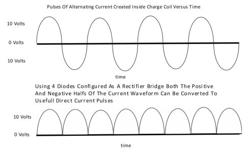
This is a picture that shows what the alternating current pulses that are being generated by the two wire PM alternator look like by using a full wave (4 diode) rectifier – unlike what we saw using a single diode with the one wire PM alternator the negative half of the pulse cycle is not blocked but is now converted into a second useful pulse of direct current during each cycle.
55 Full Wave Rectification Using Four Diodes Waveform.jpg
 
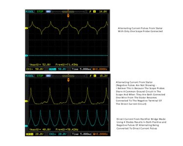
For those interested here is a picture of the waveform that is produced on an oscilloscope by the 10 amp PM alternator on my Honda GX390 using a full wave rectifier. Another unfamiliar word - an oscilloscope is simply a very fast voltmeter that is capable of graphing the voltage level in a circuit over time (at a rate that cannot be detected by the human eye in real time) and displaying it on a screen as a bar graph that is usually referred to as a waveform. In the first waveform I have the second scope probe disconnected from the circuit so that both positive and negative pulses of alternating current being produced during each cycle can be seen. As you can see that while they are not a true sine wave type of a waveform as I showed in my drawings there are positive and negative pulses of current with positive and negative voltage peaks and at brief moments in time the waveform is almost horizontal at the same level as the start of the waveform indicating a voltage level very close to zero and at these times very little current is flowing from the stator wires. The time base is set such that the space between each grid line of the graph represents 5 ms (one thousand of a second). In the second waveform image you can see that both the negative and positive current pulses are being converted to positive direct current pulses as shown by the blue waveform. The negative pulses in the yellow waveform have disappeared – I believe this is because with both scope probes connected one of the PM alternator wires is connected to the ground of the direct current side of the circuit since both probes share a common ground connection inside the scope.
56 Waveform Of 2 Wire Output And Full Wave Rectifier.jpg
As can be seen the current pulses in the direct current side of the rectifier are all positive but there are brief periods in time where the voltage level is at or very near zero as the PM alternator output pulses switch polarity and the current direction reverses. These short durations of zero voltage don't hurt anything and will not show up when voltage in either the alternating current or the direct current circuits is measured using a regular voltmeter but I wanted to point them out since this is one of the major differences between two wire and most three wire PM alternators as we will discover.
 
Testing Of Two Wire PM Alternators

Consult the manufacturer’s specifications and service manual for the correct test procedures if available. The troubleshooting chart I posted in the Testing One Wire PM Alternators post can be referred to as an example of service information as it shows what Honda published for troubleshooting the Honda GX390 engine with a 10 or 18 amp charging circuit.

If this service information is not available there are a few tests that can be performed on two wire PM alternators to verify if they are working. It is assumed that the battery is not staying charged and that upon start up the battery voltage when measured at the battery terminals using a DC voltmeter is not rising as it would if the charging system is working properly. On a two wire PM alternator set up both output wires are probably insulated from any ground point as part of the circuit design. Disconnect the two wires that come from the charge coil where it is plugged into the wiring harness – there is usually a connector very near the engine to make it easy to remove the engine if necessary. Verify that you are disconnecting the correct wires as there may be other wires that connect to the ignition circuit. Once the wires are disconnected you can use a multimeter set to measure AC (alternating current) voltage to see if the charge coil is creating any AC voltage. Connect one lead of the meter to one of the wires that comes from the charge coils (or stator) and the other lead of the meter to the other wire from the charge coils (or stator). Start the engine and observe the meter reading to see if any readable voltage is being produced – at idle you should probably see a reading of around 25 volts. Increase the engine speed and observe the meter reading – as the engine speed increases the voltage reading should rise and at wide open throttle you should see a reading of around 28 to 32 volts. If readings similar to these are observed the PM alternator part of the system is probably working and there may be a wiring problem, a blown fuse or a bad rectifier / regulator. Check the connections at all the terminals where the wires connect to the rectifier / regulator as well as the wires that connect it to the PM alternator output wires to verify they are not shorted or open using standard testing procedures. Check to make sure that the wire that connects to the ground terminal on the rectifier / regulator (if so equipped) has good continuity with the negative terminal of the battery. If the rectifier / regulator is a three terminal style make sure the body of the unit has a good ground. Running a temporary jumper wire from the body of the regulator / rectifier to the negative terminal of the battery can be done to verify there is not a bad connection through the chassis. Also check the fuse in the wiring as having an open circuit between the body of a three terminal rectifier / regulator and the ground point can sometimes result in the fuse blowing from my experience. If the PM alternator is outputting an AC voltage of 28 to 32 volts and all other connections and switches have been verified as having good conductivity then odds are the rectifier / regulator has failed. There is no way of accurately testing most rectifier / regulators that I know of and from what I have read. There are tests suggested by manufacturers to determine the integrity of the rectifier diodes but these will usually prove inconclusive and most will eventually tell you to replace the rectifier / regulator with a known good working unit to see if it fixes the problem.

If there was no or a very low voltage reading observed with the AC voltmeter first verify that you have the multimeter set to measure AC volts and not DC volts – this is an easy mistake to make and I have done it myself. Once that is verified it may be assumed that the charge coils or stator, a connection or wires going to it or the flywheel magnets are bad. You can do a test on the charge coils or stator using one lead of an ohmmeter connected to one output wire and the other lead of the ohmmeter connected to the other output wire. A very low ohm reading should be observed on the meter – this may be around 1 ohm or less and some inexpensive multi-meters may not be able to read such a low resistance reading accurately. The windings in the charge coils or stator may also be shorted to ground and by testing each wire by connecting one wire of an ohmmeter to a ground point on the engine and the other end of the ohmmeter to one of the wires from the charge coils or stator to make sure there is no continuity to ground. If a high or infinite resistance reading is observed the coil windings should be ok but it still may be necessary to remove the charge coils or stator and visually inspect them for any signs of heat damage. It usually will be necessary to remove the flywheel and unbolt the charge coils or stator so it can be inspected on the backside for burn or heat marks.

If there are two charge coils wired in parallel as is the case on a Honda GX390 10 amp charging system one of the charge coils could be open resulting in a slightly lower voltage reading using an AC voltmeter to measure the PM alternator output or a lower level of current output and this would not show up using the ohmmeter test as the other charge coil would still have continuity when testing using an ohmmeter. In this case it would be necessary to undo one of the wires going to one of the charge coils so that each charge coil can then be tested individually. With the flywheel removed it will also be easy to verify the magnets are still intact and that they have not lost their magnetic field by placing a flat steel screwdriver or a hacksaw blade near them and observing if an attraction is felt.

This concludes the theory and testing information I can offer on a two wire PM alternator and next we shall turn our attention to a three wire PM alternator.
 
Three Wire PM Alternators – Three Phase Output

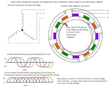
Three Wire PM alternators are not as common as two wire PM alternators in the garden tractor world but they do exist and as such I have included information on them in case they are encountered by someone. As noted this information is about a three wire three phase PM alternator and there is also a three wire two phase configuration that will be discussed later but for now we will concentrate on the three phase version. They are usually capable of producing 20 to 30 amps of current and one of the differences between them and the two wire units is that they are designed to never have zero voltage output at any point in time after the alternating pulses of current are converted to direct pulses of current. They do this by using three different charge coil circuits so that three phases of alternating current are created at approximately 120° apart from each other. This is similar to how most automotive alternators produce power by using three different stator windings that the rotor turns inside of to create 3 phases of alternating current before they are rectified and converted to direct current. So far this may sound a bit confusing to the reader so let us examine the way a stator is usually wound and connected in a three wire PM alternator system. I have drawn a 12 pole stator and a flywheel with four magnets mounted inside to keep things simple – the actual number of poles and magnets can vary.

If we look at the stator drawing below there are four purple poles labelled A, four green poles labelled B and four orange poles labelled C. The coils of wire windings on the same coloured poles are connected together in series and at one end where they terminate are connected together. At the other end where the other end of the series connected coils (A coils, B coils, C coils) we can connect three wires to form three separate circuits – A and B, B and C and A and C. These can be seen in the schematic drawing of the stator wiring. Each of these three circuits will produce alternating current when the flywheel with the magnets is rotated and the waveforms produced will look identical but they will be out of phase (time) with each other by approximately 120°. If we examine the colour coded waveforms of alternating current we can see the positive and negative pulses of current and we can also see that each will have the usual brief periods where the voltage level drops to zero but they are reaching positive and negative peaks at different points in time and the time when the zero voltage level is occurring is also different in each circuit. Since there are three separate circuits the exact period in time where each circuit reaches a zero voltage level is occurring is different depending on where the polarity of the magnet is in relation to each circuits set of poles. For example if we look at where the purple waveform has peaked positive we can see that the green waveform is at zero volts and the orange waveform is close to peaking as a negative pulse. As a result when the alternating current pulses of each circuit are converted to direct current pulses there will be no point in time where the voltage level of the direct current reaches zero since both the positive and negative pulses of alternating current produced in each of the three circuits are converted to positive pulses of current by a rectifier circuit.
62 3 Phase Stator Drawing.jpg
 
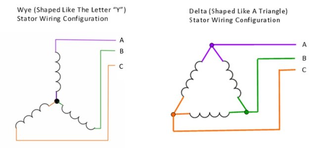
It should be noted that the stator I have shown above of a 3 wire PM alternator is shown as a Wye (looks like the letter Y) configuration where each of the three coil circuits are common and connected to each other at one end. The three circuits are all insulated from any ground point and the common connection point that is shown in the previous drawing does not connect to the stator body. The stator coils could also be connected as a Delta (shaped like a triangle) configuration where each coil is connected to the next coil and the connection points are used to connect the three wires coming from the stator to a rectifier / regulator. While both styles may differ slightly as far as the amount of current and voltage levels produced both configurations will result in three separate circuits that will produce three phases of alternating current being produced at connections A and B, B and C, and A and C. Here is a picture that shows the difference between the two configuration styles.
74 Wye Versus Delta Stator Configuration.jpg
 
Back
Top