Small Engine Charging Circuits - Taking The Mystery Out Of Permanent Magnet Alternators

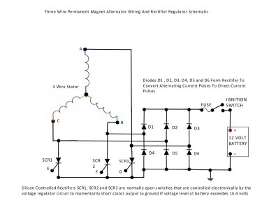
Now that we have seen how the three separate circuits form three different phases of alternating current let us examine a complete charging system circuit that uses a three wire PM alternator.

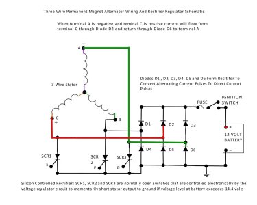
In the picture below we can see that six diodes (D1, D2, D3, D4, D5 and D6) are used to form the rectifier circuit and three Silicon Controlled Rectifiers are connected to each of the stator wires so the voltage regulator circuit can control the voltage level at the battery.
65 3 Phase PM Alternator Charging System.jpg
 
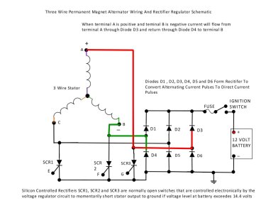
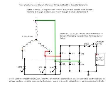
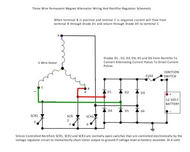
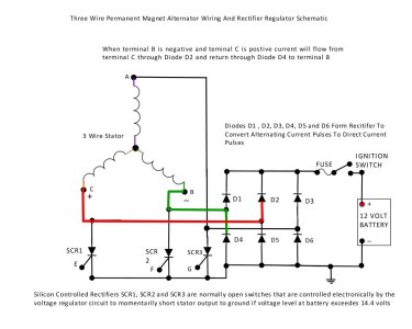
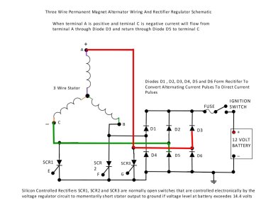
We can now examine how the positive and negative alternating current pulses from each part of the three wire stator circuit flow through the diodes in the rectifier circuit to charge and maintain the battery and other electrical accessories.
66 3 Phase PM Alternator Charging System A Positive B Negative.jpg67 3 Phase PM Alternator Charging System B Positive A Negative.jpg68 3 Phase PM Alternator Charging System B Positive C Negative.jpg69 3 Phase PM Alternator Charging System C Positive B Negative.jpg70 3 Phase PM Alternator Charging System C Positive A Negative.jpg71 3 Phase PM Alternator Charging System A Positive C Negative.jpg
 
Three Wire PM Alternators – Two Phase Output

There is another wiring configuration of a PM alternator stator that can have three wires but because of the charge coil connections there are only two phases of alternating current being produced. These systems are probably rare but I believe that some engines such as the Ducati made and Wisconsin supplied 2 cylinder Diesel that can be found on a Bolens HT20D garden tractor used this type of PM alternator. The three wires shown in the wiring diagram found in the engine repair manual for this engine show two of the wires are yellow in colour and the third wire is red in colour. In checking with some of the Ducati motorcycle forums it appears that Ducati used a similar 3 wire PM alternator on their motorcycles for a period of time and these also used two yellow and one red wire coming off of the stator.
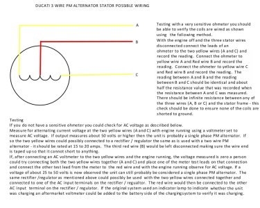
Here is a drawing of how the motorcycle stator charge coils were connected and while I cannot say for certain a guess would be that the diesel engine in a Bolens HT20D used the same stator configuration. The majority of other diesel engines that were used in Bolens tractors used a separate externally mounted belt driven automotive style alternator.


102 Ducati 3 Wire Stator Possible Wiring.jpg
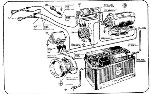
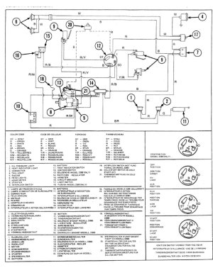
This is a wiring diagram that is shown in the engine service manual and also one from the Bolens Large Frame Service Manual.
101 Ducati 2 Cyl Diesel Wiring Diagram.jpg100 Bolens HT20D Wiring Diagram.jpg


If a three wire two phase stator was tested and working and the rectifier / regulator ended up needing replacement I will offer the following information as a suggestion only. Since the possibility of locating a new rectifier regulator for a two phase system might be a difficult task it may be possible to configure the unit so it could be connected to a rectifier / regulator such as is used on a two wire system. If the stator tested ok for output voltage at the two yellow wires with an AC voltmeter then it might be possible to connect the two yellow wires to the two stator terminals on a two wire rectifier / regulator and leave the red wire disconnected. Make sure the end of the red wire is taped up so it cannot short out on anything. If no voltage output was observed at the two yellow wires you could try connecting the two yellow wires together. Then test for AC voltage between this connection and the red wire with the engine running. If AC voltage is now observed the rectifier / regulator for a two wire system may also work by connecting the two yellow wires to one of the stator terminals and the red wire to the other stator terminal on the rectifier / regulator. In selecting a two wire rectifier / regulator I would suggest using one that is rated around 20 amps. If the tractor uses a charge indicator lamp circuit rather than a voltmeter or amp meter to show that the charging system is working a rectifier / regulator that is used on a Honda GX390 engine with an 18 amp charging system might be considered since it has a lamp circuit built into it as part of its six terminal plug configuration. The terminal is shown as unused in the Honda 18 amp wiring diagram shown earlier. These are only offered as suggestions that a reader can try at their own risk that may help in getting a three wire two phase system with a bad rectifier / regulator working again if the stator is still working.
 
Testing Of Three Wire PM Alternators

Consult the manufacturer’s specifications and service manual for the correct test procedures if available.

If this service information is not available there are a few tests that can be performed on three wire PM alternators to verify if they are working. Below is a picture that shows three possibilities as to how a three wire stator may be configured and a few tests that the reader can perform to verify if the PM alternator is producing voltage.
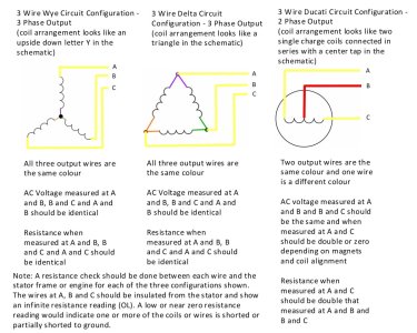
105 3 Wire Stator Configurations.jpg
Since I have never worked on a three wire stator system I cannot tell you what the resistance or voltage readings should be. In the three wire three phase configured units where all three wires are the same colour I would suggest labelling the three wires as A, B and C with a piece of masking tape so you make sure you are testing the correct wire during each test. In testing the three wire two phase stator it would only be necessary to label the two wires which are the same colour.

I would suggest that the voltage and resistance readings should be similar to what is observed in a two wire system and to make sure that all three wires have an infinite resistance when an ohm meter is used to check for conductivity between each wire and the stator frame or engine ground as each of the wire circuits should not be connected to a ground point as shown in the schematics I have drawn. The biggest thing to remember is that the voltage level at all three phases of alternating current on the three phase wiring configurations should be almost identical and that resistance checks of each of the three separate coils on a 3 phase system should also be almost identical as well. If the voltage levels of all three phases are virtually identical on a three phase unit configuration and as described earlier on a two phase unit configuration the PM alternator portion of the charging system is probably ok.

There may be a wiring problem, a blown fuse or a bad rectifier / regulator elsewhere in the charging system circuit. Check the connections at all the terminals where the wires connect to the rectifier / regulator as well as the three wires that connect it to the PM alternator output wires to verify they are not shorted or open using standard testing procedures. Check to make sure that the wire that connects to the ground terminal on the rectifier / regulator (if so equipped) has good continuity with the negative terminal of the battery. If the rectifier / regulator body of the unit acts as the ground connection in the direct current portion of the charging circuit verify it has a good ground connection. Running a temporary jumper wire from the body of the regulator / rectifier to the negative terminal of the battery can be done to verify there is not a bad ground connection through the chassis. Also check the fuse in the wiring as having an open circuit between the body of a rectifier / regulator and the ground point can sometimes result in the fuse blowing from my experience. If the three wire PM alternator is outputting an AC voltage as described earlier and all other connections and switches have been verified as having good conductivity then odds are the rectifier / regulator has failed. There is no way of accurately testing most rectifier / regulators that I know of and from what I have read. There are tests suggested by manufacturers to determine the integrity of the rectifier diodes but these will usually prove inconclusive and most will eventually tell you to replace the rectifier / regulator with a known good working unit to see if it fixes the problem.

If there was no or a very low voltage reading (under 15 volts) observed with the AC voltmeter connected as described earlier first verify that you have the multimeter set to measure AC volts and not DC volts – this is an easy mistake to make and I have done it myself. Once that is verified it may be assumed that one or more of the charge coils or stator, a connection or wires going to it or the flywheel magnets are bad. If this is the case removal and inspection of the stator is in order so it can be inspected for any burn or heat damage and to verify the exact configuration of the three wire stator to ensure the correct tests were being done.

This concludes the theory and testing information I can offer on a three wire PM alternator.

Hopefully others reading this have found it informative and now have a better understanding of PM alternator charging systems and their testing to help diagnose and repair a PM alternator charging problem.
 
For anyone wishing a pdf copy of the information I posted in this thread (for easier reading or future reference) I have attached one in this post.
 

Attachments

  • Small Engine Permanent Magnet Alternators Jan 8 2024.pdf
    1.9 MB · Views: 2
Back
Top