Free tractor

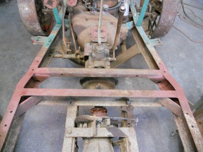
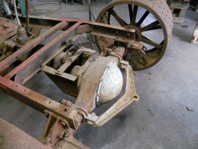
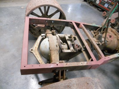
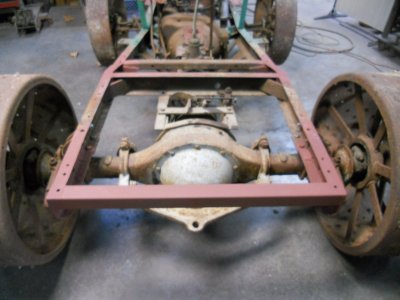
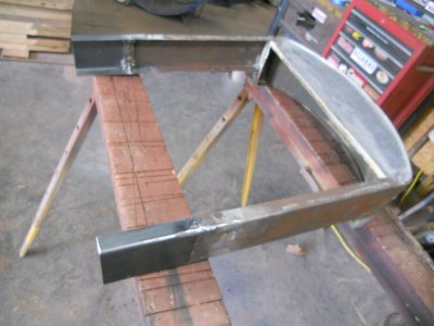
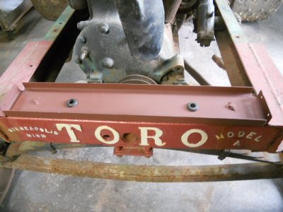
The frame splice is finished on the other side and here is how they look from the back.
DSCN2583.JPG


The back of the frame ends at the rear axle.

DSCN2584.JPG


I took about 10 inches of the two pieces of frame that I had cut out of the center and added them to the back of the frame to extend it out to about even with the back of the rear wheels.

DSCN2585.JPG

DSCN2586.JPG


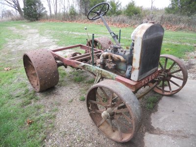
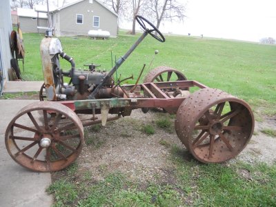
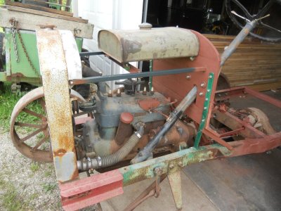
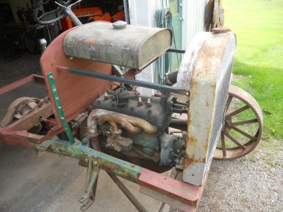
Pushed it outside to get a couple of photos.
The weather is going to start getting colder tomorrow so that will stop the work in the garage for awhile.

DSCN2587.JPG

DSCN2588.JPG
 
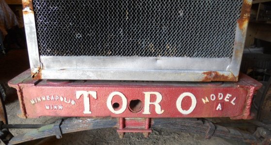
Back to work on the Toro for awhile. ............

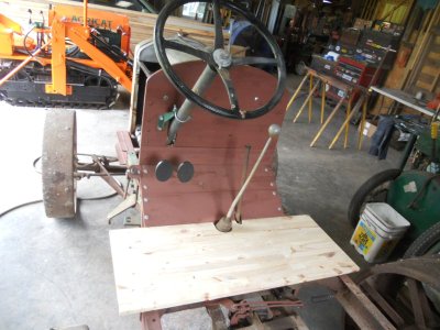
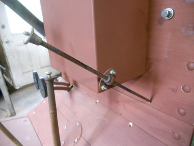
The Ford model-A steering column has both a throttle lever and a spark advance lever on it.
Originally, the model-A also had a foot pedal to operated the throttle.
Because this is a tractor, I'm going to use just the throttle lever on the steering column and not the foot pedal.

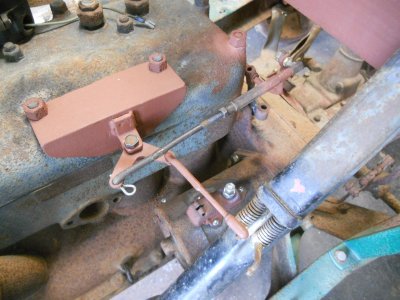
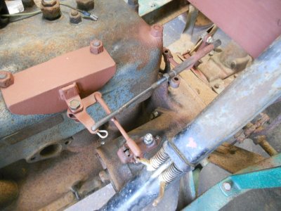
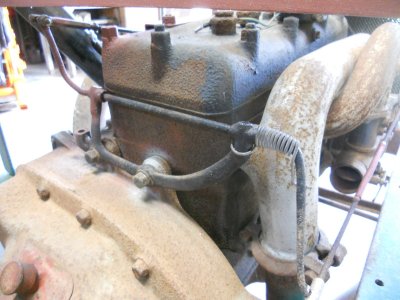
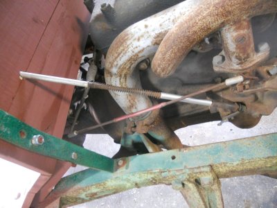
I made up a bracket that bolts onto the engine. It holds a right angle lever arm for the throttle linkage.
The linkage rod from the steering column attaches to one side of the right angle lever.
The rod that is attached to the other side of this lever runs back to a lever that is mounted on the back of the engine.

This photo is with the throttle closed.

DSCN3325.JPG


This is with the throttle full open.

DSCN3326.JPG


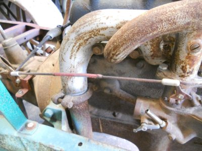
This is the original model-A throttle linkage bolted on the back of the engine.
Originally, the lever on the left was bent down and had a round metal pad on the end for the foot pedal.

I cut the round pad off and heated the lever up so I could bend it so it is now sticking up with the throttle rod attached to it.

DSCN3327.JPG


The lever on the right has the throttle rod attached to it that goes to the carburetor.

DSCN3328.JPG


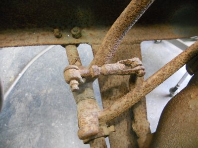
This is the rusted up clutch linkage.

DSCN3331.JPG


I used my torch to heat the parts up so I could get them separated.
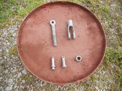
Then I sand blasted them to clean them up before I primed them.

DSCN3332.JPG


The finished parts are re-assembled.

DSCN3334.JPG
 
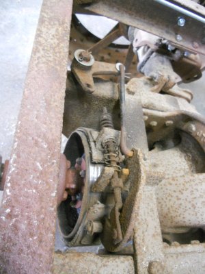
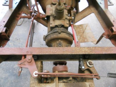
This tractor does not have any brakes on either the rear axle or the front axle.
The only brake it has is this drum brake on the front of the rear axle pinion.

DSCN3341.JPG


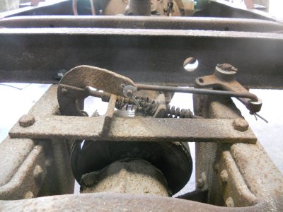
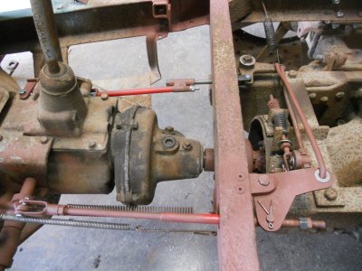
A linkage rod from the hand operated parking brake lever will come back thru the hole in the frame and attach to the left side of the right angle bracket.

DSCN3342.JPG


Pulling back on the parking brake lever would pull on the linkage rod and cause the right angle bracket to push on the ben-tover brake operating lever.

This whole system is really loose right now and in the process of moving the right angle bracket several times to engage the brake, there were a couple of times it wouldn't work unless I lifted up a little on that bent-over operating lever.

I'm guessing that whatever truck this rear axle came out of had a the operating linkage for this brake mounted directly above it so it pulled that bent-over bracket up rather than trying to push it sideways, like it is now.

DSCN3344.JPG


I have modified that bent-over bracket so it sticks up now.
You can see the linkage rod from the parking brake is fastened to the left end ot the right angle bracket.
The left end on the rod that now engages the brake lever is adjustable to get the correct tension when using the parking brake.

DSCN3345.JPG


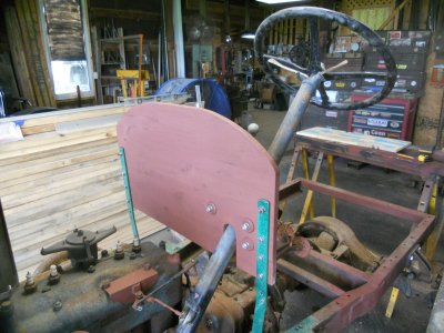
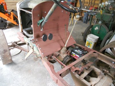
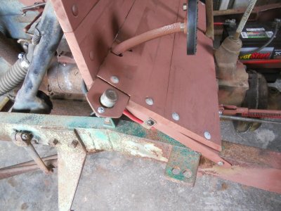
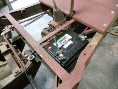
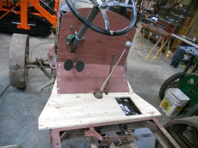
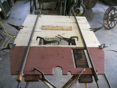
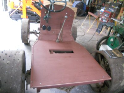
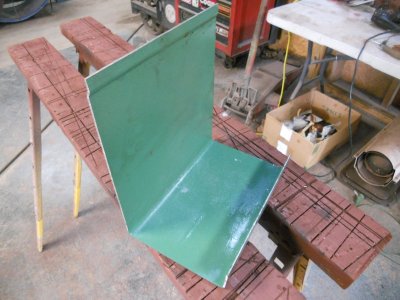
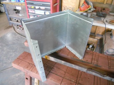
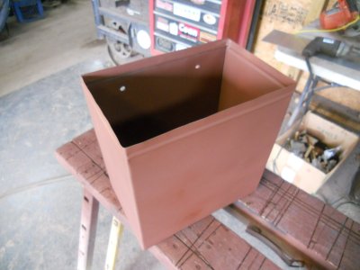
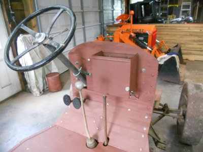
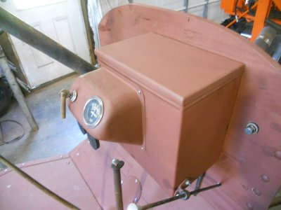
Before I can go farther on the brake, I need to make and mount a dashboard.

DSCN3351.JPG


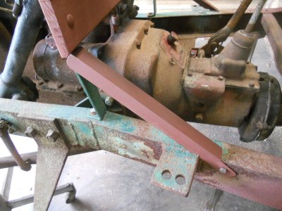
Then angle iron brackets are made up and mounted on each side at an angle for this part of the footboard.

DSCN3353.JPG


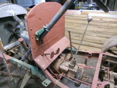
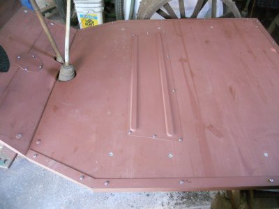
The upper half of this footboard is mounted in place.
Both the clutch and brake pedal come up and rest against the underside of this board to keep them in place.

DSCN3354.JPG


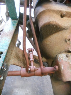
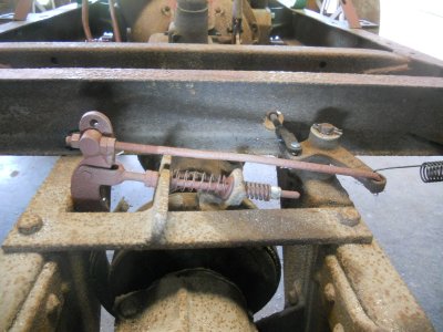
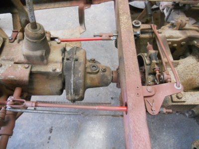
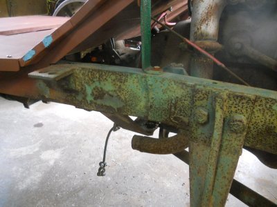
This is a better view of both the parking brake linkage and the brake pedal linkage.
The end of the linkage rod from the brake pedal ( on the left ) is adjustable get the correct tension when using the brake pedal.

DSCN3355.JPG


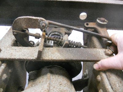
Because both of the operating linkage rods pull to engage the brake there has to be a provision for each linkage to float when the other linkage rod is used.

Here I have pulled the parking brake lever back to engage the drum brake.
You can see that the metal tube on the brake pedal linkage rod has slid forward on that rod.

DSCN3358.JPG


With the brake pedal pushed down, you can see that the long bolt that is attached to the left end of the right angle bracket has slid out thru the metal tube that is on that linkage rod.

DSCN3360.JPG
 
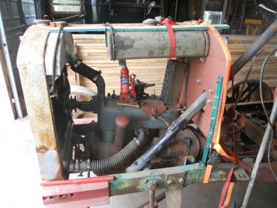
Figuring out how to mount the gas tank.
I have it blocked up in place so the top of the tank will sit up against the underside of the hood.

DSCN3363.JPG


Here is the finished tank mount.
This has to have two upper radiator supports so I made the front gas tank mount so it bolted onto them.

DSCN3364.JPG

DSCN3365.JPG


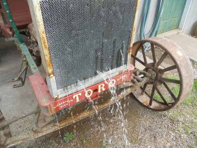
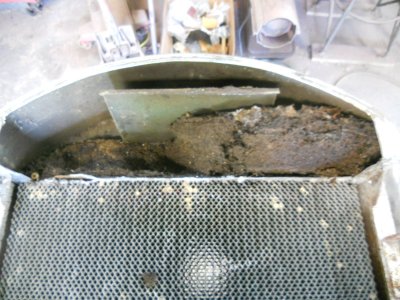
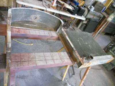
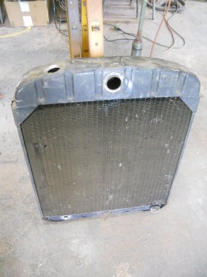
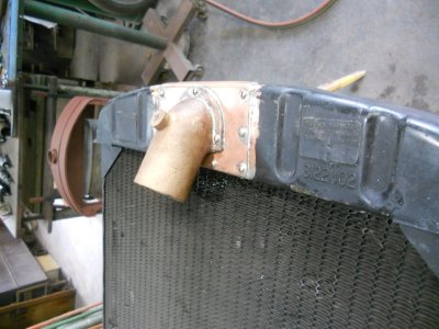
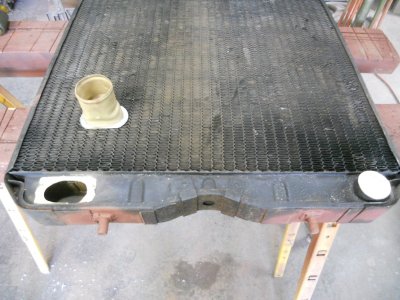
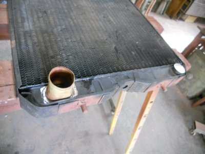
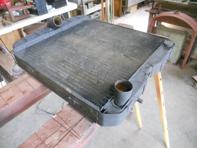
While I have it sitting outside, it would be a good time to do the wet test.
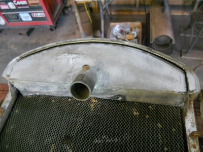
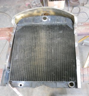
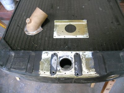
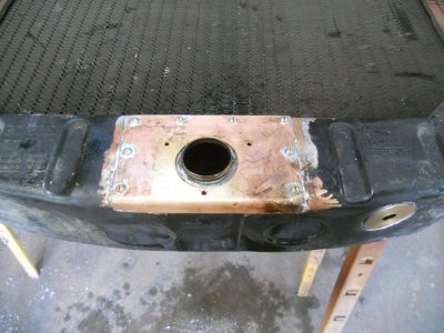
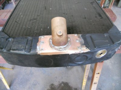
I figure this radiator would work better as a shower head then it will as a radiator.

DSCN3367.JPG
 
Back
Top