4 wheel steering trailer

MacWorld

Tractorologist
Member
Here is a new project I am working on. My girlfriend loves flowerbeds and makes new ones often so she needs to use soil and mulch. I always keep a pallet of mulch around but I store it far and at a place where there is a lot of mosquitos/flies so I will build a trailer to have those easy to bring to were she is working.

The trailer will be for off-road use only with the wheels "in the corners" so it stands and we don't have to lift it to hook/unhook. The trailer will be flat with the bottom made of expanded sheet metal on which I want to be able to drop a complete 4x8 sheet of plywood. The outside dimensions of the trailer will therefore be around 48.5" x 96.5". I already bought 4x 15x6.50-6" cheap wheels on Amazon for this trailer and I want to make it 4 wheel steering. Is it really required? No but I want the challenge.

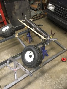
Here is where I am at currently, a lot of the steering parts are made
IMG_8519.jpg

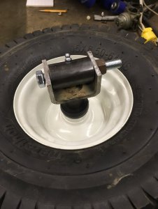
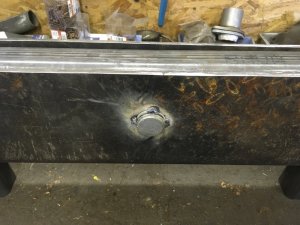
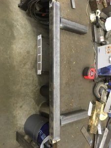
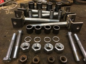
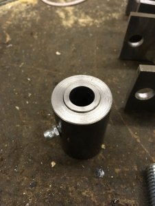
The vertical axle will be a 0.5" ID 0.75" OD tube inside a 0.75" ID 1.25" OD tube welded to the axle and the wheel "hub" will attach with a .5" bolt. The 0.5" ID 0.75" OD tube is a bit over 2" and the bigger one is 2". Oh also the bigger tube will have a grease fitting and the inner one has a groove to help the grease to turn around it between the tubes.
IMG_8520.jpg

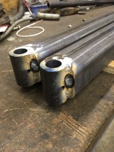
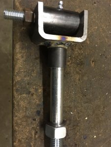
The U part is actually a 2x2 receiver hitch tube that I cut lengthwise to get my profile, I had this laying around from a previous project therefore I only needed to cut it to length. I must say this will be the weak point of the steering IMO.
IMG_8521.jpgIMG_8522.jpg

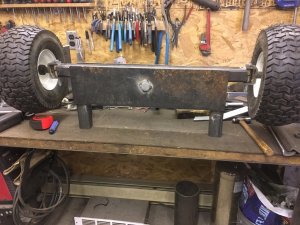
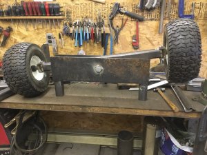
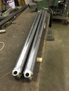
The axle is 2x2x0.25" square tubing (overkill but I had 24' of it).
IMG_8523.jpgIMG_8524.jpg

My next step will probably be to make the "A" frames to support both axles, the rear one will be rigid but the front one will be on an axle to conform to the landscape a bit, the same way most garden tractor are setup.

For the steering it will be based on Ackermann and the front and rear steerings will be linked together; When the trailer gets pulled in a curve to the left the rear axle will steer right, this way the rear wheels will follow exactly the same tracks as the front wheels. It's working this way for the carts carrying the luggage at airports.

The thing I don't fully know yet is how to make a Ackermann steering for a 4 wheel trailer. For a garden tractor or something simple as this the Ackermann principle is that the outer tie rod end are bolted on a "line" from the wheel vertical pivot to the center of the rear axle. I've found documentation for 4ws wheelchairs stating that in this case the "line" is from the vertical pivot to the center of the chair but I don't know if this applies to a trailer. Here is the documentation if someone is curious: Optimizing the turning radius of a vehicle using symmetric four wheel steering system look at the 2 last pictures to understand what I am trying to explain.

I'll update when I make progress
 
Sounds like a good thread to lurk on!
 
Sounds like a good conversion for the JD All Wheel Steer GT's. Have fun with that project, will be watching.
 
How's this project going?

"Sadly" I had no time to put on this project lately... I've been given 2x 2post auto lifts by a friend who had to replace them and I am restoring them before installation. Since they take so much space when disassembled, I am prioritizing this project ahead of the all the others. Once the columns will be bolted to their final spot (even if not working), I will be working on the other projects. At least now (I mean 15 minutes ago at the time of writing) I finished sanding down to the metal all the parts. I removed about 8 litres (2 gallons?) of paint in powder! Long live band sanders! The columns have one coat of paint since last weekend and I'll soon get back on their second coat.

I guess I never have too many projects going on!
 
Dusting off this thread a little bit! With the current pandemic lock down I've had more time to work on my projects and I'm working on this one with many other. I've progressed a bit "fabrication side" but I'll post that later, for now here is what I ordered on eBay from China. Everywhere else it was twice the price or more and I don't want to spend a fortune on this trailer so I am ready to wait the 17 to 60 days shipping delay anyway my project doesn't progress too quickly as I always work on many at the same time.

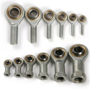
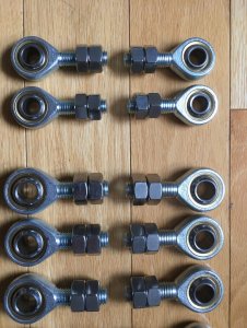
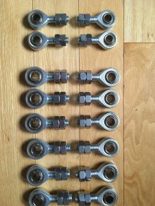
I've ordered the male version of those (top row), 6x left hand thread and 6x right hand thread, all of those M14x2.00 size. I also ordered 2x LH and 2x RH in M12x1.75 size for my 1655 but that's for another thread :)
s-l1600.jpg

Why 6 of each? Well I need 6 tie-rods total, one from the... DAMN! I just realized I needed only 5 tie-rods! Well I'll have backups... I need one tie-rod from the trailer's tongue to one of the front wheel spindle then I need one tie-rod between all 4 wheel spindles and the mechanism that will transfer the front axle movement to the rear axle. Keep in mind the remaining of this post will be wrong in the number as my orders are already paid.

Why metric? Well first I'm not a fan of imperial measurements but I won't stop myself for that. I simply couldn't find anything from China in imperial (except from the US the world is all metric I guess it plays a big part for that) and buying imperial tie-rod ends from the US was ridiculously expensive.

If someone wants to search for those over the Internet, here are the numbers work
SA prefix means male thread (top row in the picture)
SI prefix means female thread (bottom row in the picture)
then nothing or L, L for left hand thread, nothing is standard right hand thread
next the size in millimetre in the following: 5, 6, 8, 10, 12, 14, 16, 18, 20 (it's at the same time the thread size and the hole size BTW)
then always T/K

Therefore what I ordered were the following
6x SA14T/K
6x SAL14T/K
If anyone wonders, the seller I chose (he had a complete inventory and replied quickly to my questions) is named avatardeal

Why 14mm size for the trailer? I considered 12mm (a bit under 1/2") as the minimum but the 14mm were not that more expensive than 12mm and the 16mm were quite more expensive than 14mm.

Why male versions of the tie-rod ends?
- I considered ordering LH and RH threaded rods and weld them together but those are quite expensive even if I would use only a small part each end and weld a plain rod or tube in the center.
- I considered the fact that I have a metric lathe, I could have turned nuts/bungs or threaded rods but this is time consuming and the thread turning tooling is quite more expensive than nuts. Also I would have needed jam nuts anyway!
In the end I think it's easier to build "tube tie-rods" from plain tube and weld standard hex nuts to the ends.

To build the "tube tie-rods", I ordered nuts. I ordered twice the number of tie-rods as for each tie-rod end I need a welded nut for the tube and a jam nut. I don't know why (and don't complain) but it was often cheaper to buy stainless steel and there was way more choices than plain steel.. weird but I can't complain about that! I ordered:
13x M14x2.00 right hand nuts
13x M14x2.00 left hand nuts
5x M12x1.75 right hand nuts
5x M12x1.75 left hand nuts
All of those 304SS as the 201SS was not really less expensive and to what I know 201SS is still prone to rusting. I ordered 1 extra for each as to have backups just in case... not a big backup but oh well.
For those the seller is glhk04

As you may guess I won't be able to make progress on the tie-rods for at least 2 months due to the shipping delay. In the mean time I have other parts to work on and if I get to needing tie-rods I can make quick and dirty ones from wood.
I hope some of you read through all of this and appreciated the level of details I put in there. May be someone found this post to be entertaining during the current lock-down?
 
I have absolutely no idea, I guess it will be awkward at first but eventually we can get the hang of it, same as learning to back-up a standard trailer the first time. On the other hand the main goal of this kind of trailer is really to go forward and keep the same track as the tractor (or trailer in front) as to maneuver around obstacles, not really to go backward.

We would have to ask around at airports, to what I know most luggage carts are 4 wheel steering, may be someone tried backing one of those trailer at a time. I guess backing out a long trailer train might be close to impossible.

Also I am thinking of making a feature to disconnect the rear and front wheels and lock the rear wheels straight to help backing up. I don't know if I'll build such mechanism but I am thinking about it.
 
Dusting off this thread a little bit! With the current pandemic lock down I've had more time to work on my projects and I'm working on this one with many other. I've progressed a bit "fabrication side" but I'll post that later, for now here is what I ordered on eBay from China. Everywhere else it was twice the price or more and I don't want to spend a fortune on this trailer so I am ready to wait the 17 to 60 days shipping delay anyway my project doesn't progress too quickly as I always work on many at the same time.

I've ordered the male version of those (top row), 6x left hand thread and 6x right hand thread, all of those M14x2.00 size. I also ordered 2x LH and 2x RH in M12x1.75 size for my 1655 but that's for another thread :)
View attachment 25343

Why 6 of each? Well I need 6 tie-rods total, one from the... DAMN! I just realized I needed only 5 tie-rods! Well I'll have backups... I need one tie-rod from the trailer's tongue to one of the front wheel spindle then I need one tie-rod between all 4 wheel spindles and the mechanism that will transfer the front axle movement to the rear axle. Keep in mind the remaining of this post will be wrong in the number as my orders are already paid.

Why metric? Well first I'm not a fan of imperial measurements but I won't stop myself for that. I simply couldn't find anything from China in imperial (except from the US the world is all metric I guess it plays a big part for that) and buying imperial tie-rod ends from the US was ridiculously expensive.

If someone wants to search for those over the Internet, here are the numbers work
SA prefix means male thread (top row in the picture)
SI prefix means female thread (bottom row in the picture)
then nothing or L, L for left hand thread, nothing is standard right hand thread
next the size in millimetre in the following: 5, 6, 8, 10, 12, 14, 16, 18, 20 (it's at the same time the thread size and the hole size BTW)
then always T/K

Therefore what I ordered were the following
6x SA14T/K
6x SAL14T/K
If anyone wonders, the seller I chose (he had a complete inventory and replied quickly to my questions) is named avatardeal

Why 14mm size for the trailer? I considered 12mm (a bit under 1/2") as the minimum but the 14mm were not that more expensive than 12mm and the 16mm were quite more expensive than 14mm.

Why male versions of the tie-rod ends?
- I considered ordering LH and RH threaded rods and weld them together but those are quite expensive even if I would use only a small part each end and weld a plain rod or tube in the center.
- I considered the fact that I have a metric lathe, I could have turned nuts/bungs or threaded rods but this is time consuming and the thread turning tooling is quite more expensive than nuts. Also I would have needed jam nuts anyway!
In the end I think it's easier to build "tube tie-rods" from plain tube and weld standard hex nuts to the ends.

To build the "tube tie-rods", I ordered nuts. I ordered twice the number of tie-rods as for each tie-rod end I need a welded nut for the tube and a jam nut. I don't know why (and don't complain) but it was often cheaper to buy stainless steel and there was way more choices than plain steel.. weird but I can't complain about that! I ordered:
13x M14x2.00 right hand nuts
13x M14x2.00 left hand nuts
5x M12x1.75 right hand nuts
5x M12x1.75 left hand nuts
All of those 304SS as the 201SS was not really less expensive and to what I know 201SS is still prone to rusting. I ordered 1 extra for each as to have backups just in case... not a big backup but oh well.
For those the seller is glhk04

As you may guess I won't be able to make progress on the tie-rods for at least 2 months due to the shipping delay. In the mean time I have other parts to work on and if I get to needing tie-rods I can make quick and dirty ones from wood.
I hope some of you read through all of this and appreciated the level of details I put in there. May be someone found this post to be entertaining during the current lock-down?
Thanks for taking the time.
And don't feel bad about having an extra this or that... Better that than waiting for the replacement for the one defective part.
 
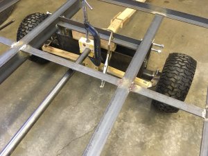
Quick update with more pictures this time, I've made some progress on the front axle which is on a central pivot point and the rear one which will be fixed.
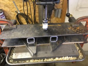
With the size of my wheels (15x6.50-6) and allowing for a up-down movement of 2" for the front tires I've established the height of the trailer in relation to the axle to be 9" therefore I cut myself 2x 7" legs for front and 2x 9" legs for the rear. The 2 short front legs will be welded together with 2 1/4" (had that lying around) plate 6" high and 24" wide. I added some 1/4" spacers both side of the legs to space out the plates as I will probably send the trailer to be galvanized and I will rivet 1/8" thick plates on the axle and on the plates as to prevent the galvanized parts from rubbing on each other and removing the galvanized coat. I know this is overkill, I can't resist. I'll probably use one 1/8" stainless plate and the other one will be brass. This way both won't rust and I won't risk cold-welding if I would have used stainless on stainless.

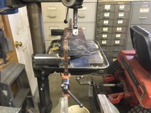
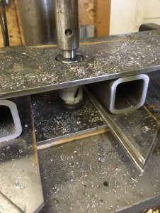
Sadly I didn't take pictures before starting to weld the front axle but as it's quite simple I guess it should be easy to understand. The first pictures show when I was drilling the holes for the main pivot which will be a 1" rod I found on the grass this spring, I think it's some kind of a crane part as it is pretty damn hard!

IMG_9661.jpgIMG_9662.jpgIMG_9663.jpgIMG_9665.jpg

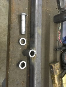
Here is the 1" pin in question, by chance it's exactly the right length I needed! I've made myself some bushings I will be welding to the 1/4" plates as to have more bearing area and one of them will have a slot cut in it and the cotter pin keeping the 1" pin from going out of the hole will also prevent it from turning, I want the axle to turn on the pin and not the pin to turn in the short bushings as I will add a grease fitting to the axle bushing
IMG_9666.jpgIMG_9667.jpg

Here what it looks like, you can clearly see the 1/4" gap on both size between the plates and the axle, I'll install the shims at the ends.
IMG_9668.jpgIMG_9669.jpgIMG_9670.jpg

And the oh-so-complicated rear axle, I wonder if it's even worth the picture :)
IMG_9671.jpg

Now I was going to weld the axles with the main frame when I realised I really undersized the trailer's main frame. I bought 1.5x1.5x3/16 angle for the whole structure but with the span between the axles which will be 6' and only my weight (and I'm not heavy!) on those angle I can deflect them, I don't think this is enough as I would like the trailer to hold 500kg (~1000lbs). I didn't calculate the exact numbers but the trailer will have to be able to hold one skid of wood mulch and at least 4'x4'x24" of soil.

Currently I plan on upgrading to 2x3x3/16 angle for the main frames (on the 8' length) with the 3" side vertical and keep the outer perimeter made with 1.5x1.5x3/16 with cross-braces to hold the perimeter to the main frame. The hard part will be to figure out how to buy steel with the current lock down!

At the moment this stalls me a bit on working further on the steering, I need to have a "strong enough" frame too be able to test the steering as I don't know exactly how to setup the Ackermann arms.
 
One thing to think about, how will a pivoting front axle affect the geometry of the four wheel steering.
Yeah that also I've put a lot of thought when I was figuring out the height of the pivot and the height of the point where the tie-rod will attach to the spindles. I don't think I have a perfect solution but I wonder to which extent it would be possible to find one with such a simple geometry and without using some kind of a rack and pinion system, there is always a relation with the rear axle involved.

I've chose to place the axle pivot point close to the axle and I will also instal the tie-rods at this height, I hope this way it will have a minimal impact when the ground is not level.

I could also have considered giving camber, caster or other advanced suspension geometry to the spindles but I doubt it is required for a low speed trailer mostly always running on soft surfaces. I guess we'll see!
 
I did some electrical work at a UPS distribution center one time and they had four wheel steering carts pulled behind Taylor Dunn runabouts. On those, the whole axles pivoted on the horizontal plane. The front axle was linked to the rear axle by a rod running laterally under the cart.
 
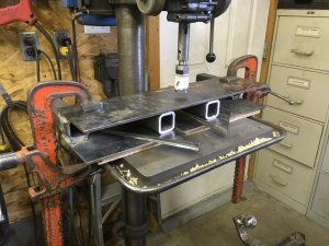
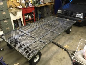
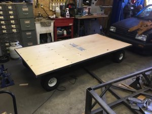
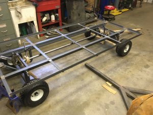
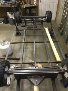
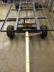
Quick update of the progress I recently made, not too many pictures for the moment as this is a simple frame. The 2 "main frames" are out of 2x3x3/16" angle and the remaining is 1.5x1.5x3/16". I don't know why but I made many mistakes and ended up with a frame too narrow in the center on the long side which prevented me from being able to lay down a full 4'x8' which was my goal therefore I had to cut out welds to fix that (that's why the small yellow/greenish rope). At the moment I have 96-1/4" x 48 1/4" on the inside, all squared up.
One thing I found out also is that even with the 2x3 main frames the trailer still is basically a flat plane structure and being on one pivoting axle at the front it is really easy to deform it. I will definitely have to find 2 springs to put at the front axle to allow for a certain un-even load without the axle moving up/down too much. The question is what spring rate would be appropriate and where to buy them in a size that fits where I want to install them (inside the vertical 2x2x1/4 posts that are right on top of the axle).

BTW the axles are bolted to the frame as to ease transportation when I'll send the trailer to be galvanized. Each corner has 2x 1/2-13 bolts and there will be diagonal braces to the main frame that I'll add later when I'll know they won't interfere with the steering components.

The plywood was only used to verify the dimensions, I want to be able to do that but the expanded steel is the real "floor".

IMG_9780.jpgIMG_9785.jpg
 
Quick teaser for tonight, I received my parts! I don't know when I'll have time to work on this project but it should be progressing in the right direction (;

IMG_9851.jpgIMG_9852.jpg
 
Well 1 month later! I progressed quite a lot but didn't have the time to post therefore here it is.

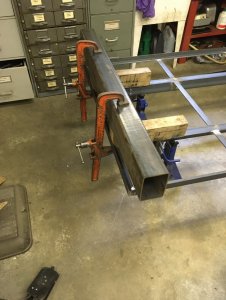
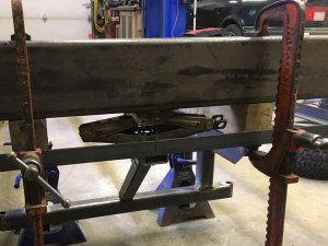
First as I added a hitch at the rear of the trailer, the rear "frame" bent because of the welds and I chose to "straighten" it a bit. Obviously this is not perfect, it's now wavy but it is not major. I made a cut at the exact center of the trailer, clamped an oversized rectangle tube I had and used a car jack to force the center away from the tube and welded it back together. Go figure why I didn't take a picture after but you get the idea.
IMG_9880.jpgIMG_9881.jpg

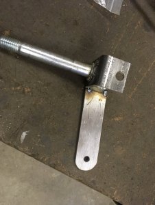
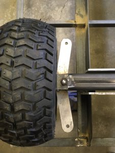
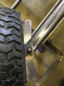
Then I finally started working on the "control arms" for the spindles, I jumped to it a bit without thinking honestly...
IMG_9882.jpgIMG_9884.jpgIMG_9886.jpg

Then I realized later that I completely forgot to even consider the "Ackerman" concept! To figure out where the holes for the tie-rod ends had to attach to I stretched a small rope from 2 diagonally opposed wheel's vertical pivot point and I got my new location this way. You may wonder what length for the arms? This isn't important for the 4 arms that are linked together, as long as they all are the same length and that the arm clears whatever might be there and that they can move turn enough. In my case my only obstacle was the front axle 1/4 plate in which the axle can pivot and I chose to make the arm stop completely flush on this plate to make this a stop. As for the turning angle of the wheels my setup allows the wheel to move nearly as much as the front wheel of my MF1655.

Creating the arms and choosing the hole's location is a bit of guess work and trial and error but it's not that hard when not rushed.

IMG_9894.jpgIMG_9895.jpgIMG_9896.jpg
 
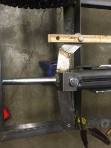
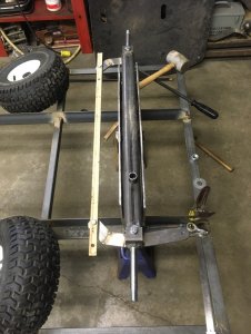
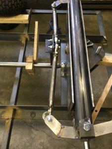
Then next step I fabricated wooden templates for the linkage mechanism to be able to see how it behaves and what length I needed for the tie-rods.

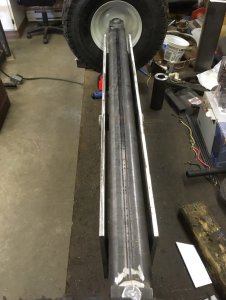
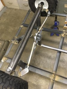
The main longitudinal shaft that links the tie-rods is a 1.250" OD, ~1" ID tube with 1" shaft welded at both ends. The shafts rest in a brass pillow block bolted to the trailer's frame on other cross-brases I added.
IMG_9914.jpgIMG_9915.jpgIMG_9916.jpg

With this I was finally able to try the trailer by pulling it myself slowly in my drive-way. I must say it feels a bit weird at first, the trailer really responds faster than we are used to with 2 wheel trailers. Backing the trailer is still manageable but you really need to consider how it behaves, i.e. you simply cannot make a standard "S maneuver" with this trailer to move it, you have to exaggerate every move and usually end with a straight movement. Hard to explain but it's easy to get the hang of it.
 
Now the actual real tie-rods!

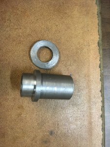
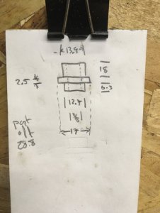
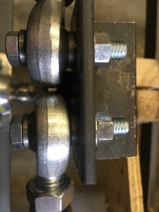
The tie-rods being metric I looked around to find 14mm bolts but I am under the impression that 14mm is kind of an odd ball size for bolts, I could have found some but I preferred to use more standard stuff. I chose to make some adapters to use 3/8" bolts and join to a 1/2" hole in the spindle arms and to include one of the spacers required on both sides of the tie-rod ends' ball.

Don't mind about the surface finish of this part, I used low-grade steel and my insert was worn out and I didn't care, the inserts are expensive enough that I preferred rough surface finish.

IMG_9945.jpgIMG_9946.jpg

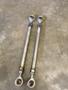
As the nuts for the tie-rods are in stainless I looked around and found just enough used 1/2" seam-less stainless pipe! I cut the pipes to have 4 identical tie-rod tubes (IIRC ~8.25" long) and a friend tacked them for me. I really need to practice myself with TIG welding!
IMG_9947.jpg

I also made "arms" on the longitudinal tube but this is simply a 1.25" 1/8" square tube with a 1.5"x1.5" 1/4" angle welded to it. Of course both ends are completely identical.
IMG_9948.jpgIMG_9949.jpgIMG_9950.jpgIMG_9951.jpg

I made a mistake again with the arm on the spindle for the main tie-rod (the one linking with the trailer's tongue), this one the hole for the tie-rod must absolutely be on the same plane from the vertical pivot of the spindle (i.e. a line from the vertical pivot to the tie-rod pivot must be parallel to the wheel). Otherwise the movement given by the tongue will be different on each side, a bit the opposite of the Ackerman steering. I even detected this (without understanding at first) while testing the trailer with the wooden linkages.

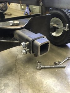
Then there is the "main" tie-rod and where it attaches to on the trailer tongue... This one is really important as it can have a ratio to get the trailer to react faster/slower depending on the angle. I decided to make this adjustable and eventually I will probably make this permanent. I used a 1" long part of receiver-hitch 2"x2" internal square tube and welded a pivot to it with 2 bolts to lock it in place. This way I'll be able to try how it reacts. In the picture the pivot for the main tie-rod can be seen under the first part of the tongue.

IMG_9956.jpg

Yesterday I was finally able to measure the main tie-rod's length (~11.25") and have it welded. This is the maximum logical length with a 1:1 ratio from the tongue to the "master" wheel. It could be logical to slow down the reaction of the trailer but not to get it faster, it's already quite reactive this way. The "reactiveness" of the trailer means that it could offset itself in relation to the tractor pulling it, ideally the trailer's center would go along the same path as the tractor's center went. Of course I have a bit of adjustment possible with the tie-rod ends and also I could cut-out the spot welds and shorten the tube if I want to slow it down more than the adjustments.

Today I should be able to try this outside behind my MF1655 :)
 
Back
Top