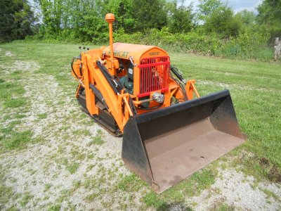
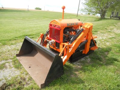
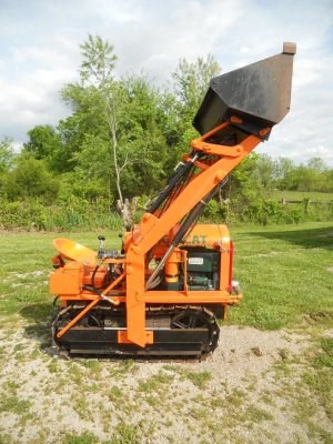
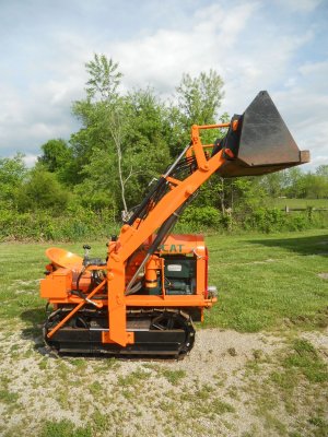
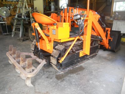
Pump looks like the ones we were putting on lift trucks.The hydraulic lines are all hooked up and the air is bled out of the system.
The loader arm is being held up by it's own hydraulic pressure.
View attachment 93460
View attachment 93461
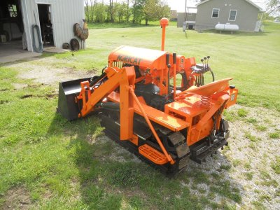
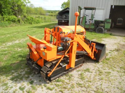
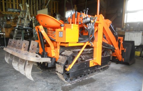
The rear hitch is also being held up by it's cylinder.
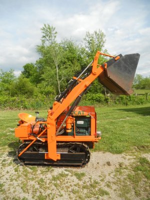
View attachment 93462
And of course, this is with the arm lowered.
I quickly realised that this pump has way too much capacity for this hydraulic system.
Just cranking the engine over on the starter alone will raise and lower the arm at a good rate of movement.
It moves way to fast with the engine running so I need to put a lower capacity pump on it.
View attachment 93463
You are using an out of date browser. It may not display this or other websites correctly.
You should upgrade or use an alternative browser.
You should upgrade or use an alternative browser.
Agricat crawler model-F
- Thread starter jdcrawler
- Start date
Most guys have the opposite problem JD with not enough pump cap.The hydraulic lines are all hooked up and the air is bled out of the system.
The loader arm is being held up by it's own hydraulic pressure.
View attachment 93460
View attachment 93461
The rear hitch is also being held up by it's cylinder.
View attachment 93462
And of course, this is with the arm lowered.
I quickly realised that this pump has way too much capacity for this hydraulic system.
Just cranking the engine over on the starter alone will raise and lower the arm at a good rate of movement.
It moves way to fast with the engine running so I need to put a lower capacity pump on it.
This pump has a 1-1/16 SAE O-ring outlet and that size is rated at about 18 GPM.
View attachment 93463
The short hydraulic cylinder that I hed mounted on the back of the crawler had leaked when I first tested it.
Turns out it has had water sitting inside it at one time and is rust pitted so it won't seal.
This is a photo of the front end loader when I had first got it.
If you look close, you can see the the that the shaft on the upper cylinder on the far side has rust pits on it.
I had replaced both of the upper cylinders with new ones.
I'm going to use that cylinder and cut it down to make a new cylinder for the back.
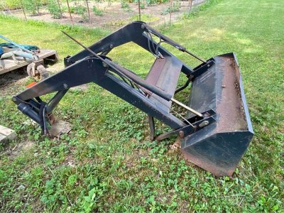
The rust pits on the far cylinder are only on the part of the shaft that was exposed.
The cylinder is welded together on the closed end.
The open end has a cap that fits up inside the tube a little ways and is held in place by a 1/8 inch diameter rod that is pushed into a slot that is machined into the side of the tube.
That 1/8 inch rod has rusted and has broken off when I tried to remove it so I can't get the end cap off.
No matter .. I cut the closed end off the tube and unfastened the nut on that end of the shaft and removed the piston so I could then pull the shaft out of the open end.
I also cut the square block for the hose fitting off and cut the weld off the solid end cap.

I'm going to re-use the solid end cap so I have turned the end down so it will fit inside the tube.
Then I cut an O-ring groove into it for an O-ring seal.
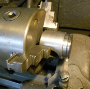
The tube is shortened and the Square block for the hose fitting is welded back on the end.
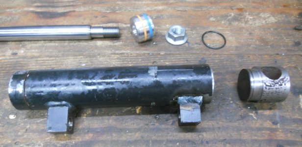
The shaft is put back in and the piston and nut are put back on.
Then the O-ring is slid onto the end cap and it is put back into the end of the tube.
This end cap is held in place with two 1/4 inch allen screws.
The cylinder is 14 inch long from center to center of the mounting holes when retracted.
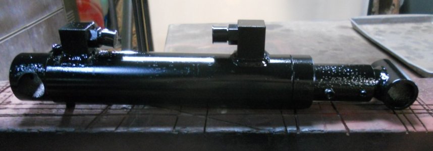
It has about 5-1/2 inch stroke.

Turns out it has had water sitting inside it at one time and is rust pitted so it won't seal.
This is a photo of the front end loader when I had first got it.
If you look close, you can see the the that the shaft on the upper cylinder on the far side has rust pits on it.
I had replaced both of the upper cylinders with new ones.
I'm going to use that cylinder and cut it down to make a new cylinder for the back.

The rust pits on the far cylinder are only on the part of the shaft that was exposed.
The cylinder is welded together on the closed end.
The open end has a cap that fits up inside the tube a little ways and is held in place by a 1/8 inch diameter rod that is pushed into a slot that is machined into the side of the tube.
That 1/8 inch rod has rusted and has broken off when I tried to remove it so I can't get the end cap off.
No matter .. I cut the closed end off the tube and unfastened the nut on that end of the shaft and removed the piston so I could then pull the shaft out of the open end.
I also cut the square block for the hose fitting off and cut the weld off the solid end cap.

I'm going to re-use the solid end cap so I have turned the end down so it will fit inside the tube.
Then I cut an O-ring groove into it for an O-ring seal.

The tube is shortened and the Square block for the hose fitting is welded back on the end.

The shaft is put back in and the piston and nut are put back on.
Then the O-ring is slid onto the end cap and it is put back into the end of the tube.
This end cap is held in place with two 1/4 inch allen screws.
The cylinder is 14 inch long from center to center of the mounting holes when retracted.

It has about 5-1/2 inch stroke.

The crawler was too fast when I had first got it running and I had put as small a sprocket as I could on the right angle drive box to slow it down.
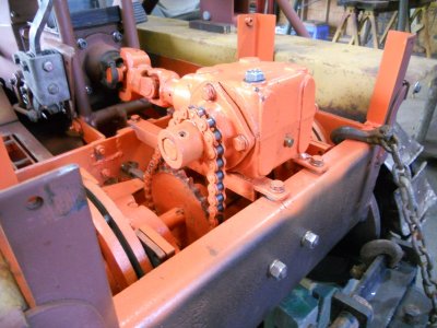
However, it is still way to fast.
In first gear, it runs the speed that I feel it should be in 2ed or 3ed gear.
It won't move the crawler at all in 3ed gear now.
So I need to figure out how to reduce the gear ratio some more.
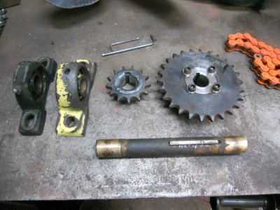
To do that, I've got together these parts so that I can make a jackshaft with different size sprockets on it.
The small sprocket is welded to the hub but the larger sprocket is bolted to the hub instead of welded.
I did this so that if I still need to make it slower, I can easily put a larger sprocket on that hub.
Here's how it looks put together.
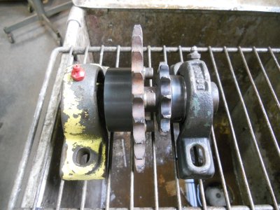
The jackshaft assembly will almost fit in the space to the left of the right angle gearbox.
I have unbolted the mounting brackets for the drive gearbox and moved it over to the right about 1/2 inch. This will be just enough so the the left mounting bracket for the jackshaft will clear the clutch & brake assembly on the left side by about 1/4 inch.
I have also taken the drive sprocket off the drive gearbox and turned to around to that it is no longer lined up with the lower sprocket.
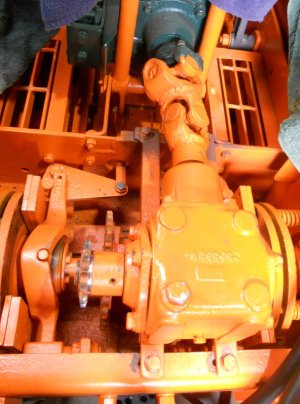
With moving the drive gearbox over that 1/2 inch, I also need to move the lower sprocket over the same amount on the axle shaft.
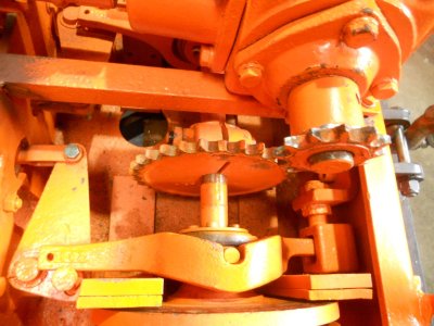
The left mounting bracket is made up for the jack shaft and bolted in place.
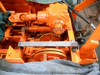
The right mounting bracket is made up but not fastened in place yet.
I have to mill slots into both mounting brackets for the mounting bolts so I can adjust the jackshaft.
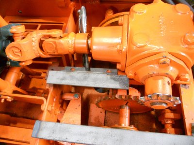
This shows how the jackshaft will fit down into this space.
The chain from the sprocket on the drive gearbox will go to the large sprocket on the jackshaft.
Then the chain from the small sprocket on the jackshaft will go down to the sprocket on the axle to reduce the final drive gearing.
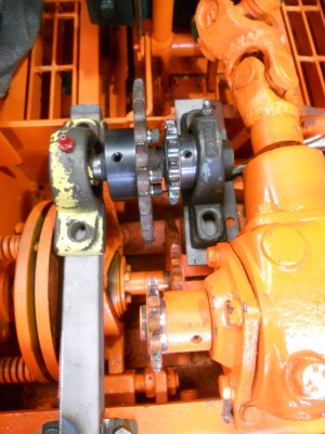

However, it is still way to fast.
In first gear, it runs the speed that I feel it should be in 2ed or 3ed gear.
It won't move the crawler at all in 3ed gear now.
So I need to figure out how to reduce the gear ratio some more.
To do that, I've got together these parts so that I can make a jackshaft with different size sprockets on it.
The small sprocket is welded to the hub but the larger sprocket is bolted to the hub instead of welded.
I did this so that if I still need to make it slower, I can easily put a larger sprocket on that hub.

Here's how it looks put together.

The jackshaft assembly will almost fit in the space to the left of the right angle gearbox.
I have unbolted the mounting brackets for the drive gearbox and moved it over to the right about 1/2 inch. This will be just enough so the the left mounting bracket for the jackshaft will clear the clutch & brake assembly on the left side by about 1/4 inch.
I have also taken the drive sprocket off the drive gearbox and turned to around to that it is no longer lined up with the lower sprocket.

With moving the drive gearbox over that 1/2 inch, I also need to move the lower sprocket over the same amount on the axle shaft.

The left mounting bracket is made up for the jack shaft and bolted in place.

The right mounting bracket is made up but not fastened in place yet.
I have to mill slots into both mounting brackets for the mounting bolts so I can adjust the jackshaft.

This shows how the jackshaft will fit down into this space.
The chain from the sprocket on the drive gearbox will go to the large sprocket on the jackshaft.
Then the chain from the small sprocket on the jackshaft will go down to the sprocket on the axle to reduce the final drive gearing.

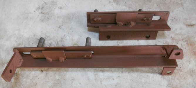
Here are the two mounting brackets with the adjusting slots milled into them.
I made up two flat steel strips with the studs screwed into them and welded on the underside.
These fit on the underside of the brackets with the studs sticking up thru the slots.
A small piece of square flat steel is welded to the side of the bracket to keep the the steel straps with the studs from falling out.
These pieces are just loose enough to let the studs move forward and backwards in the slots.
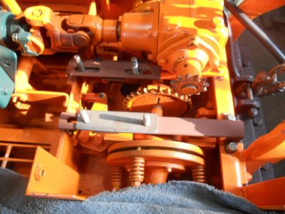
The two mounting brackets are bolted in place.
The pillow block bearing on the near side is a little shorter than the other one.
I made up a stainless steel shim to fit under it to bring it up even.
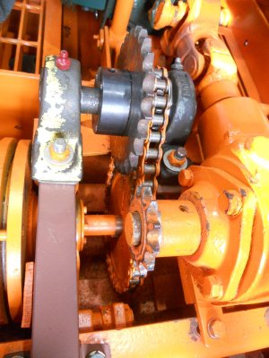
The chain going down to the axle is fastened in place.
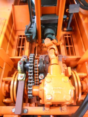
Then upper drive chain is put on.
Youtube video of test run.
I made up two flat steel strips with the studs screwed into them and welded on the underside.
These fit on the underside of the brackets with the studs sticking up thru the slots.
A small piece of square flat steel is welded to the side of the bracket to keep the the steel straps with the studs from falling out.
These pieces are just loose enough to let the studs move forward and backwards in the slots.

The two mounting brackets are bolted in place.
The pillow block bearing on the near side is a little shorter than the other one.
I made up a stainless steel shim to fit under it to bring it up even.

The chain going down to the axle is fastened in place.

Then upper drive chain is put on.

Youtube video of test run.
That would probably climb a wall now.Here are the two mounting brackets with the adjusting slots milled into them.
I made up two flat steel strips with the studs screwed into them and welded on the underside.
These fit on the underside of the brackets with the studs sticking up thru the slots.
A small piece of square flat steel is welded to the side of the bracket to keep the the steel straps with the studs from falling out.
These pieces are just loose enough to let the studs move forward and backwards in the slots.
View attachment 94994
The two mounting brackets are bolted in place.
The pillow block bearing on the near side is a little shorter than the other one.
I made up a stainless steel shim to fit under it to bring it up even.
View attachment 94988
The chain going down to the axle is fastened in place.
View attachment 94989
Then upper drive chain is put on.
View attachment 94990
Youtube video of test run.
Incredible work.
Nice load there. I wonder how many other show goers can say they built thier tractors and the truck they came on.

