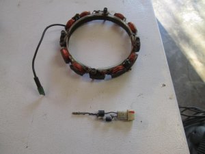
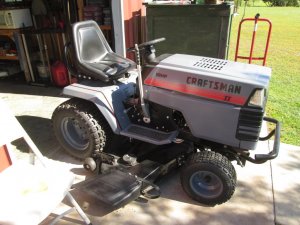
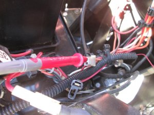
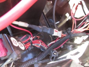
Craftsman GT18 Electrical help needed

The switch checks are in the diagram.
Ignition Switch
OFF = M and G are connected
ON - B and L are connected
START- B and S ate connected

PTO Switch
OFF - B and E - C and D are connected
ON - B and A are connected

Make sure non of the connectors are grounded to the metal case. Except the G terminal

Do you have a metal or plastic dash? I have both.
 
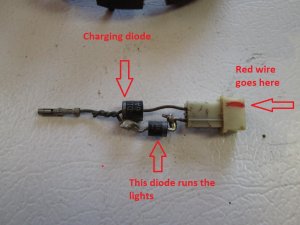
To check the diode assembly.

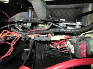
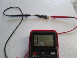
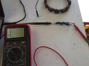
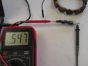
  • Remove the assembly, mark where the Red wire connects (See figure 2) Pictures are below the videos
  • Set your multimeter to the lowest OHM setting to test diodes.
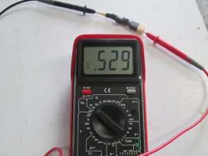
  • Place the black lead into the single connector (See figure 2)
  • Place the Red lead on the dual connector where the Red wire connects (See figure 2)
  • Observe reading on multimeter (Should be around 0.5 OHMS)
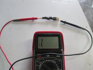
  • Reverse multimeter leads (See Figure 3)
  • Observe reading on multimeter (Should read an Open)
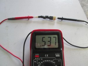
  • You can check the other diode the same way (Figures 4 and 5)
  • Readings should be reversed.
My videos that may help.

Introduction to the multi-meter


Test an ignition switch


Using a diagram


Charging circuits


Attachments

  • 1.jpg
    1.jpg
    104.5 KB · Views: 8
  • 2.jpg
    2.jpg
    75.7 KB · Views: 8
  • 3.jpg
    3.jpg
    74.3 KB · Views: 7
  • 4.jpg
    4.jpg
    73.9 KB · Views: 8
  • 5.jpg
    5.jpg
    70.7 KB · Views: 13
  • 6.jpg
    6.jpg
    132.2 KB · Views: 15
  • 7.jpg
    7.jpg
    121.8 KB · Views: 14
First, that is a phenomenal post Larry! Thank you!

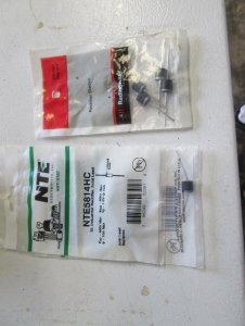
Seeing I fried the diode assembly I will have to make new one and try what you have above.

So instead, I grabbed the switch again to test with multimeter in Ohms position. Each pin has correct continuity, but watch the video. The readings are the same for each connection.

 
Last edited:
Dirty contacts will cause the readings to jump all over. Try this trick. Use alligator clips on the multimeter leads. The alligator clips have serrated teeth and spring clamping action that makes better contact on the connections.
 
Dirty contacts will cause the readings to jump all over. Try this trick. Use alligator clips on the multimeter leads. The alligator clips have serrated teeth and spring clamping action that makes better contact on the connections.

Don't have alligator clips, so I'll clean contacts and report back.
 
Those switches aren't that expensive. If your having doubts about it just purchase a replacement. If you think about how old it is it's probably time.
 
Larry, can't thank you enough for the help!

I ordered a new switch, should be here Sunday....we will see.

When you make your own assemblies do you just made them like the original? Where the diode lead goes directly into connector or do you add a length of wire to diode lead?
 
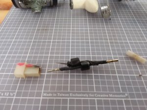
I try and make them original, I purchased heat shrink and the correct pins to solder on. Here is an experimental one. Please note the diode. Diodes are like a one way check valve. The cathode end is marked with a band. This picture shows the correct orientation of the diodes. If inserted backwards they will blow up.
 

Attachments

  • 1.jpg
    1.jpg
    95.6 KB · Views: 12
  • 2.jpg
    2.jpg
    68.8 KB · Views: 16
  • 3.jpg
    3.jpg
    127.4 KB · Views: 17
  • 4.jpg
    4.jpg
    92.2 KB · Views: 16
  • 5.jpg
    5.jpg
    84.2 KB · Views: 12
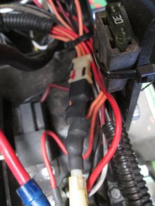
Just sat down to get started on new diode assembly and took your advice to mark red wire., interesting, mine is backwards from yours. In the pic you can see the stripe on the diode and out may be backwards. So, after i make new one I'm going to hook it up and test which is giving me which dc output and make sure is right!

20190420_063624.jpg
 
Yes, I would deffinately test it. Hook the stator wire up and measure each pin. I'll check mine later and post what I get. One should read a positive reading the other a negative reading.
 
You may be right on the reversed thing. My wires are faded so the red and orange look the same. my red mark should be on the other diode.
 
I did some testing on mine. Hulk II was re wired a while back and I used Orange to go to the switch and Red for the lights, Here is the connector corrected. Red = charge, Black = lights. I am working on a video to show more detail.
 

Attachments

  • backwards2.jpg
    backwards2.jpg
    130.3 KB · Views: 7
Corrected multimeter readings for the charge diode. I have to run to town, I'll check back this afternoon.
 

Attachments

  • 001.jpg
    001.jpg
    64 KB · Views: 4
  • 002.jpg
    002.jpg
    59.8 KB · Views: 4
Couldn't leave it alone, and to eliminate any confusion I caused I ran some tests on BOH. He has two orange wires (yes I re-wired him also) but I confirmed the correct wires this time.
 

Attachments

  • 1.jpg
    1.jpg
    108.5 KB · Views: 6
  • 2.jpg
    2.jpg
    86.9 KB · Views: 6
  • 3.jpg
    3.jpg
    91.2 KB · Views: 6
Did a bunch of work, but no chance to start it up yet, running a fine balance of keep wife happy, keep baby occupied, and get stuff done.

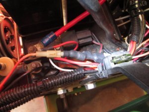
New switch installed. Tested, getting 12v on the red wire when switch on. Fuse to ammeter good. Diode in correct orientation. Now to start and check diode leads before connecting to battery.

I took all switch apart, it was pretty rusty inside. New switch does not give me readings all over the place like old switch. Really hoping problem was switch!
 
Back
Top