Free tractor

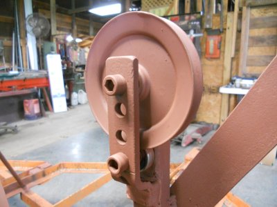
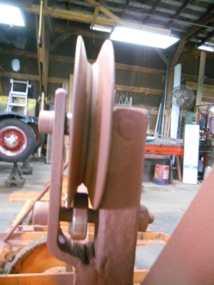
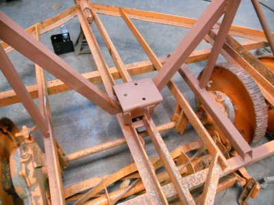
The other cable pulley stand is welded in place on the main frame.

DSCN2496.JPG


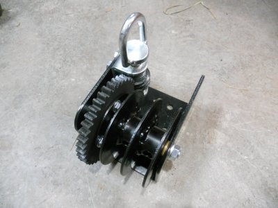
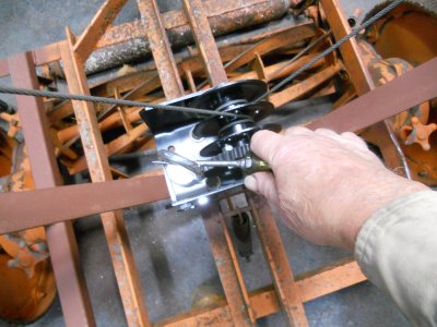
I'm using this winch to raise and lower the outriggers.
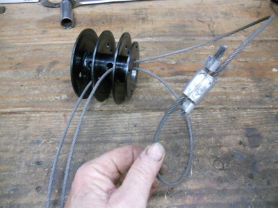
Note that it has two separate spool areas so each cable has its own spool to wind up on so the two cables won't get snagged together.

DSCN2497.JPG


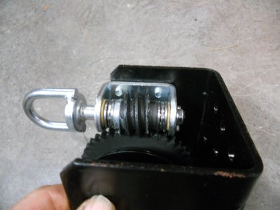
This winch is driven by a worm gear so the cable is controlled at all times and it can't slip and run out like it can on some hand winches.

DSCN2498.JPG


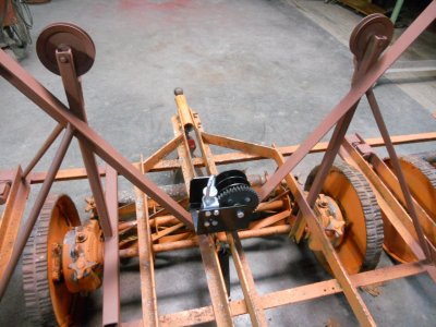
The winch will set down in the center like this with the drive gear shaft pointing straight up.

DSCN2500.JPG


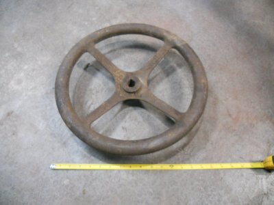
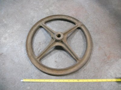
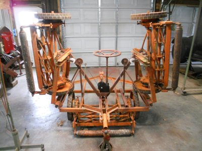
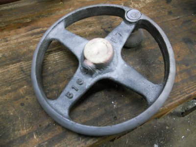
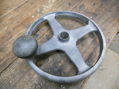
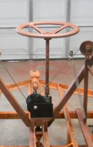
I'll bring a shaft straight up from the winch and put this 16 inch diameter cast iron wheel on it.
This wheel will be about 40 inches off the ground so I can stand in front of it to operate it without having to bend over or kneel down.

DSCN2501.JPG

DSCN2502.JPG


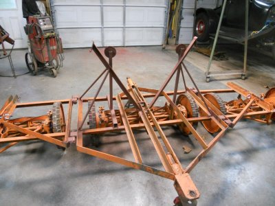
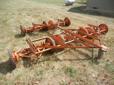
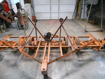
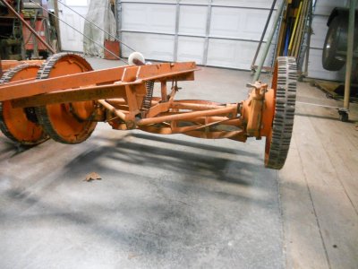
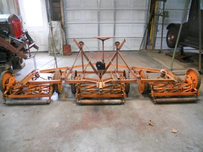
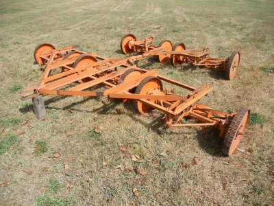
As a reminder, this was a complete pull behind mower with three reels in front and two reels behind to cover the uncut areas left between the three front reels.

DSCN2272.JPG


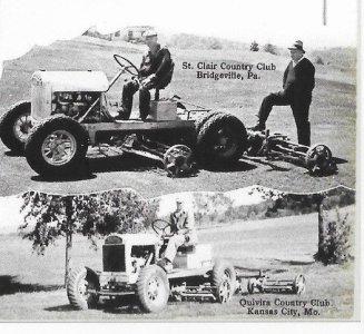
Now, just the three reels will be pulled behind and I'll take the other two reels and mount them under the tractor like is shown in this old photo of a Toro model-A tractor.

Toro - short tractor-1.jpg
 
Last edited:
While getting ready to mount the winch, I realised that my idea of using two seperate cables to lift the two outriggers won't work right.
Cables seldom wind up on a spool the exact same way every time.
It's very likely that one side will be pulled up tight against it's stop pad before the other one has come up against its stop pad and the winch won't turn anymore.
Traveling down the road, that loose outrigger is going to be jerked in and out and something could possible break and let that outrigger fall out into the other lane of the road.

So I decided that instead of a seperate cable on each outrigger, I need to use one cable to lift both outriggers so it can pull both of them up tight against both stops every time.
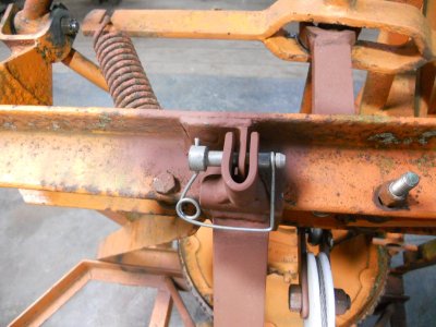
I'm also going to put a locking pin on each stop to hold the outriggers in place and not rely on just the cable to do that.

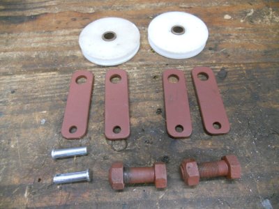
I made up these parts today.

DSCN2508.JPG


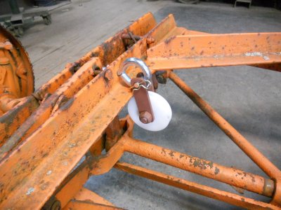
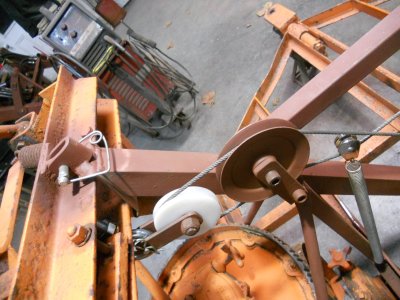
These make up a pulley that is fastened to the 1/2 inch I-bolts ( where the single cable would have attached ).

DSCN2510.JPG


Then I added a small bearing under the two cable lift pulleys.

DSCN2511.JPG


These small bearings are set up into the " V " so the cable can be run over them and be kept in place by the sides of the " V ".

DSCN2512.JPG


This is the mounting pad for the winch.

DSCN2513.JPG


The two ends of the one cable are fed thru two holes in the spool and on out the hole in one end so they can be fastened together with a crimp clamp.

DSCN2514.JPG


The cable is pulled back out so the crimp clamp is now inside the spool.
The spool is put back on the winch and the winch is bolted onto the mounting pad.
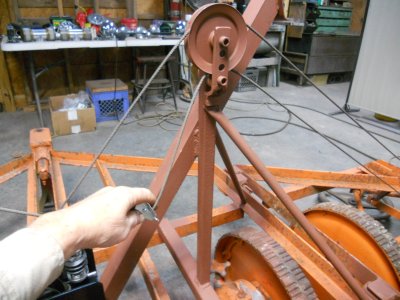
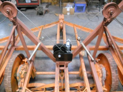
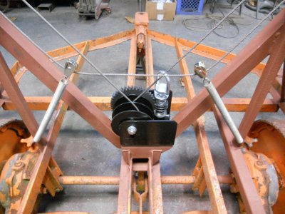
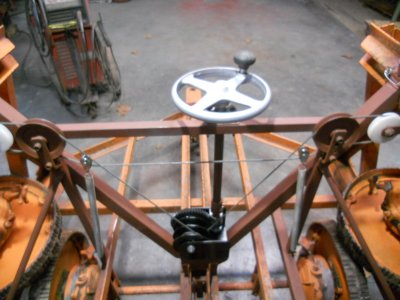
The single cable is run thru all the pulleys.

DSCN2515.JPG


The two small pulleys hanging in the center of the cable going across between the two lift pulleys are going to have springs attached to them.
These two small pulleys will pull that area of the cable down to constantly take up any slack in the cable.

DSCN2516.JPG


I'm using a small screwdriver to turn the handle on the winch.

DSCN2517.JPG


Without very much effort at all, the winch easily started picking up one of the outriggers so using that cast iron 16 inch wheel will work just fine.
Another advantage of using a single cable is that it will lift one outrigger at a time which will take half the effort of lifting both outriggers at the same time.

DSCN2518.JPG
 
Did a test run today.
I'm amazed at how easy this winch cranks the outriggers up and down.
I got a little tired spinning my hand out around the 16 inch diameter wheel so I'm going to switch to a much smaller wheel so I don't have to turn my hand out around so far.

There will be a bar going across with a bearing on it to support the crank wheel when it's all finished.

DSCN2521.JPG

DSCN2522.JPG
 
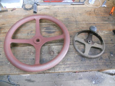
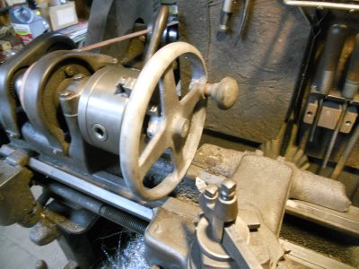
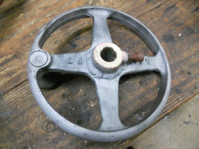
Here is the smaller steel wheel that I'm going to use instead of the big wheel.
You'll notice that the center boss on the smaller wheel isn't much bigger than the hole in the other wheel.

DSCN2523.JPG


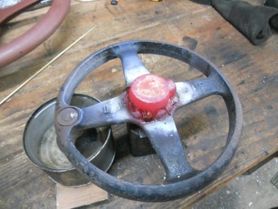
I have welded a larger ring of metal onto the back side of the wheel and then I filled in the center hole with braze.
This wheel has a bakelite spinner on it that can't be removed so I have it sitting a can of water so it doesn't get too hot while I heat up the center hole enough to melt the braze into it.

DSCN2524.JPG


After sandblasting.

DSCN2525.JPG


There is just enough clearance for this wheel to fit on my lathe.

DSCN2526.JPG


The center hole is bored into it.
The piece that I used for the center is an old heavy duty I-bolt and the stub of the " bolt " makes an excellent boss for drilling and tapping for the set screw.

DSCN2527.JPG

From what's left of the center boss on the front side, you can see why I needed to add material on the back side.

DSCN2528.JPG
 
The lift mechanism on the reel mowers is finished.
The weather is still going to be good for awhile yet and I'm still waiting on parts for my other two projects so I decided to pull the Toro model-A tractor in and get it stripped down to start on working on it.

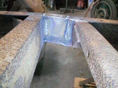
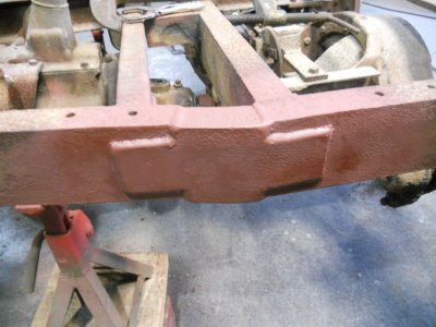
The first thing I want to do is to get the frame shortened up.
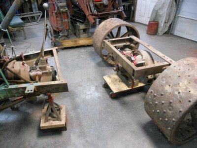
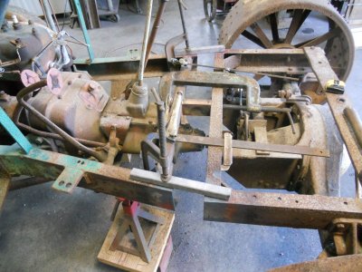
I have both sides of the frame resting on jack stands so it won't drop down when I cut the rear frame rails.
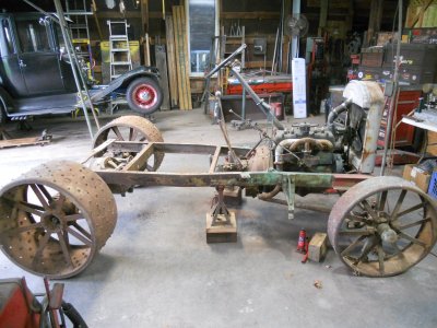
DSCN2531-1.JPG


I've wedged two blocks of wood against one of the front wheels and they are held in place with a tie strap so the front of the tractor can't move.
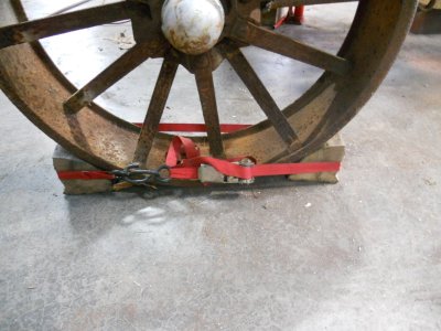
DSCN2531-2.JPG


I want to shorten up this frame so it is about the same length as this Toro model-A tractor.
This tractor is the same year range as my tractor and when I first saw it, I didn't know if it came from the factory that short or if someone shortened a long tractor like mine.
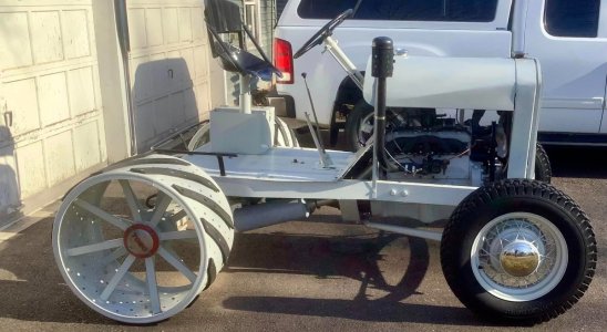
Toro model-A tractor.jpg


Since then, I've come across a couple of other short Toro model-A tractors so I'm thinking they built some that way at the factory.
I also found this old photo of a short Toro tractor.
This one is a little newer, possibly in the 1930's, but it shows the the factory did make two lengths of tractors back then.
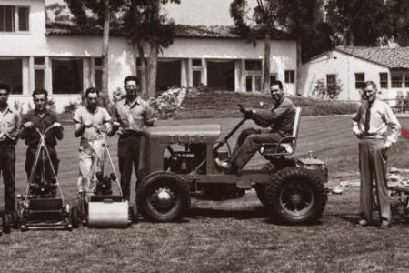
Toro short tractor -5.jpg


The driveshaft is taken out.

DSCN2531-3.JPG


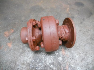
The driveshaft has a unique inclosed universal joint on each end.
This is the front end of the driveshaft.
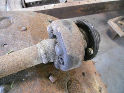
DSCN2532.JPG


These universal joint housings can be unbolted and split into two halves.
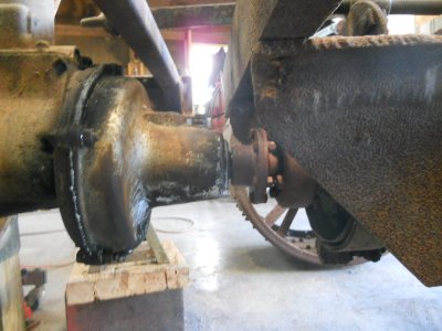
This is the half that is still mounted on the rear axle.
Incadently .. the drum with the brake band around it on the rear axle is the only brake on this tractor.
There are no brakes on the wheels at all, just this one drum brake.
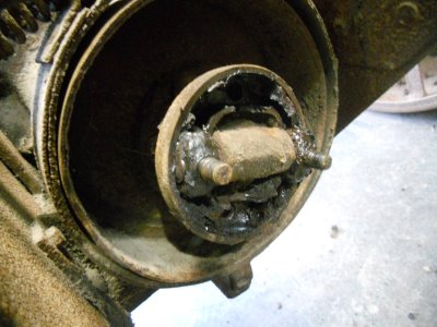
DSCN2534.JPG


The front universal joint is still nice and tight but the rear one has a lot of slop in it.
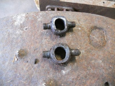
Here are two of the four caps for the rear joint.
You can see how much they are worn out of round.
DSCN2537.JPG


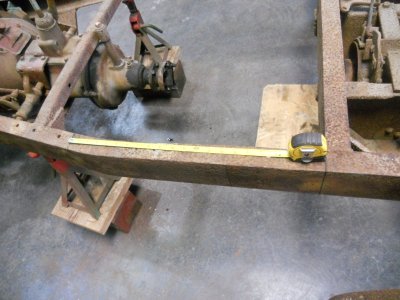
To shorten this frame up so it matches the photos of the short tractors, I'll have to take about 21 inches out of the frame.
This would bring the rear axle up so that it would attach to the transmission with just one of the universal joints ( luckily, I have one good universal joint ).
DSCN2544.JPG


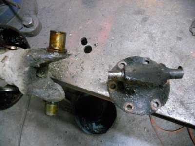
The half of the universal joint on the transmission and on the rear axle have a big hump in the center with the pins machined on each end of it.
The rear axle part of the joint is sitting on the workbench.
You can see how the two pins are worn down on it.

The front of the driveshaft is clamped in the vice and you can see that the center is notched out to fit around the hump on the other half of the joint.
You can also see how good the pins are on the front driveshaft joint.

In order to make it so I can fasten the rear axle to the transmission with one joint, I'll have to cut the big hump off the part for the rear axle.
Then I'll have to cut the end off the driveshaft and weld it onto the round plate that bolts onto the rear axle.
DSCN2546.JPG
 
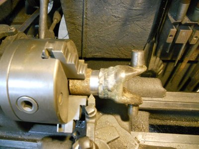
I cut the good end off the driveshaft and chucked it up in the lathe.
Then I turned a smooth surface on it.
DSCN2549.JPG


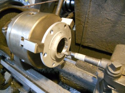
The hump is cut off the rear axle flange and that is chucked up in the lathe.
The center is bored out for the end of the driveshaft to fit into.

DSCN2551.JPG


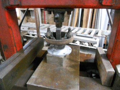
The half housing is assembled onto the driveshaft end and it is pressed into the rear axle flange.

DSCN2552.JPG


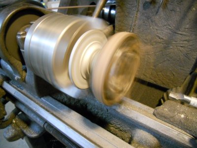
This is put back on the lathe and spun to make sure it is all concentric ( it isn't turning anywhere near as fast as it looks in the photo ).

DSCN2553.JPG


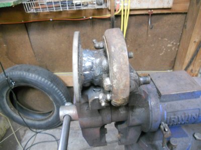
The two parts are welded together.

DSCN2554.JPG


This is the new driveshaft with a single U-joint.

DSCN2555.JPG
 
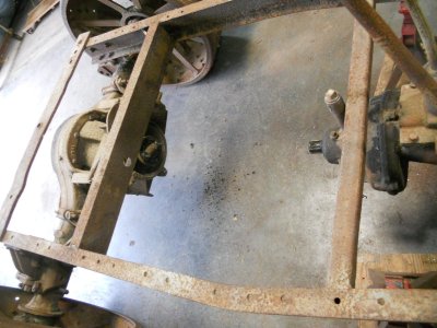
The frame is cut in two.

DSCN2556.JPG


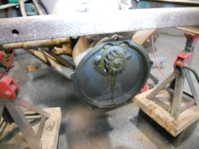
The model-A transmission has a planetary gear reduction attached to it.
Over the years, grease has leaked out of this gear reduction around the shaft for the driveshaft so I took it apart to replace the oil seal.

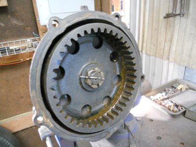
There is this small gear on back of the transmission.

DSCN2558.JPG

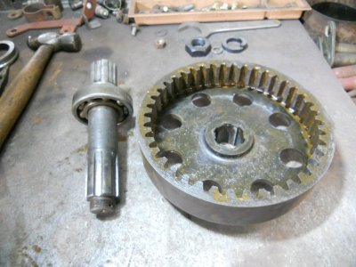
That small gear meshes with the teeth on the inside of this bigger gear for the reduction.
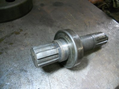
The end of shaft to the left with the threads on the end, fits into the center spline on this big gear.
This big gear also has a bearing on the other side of it so the gear and the shaft are supported by two bearings.

DSCN2559.JPG


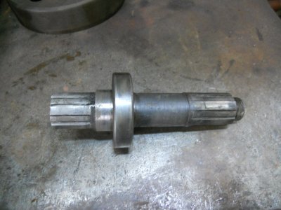
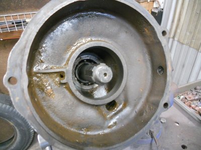
The spline on the other end, with the bearing, is what the driveshaft fits onto .
I had expected to find a oil seal in the housing on this side of the bearing but there wasn't one.

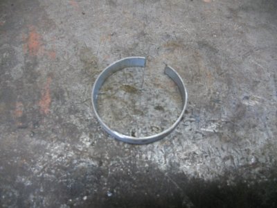
The other side of this bearing is open but this side is closed in with a metal ring.
This keeps most of the gear oil from leaking out but there is still some seepage.
There is a small gap between the center hole of the metal ring and the shaft that oil can leak out thru.
There is also a small hole drilled into the metal ring ( shown at the top ) to guarantee that some oil gets past the bearing.
This is necessary to keep the rubber lip on the oil seal lubricated.

DSCN2561.JPG


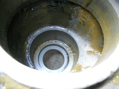
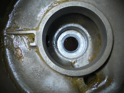
The end of the shaft with the bearing fits down into this end of the gear housing.
The bearing fits into the large counterbore and the splined shaft fits out thru the hole in the end.
In between the large counterbore and the hole in the end is another counterbore that is about 2 inch diameter and about 5/16 inch deep.

DSCN2563.JPG


I assume that originally there was an oil seal in the smaller counterbore and someone took it out at some time and didn't replace it when they put the gear housing back together.
I went down to NAPA and was able to get an oil seal to fit.
The oil seal will ride on the smooth area of the shaft just to the left of the bearing.

DSCN2560.JPG
 
Back
Top