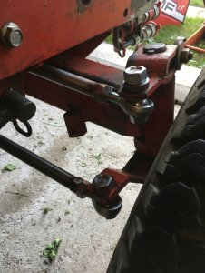
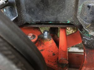
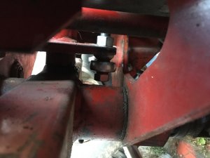
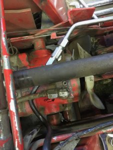
Hydraulic steering on my MF 1655

Quick update of progress, currently taking a coffee break therefore why not posting!

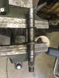
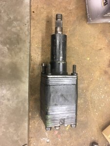
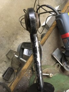
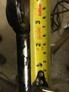
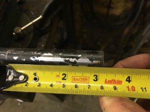
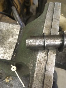
Yesterday my friend with a milling machine made me the 2 flats I needed to complete the shortening of the column. Mini column! Next step will be to get a rebuild kit.
IMG_9411.jpgIMG_9412.jpgIMG_9413.jpg

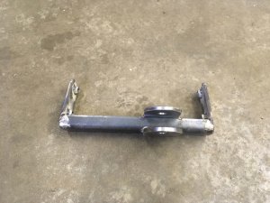
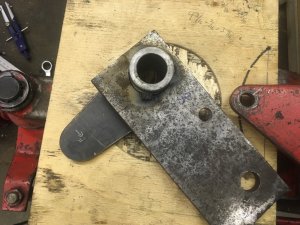
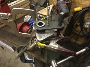
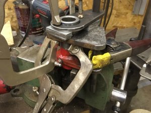
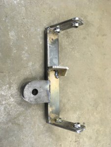
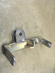
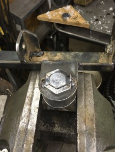
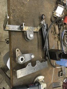
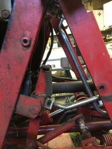
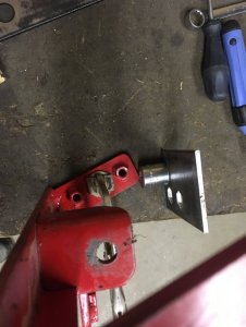
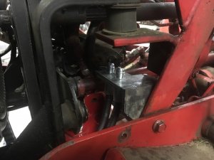
I am currently working on the cylinder installation. So far it's quite "simple", I keep on thinking the 1655/1855 were made with hydraulic steering in mind, there is so much room available where required! Again, I avoided any drilling/welding to the original parts. This bracket will bolt using the 2 front bolts of the steering "A-frame" and also the 2 rear bolts of the mower deck mount right under the A-frame front bolts. There is also a cross frame quite close where the hydraulic cylinder for the mid-lift attaches to and I might add something between my bracket and this cylinder pin but I am not convinced it would be required and it would add complexity for installing/removing my frame... I don't know.
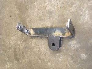
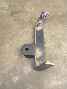
IMG_9414.jpgIMG_9415.jpgIMG_9416.jpg

BTW someone that wouldn't mind welding to the tractor could have made the 2 plates with holes a bit longer and weld them directly to the same transverse support for the mid-lift cylinder. The only drawback to doing this is that the upper plate prevents from re-installing the longitudinal rod (item #44 on last image) therefore no going back.

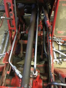
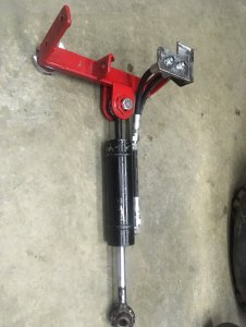
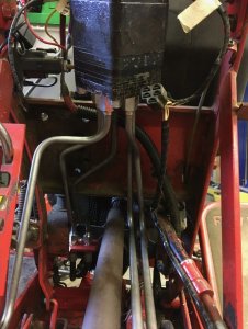
Here is the bracket with the cylinder. The cylinder will be exactly where the long rod from the steering box to the pivot on the front axle is (item #44). There isn't anything close to the cylinder there, the "closest" for those knowing this tractor will be the 2 lower pulleys for the shaft to the transaxle and the clearance will be in the 1.5" - 2" range.
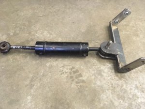
IMG_9417.jpg

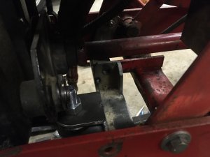
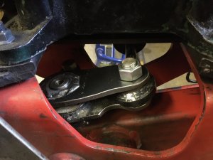
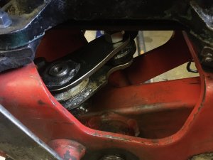
Next step will be to attach the cylinder to the "lever arm assembly" (item #28) on the front axle. Sadly the original travel of the rod is 5.5" and the hydraulic cylinder has a travel of 4.5" therefore I need to relocate the pin closer to the lever arm rotation center which might force me to build a new one. The lever arm's triangle plate will also probably have to be welded on its shaft a bit closer to the axle as to lower the cylinder away from the engine mount which is another reason why I might build one from scratch. Obviously I would prefer using the current plate while maintaining reversibility to manual steering, we'll have to see if I can manage to find a way.
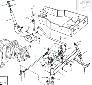
Screen Shot 2020-01-19 at 10.45.27 AM.png

I might post again later today if I have the time... at one point I will have to stop, re-assemble the tractor and get clearing my drive way!
 
But will the cylinder's stroke be fully utilized, or will the cylinder still be pushing or pulling when wheels go "lock to lock"? I placed my cylinder directly onto the front axle beam so the cylinder stroke exactly matched. Plus I wanted to take out the extra wear point of the triangular plate. Not being critical at all....just curious. Looking great!
 
Currently the stroke of the cylinder isn't long enough to use full turning "lock to lock". I decided (and started) to build a custom "triangular plate" with the correct geometry to match as exactly as possible the cylinder stroke with the "lock to lock" requirements. It will probably be a matter of moving the long rod rotation point (or now in fact where the cylinder will bolt to) something like 1/4" toward the triangle's main pivot point. Didn't do the math yet but it's not a big amount.

As for wear I must say the triangle's main pivot on my tractor has no wear at all the tolerances are tight. Otherwise it's the small arm between this triangle plate and the right wheel that could be taken out of the equation and/or oversized, I will see over time if this is required. I am not too much worried about having some slack in the direction as even when it had a lot of slack (which I corrected) I had no trouble going full speed with the tractor and keeping a straight enough direction.
 
The only steering wear on my 1650 is that darn triangle, it's not bad but it is noticeable. I replaced every other rod end. My plan is to order some shims from mcmaster car and try to take up some of the slack in it. It's wore so it will move up and down on the shaft welded to the frame.

Anyway, ideally you'd want to cut out any unneeded wear points as olcowhand said, but I'm sure your plan will work fine. I'd almost want to mount a double ended cylinder on the axle, but that brings in a bit more fabrication, and sourcing the cylinder may be difficult.
 
Well, I did have more time to work on the project than post it!

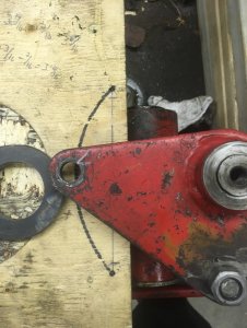
Lets start with the "triangle plate". As stated incorrectly earlier, the OEM stroke of the steering main rod is 5". The hydraulic cylinder from JD I have has a stroke of 4.5". I went with multiple ways to calculate and verify the new location for the hole on the cylinder side. One of them was using plain trial and error and the other one with math.

I must say I wasted a lot of time with trial and errors when math do give the answer right away. The things to know is the 5" travel of the main rod (the arc in a circle) and the original radius for the hole of the steering arm is 3.75". Using The Complete Circular Arc Calculator and entering:
Radius of Arc : 3.75"
Width of Arc : 5"
You can get the angle of the arc which is 83.62063°

Now using the exact same tool again I entered
Width of Arc : 4.5"
Angle Subtended by Arc : 83.62063
And we get the Radius of Arc needed which is 3.375" or 3-3/8"
IMG_9419.jpg

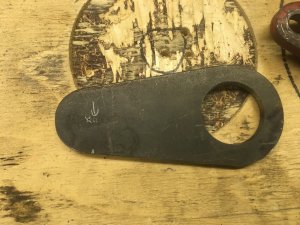
With this I was able to build the arms that will link to the cylinder out of 1/4" thick plate
IMG_9421.jpg

Then I copied the arm for the tie rod with 3/8" thick plate, here it's not yet fully shaped as at that moment I didn't know if one of the 2 sides of the cylinder arm would be welded directly to this plate on the same plane.
IMG_9422.jpg

Then I figured a way to align the new arms with the original angle. If any one wonders, the angle between the 2 holes originally is 87°. Oh also at first I was planning on installing the cylinder as close to the axle as possible, this is why there are some shims in this picture but I reverted this later. I also found out that respecting the original 87° angle didn't work, the cylinder's arm on this pivot was interfering with the tractor frame. I ended opening this angle probably closer to 95° at least. Changing this doesn't matter as the main tie-rod's length can be adjusted to compensate for this. Note: the 87-95° angles here is the angle formed by the center of the 2 holes on the "triangle" in relation with the center of rotation. The 83.62063° stated earlier with the math is the angle of movement of the plate on its axis. Not to be confused (:
IMG_9435.jpgIMG_9436.jpg

Then I was finally able to figure how long I had to remove from the cylinder's shaft: about 3-1/8". The blue mark bellow is where I wanted the hole's center to be, not where to cut, this is why it seems to be 2-1/8" but I did cut out about 3-1/8".
IMG_9438.jpgIMG_9439.jpgIMG_9440.jpg

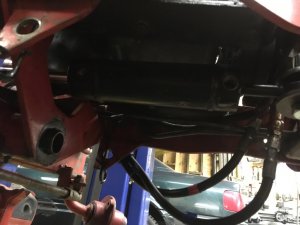
Here is the cylinder, barely visible (sorry), under the engine. There is at least 1" of clearance everywhere and the cylinder is totally inline with the frame (and where the original rod was)
IMG_9448.jpg

Oh and also I added a support between the cylinder mounting frame and the mid-lift cylinder bracket to add rigidity and not rely only on 4 bolts.
IMG_9450.jpg
 
Last edited:
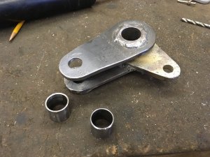
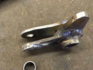
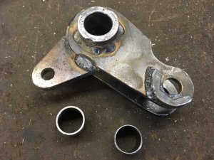
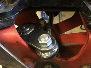
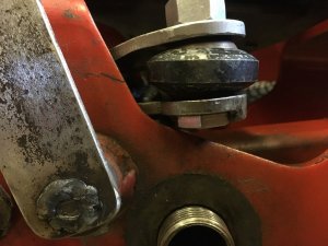
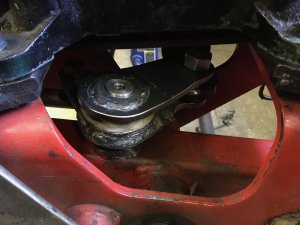
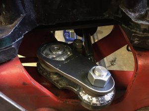
Fast forward a bit, here is the completed relay bracket (triangle plate). Oh also a friend turned me hardened steel bushings. The original bushing were not brass I think and since it's greased I preferred to used hard bushings to prevent wear. Obviously I'll have to keep proper lubrication otherwise the hardened bushing and the hardened shaft on the axle will wear each other.
IMG_9461.jpgIMG_9462.jpgIMG_9463.jpg

And here are more pictures of the cylinder frame.
IMG_9464.jpgIMG_9465.jpg

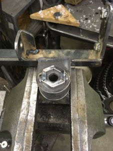
Went beyond what was needed and I made a hex "socket" to prevent the bolt (or nut?) from rotating while assembling the cylinder as this will be hard to access. I could have welded one or two flatbars I know... I wanted to try this. Oh btw what is a hole sawn with a jigsaw to try to reach a hex? A torx hole!
IMG_9477.jpgIMG_9478.jpgIMG_9479.jpg

Here is the kit without the anti-rotation locks for bolts/nuts.
IMG_9472.jpg
 
Tiny semi-related update to this project, since my tie-rod ends are worn and I had ordered tie-rod ends for my 4ws trailer I ordered tie-rod ends to make an upgrade for the 1655. I feel this upgrade won't be too much when the hydraulic steering will be operational.

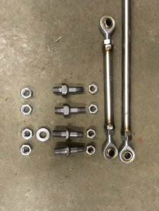
The tie-rod ends are 12mm sized import ones, LH thread at one end and RH thread the other end and I also ordered matching 12mm SS nuts, one for a jam nut and the other one to weld on a tube. I had the luck of finding SS 3/8 pipe in my stuff which was long enough to make the tie-rods! I thought I had pictures of the completed tie-rods but seems I only have them in the first picture with the adapters.

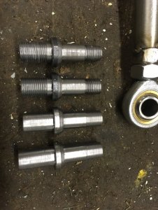
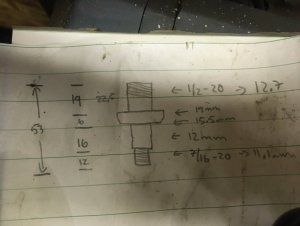
Since the tie-rods are metric (wayyyyyy less expensive than imperial ones, seems the imperial one are made to order specifically for the US market) therefore I had to find a way to install them on the arms with 1/2" holes (12.7mm). I thought about making sleeves and using 3/8" bolts or something like this but it was one of 2 possibilities, too thin walls for the sleeve or too small bolt for the application. In the end I chose to build adapters that would get bolted on the arms at one end and would receive the 12mm tie-rod ends at the other end. I kept the original 1/2"-20 thread and at the other end I went with 7/16"-20. The adapters include the spacers required to allow the tie-rod ends to rotate on their ball.

I know 2 of them are looking way nicer, the threaded ones are made out of scraps while the unthreaded ones are from a cold roll bar. The remaining threading is to come as I can't do those threads myself my lathe has a metric lead screw (and I do not have the change gears) and with a die I never really was able to thread anything above ~3/8" diameter.

IMG_0040.jpg

Here are the specs, keep in mind for whatever reason I draw them upside down! On the left are the lengths in millimeters and the right is for the diameters. BTW the 19mm long end you need 3 like them and one with 22.5mm long to install on the main pivot arm over the front-axle, this one is 3/8" thick instead of the 1/4" thick arms on both sides. It's also why the "bottom" one in the picture above is longer.

IMG_0041.jpg

Once I have the 2 other adapters threaded I'll be able to test this, I think I'll get rid of a lot of play in my steering and hopefully this style of tie-rod ends will prove of heavier duty.

What do you guys think?

Oh also, the hydraulic steering was on hold partly since I didn't have enough 3/8" tube... Well I ordered and received 100' of 3/8" hydraulic tube, I think this should be way enough for all my future needs... Why 100'? ~2$ CAN per foot at a metal supplier with a minimum of 100' (5x 20') instead of 8$+ per foot from a hydraulic supplier and I plan on getting to 6 hydraulic circuits on the 1655 which requires a lot of tube.
 
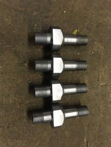
It works! I had to make the adapters again from scratch this time from 1" OD cold roll stock instead of 3/4" OD hot roll, I realized when installing the tie-rod connecting both wheels that the tie-rod was touching the huge front axle nut! I made the adapters from 1" stock to have a wider contact with the steering arms and also increased the length by 1/8" to clear the axle nut.

We even over-engineered the parts and made flats to be able of holding them (without a vice-grip that is) for installation! The flats are 13/16" and were so easy to make with a square collet block on the milling machine, one setup and repeat 8 times the exact same operation!

IMG_0123.jpg

Again I found out an error when I went to assemble the small tie-rod, it's adapter wasn't clearing the front axle pivot! Prototyping when you are a bit lazy (;

I shrunk down the spacer as for the small tie-rod I didn't really need to move the tie-rod to clear anything and this allowed me to make it shorter and it fits perfectly now! I also shortened the corresponding adapter for the right wheel as to keep the tie-rod on the same "plane" as the original one... if it matters.

IMG_0142.jpg

Oh and somewhere I confused something and I ended making the 1/2"-20 side too short... Well I'll leave it this way I don't think it will matter and I don't want to annoy my friend again to make the threads.

IMG_0143.jpgIMG_0145.jpgIMG_0146.jpg

This modification removed a lot of slop and so far it feels sturdier but there is still some play the "master" rod from the steering box but this one will be replaced by the hydraulic cylinder.
 
This project is now well underway to be completed hopefully today!
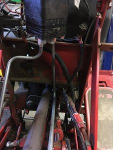
The first step I took was to adjust the tube returning the oil from the spool valves back to the transmission. I made it in a way that I can use the tube with or without the hydraulic steering, I simply have to replace the tee with an elbow and the tube fits right in place. I did this specially since I didn't know if I would be able to complete the project and I need my tractor to be easy to re-assemble. Then I also bent the tube from the steering column back to the transmission in the same tee. This tube might be re-created as to route it differently and leave more space clear under the steering column where I plan to eventually install 1 or 2 divider valves to have more accessory circuits.

IMG_0216.jpgIMG_0219.jpgIMG_0221.jpgIMG_0222.jpg

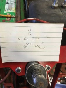
BTW if anyone wonders here is how the column is oriented. Chose this orientation as the LT and RT are closest to the steering cylinder, OUT port is on the correct side back to the transmission return port (left of the tractor) and the IN and AUX are also on the correct side from the transmission and back to the spools! BTW if anyone wonders, RT is the port where the oil exits when the steering is turned right (RT = Right Turn?). This means in my case that RT port goes to the blind end of the cylinder as to extend it.

IMG_0220.jpg

At that point the project was going well I decided to use my hydraulic power pack to actually try the steering column that I previously rebuilt. I initially attached it when the column was on the tractor but I didn't manage to get the column to work and removed everything to work on my bench instead... Forgot to remove the mower from the tractor before disassembling it and I regret it, it's sooo much in my way when working.
IMG_0226.jpg

I don't know why but the steering valve didn't work. I mean not at all. The oil was flowing properly from IN -> AUX but barely any oil came back in OUT and the cylinder never moved. I tried with and without the pump running at various moments. At one point I even removed the cylinder and I barely had any oil in only one of the RT/LT (don't remember which) port. I was so afraid I made a mistake while rebuilding the valve but on the other hand I really took my time and followed every procedure. When I turned the steering I had pulsating sounds and a bit of pressure/vacuum on only one of the RT/LT ports. I didn't and still don't think I understand what was happening. I decided to fill both hoses of RT and LT ports and keep the hoses up as to force the oil up. At moments I had oil bubbles in one hose so I kept filling it up and playing around with everything. I kept doing this for a long time probably 30 to 45 or may be even 60 minutes. I was so discouraged I lost notion of time.

At least it never leaked!

Then at one point the steering got really hard, nearly blocked... Forced it a bit (turns out it wasn't that hard) and out of nowhere it instantly started working!! I guess something was stuck inside. I played with it quite a lot, with and without the pump running and everything kept working perfectly! I can tell you I was relieved.
I didn't test if the cylinder was actually easier to actuate with the pump running BUT the pump's sound changed when I turned the steering, I guess because of the assistance it was providing and the different oil flow.

Then I made a mess of disconnecting all of this (;

Oh and if any 1655 owner wonders about this modification something isn't easy to guess: the hydraulic steering from the JD 318/322/332/420/430 (or may be at least the 5 ports version... there are more than one model of steering columns through the years) is actually MORE turns lock-to-lock than the original 1655 manual steering box. Something close to one full turn more! May be something to think while designing the pivot arm on the front axle. I hope I won't have to but worst case since I designed it to use full stroke of the cylinder I might re-make it one day as to cut back on steering turns, I'll see how it feels this winter. I would have hoped/expected the oposite, like old cars that had less turns when equiped with power steering (at least for VW and Honda)
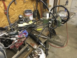
 
Then I moved to the cylinder. I had custom hoses built to my specifications, I tried to keep them long enough for slack with the small movement of the cylinder and keep their ends at a convenient place. I preferred a segment of tube from the steering column again to keep as much room clear and it's easier to keep a tube in place than a hose.

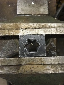
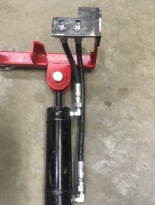
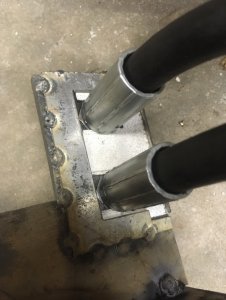
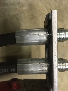
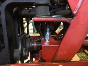
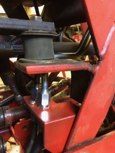
I created a probably over-engineered bracket to hold the hoses where they meet the tubes, I hate cutting internal hex holes but it was the best way I could find. This is where I am at currently, paint was applied yesterday and today I'll hopefully create the 2 remaining tubes.

Oh and yes the box was used as a gauge for the spacing required between the cylinder bracket and the additional hoses bracket :)

IMG_0228.jpgIMG_0236.jpgIMG_0237.jpg

I created a locking mechanism for the hoses inspired by the brake hoses on my VWs that are often held with such U clips on specific brackets. There happens to be a bit of space in the fitting. The only addition I will make is a hole through the bracket and the U-U clip to prevent the clip from moving with the vibrations.
IMG_0238.jpgIMG_0240.jpgIMG_0241.jpg

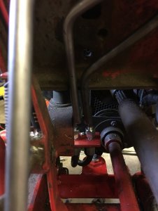
And here where are the hose ends, right under the rear left engine mount. They are on the right side as to not need to cross the 2 tubes from the column!
IMG_0242.jpg
 
Here are the last 2 tubes from the column to the bracket where the cylinder hoses are held in place
IMG_0244.jpgIMG_0245.jpgIMG_0246.jpgIMG_0247.jpg

Of course for the last flare of the last tube I realized after flaring that I didn't install the 2 fittings for this end... I tried cutting it right at the flare base and re-bending it differently but it was definitely too short so I had to re-make it completely! I guess I'm not the only one making this mistake (:

Anyway, now it is fully working! The steering is really easy to turn even with one hand and without even grabbing it but it is wayyyy slower than the original steering box (too many turns). Also I made a mistake somewhere and now I can't turn the wheel to the stops on the axle therefore I am missing a couple of degrees and if the inner wheel blocks full lock it will transmit more force in the steering linkages. For now I'll see if I really dislike the new ratio and if required later on I can re-make the pivot arm on the front axle to change the ratio, I can even probably ignore a part of the cylinder's stroke if I want to make it way faster (I probably would have to make a stop on the cylinder to avoid excessive force on the linkages by the cylinder). Time will tell, at least now this winter I should be able to steer the tractor while the snowblower is off the ground without having to move the tractor which should free my right hand to always be on the spool valve levers (:

Other small notes about my project.

First the steering column bracket is really close to the amp meter, in fact I unscrewed the dashboard, it moved a bit and shorted the amp meter to the steering column bracket... If someone does copy my concept, think about not having the "horizontal" part at the top of the tractor's A-frame, it should be at least 1/2" - 13mm lower to give clearance. I installed 1/8" - 3mm thick rubber all the way around the bracket to try to reduce this risk. At least there is a breaker on the tractor.

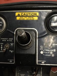
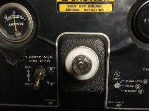
Second current I cannot screw the ignition switch completely, it is so close to the steering column's main body that it isn't straight... At least it can be in the original hole. Don't know what I will do on this, I don't want to modify the dashboard! Any suggestion? Anyone knows if there are ignition switches compatible that are smaller in diameter?

Third I had to get the hour meter wires longer by about 3" - 7cm otherwise they would never reach. Also had to bend the terminals on the meter as, like the hour meter, they were too close to my column's bracket.
 
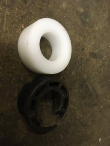
Not totally related nor unrelated, I had quite a lot of play in the steering and it was annoying. The plastic bushing at the top of the column was worn in an oval shape, like if someone had pulled or pushed on the steering while driving the previous tractor for hours. I simply drilled out the old bushing and made a new one our of POM (delrin/acetal)... well in fact I made 3... the 2 first ones were wayyyy too tight and the steering was hard to turn! I'm the expert of too tight tolerances (:

I thought about making it out of brass but out of mostly laziness I tried POM, I'll see how long it lasts and it's quite easy to make new ones. Oh also... if you want to replace the bushing without tearing the whole unit appart you are mostly stuck with drilling it out from the top, the studs that hold the hydraulic components together prevent you from removing the column tube therefore pushing the bushing from the back is not really an option. Maybe something like a 3/4" ID 7/8" OD brass bushing in a tight plastic bushing would be the alternative, drill out the plastic and the brass would be free to slide off if replacement is even needed... I don't know if this would provide a longer life anyway.

If anyone wants to copy it, here are my final dimensions. I made the part metric (the steering column seems all metric except for the bolts)
OD : 36.05mm (slight press fit in the column)
ID : 19.30mm (my first ones were 19.10mm then 19.20mm, both too tight)
Length : 13mm
You can make the length whatever you want, I just rounded it to 13mm for no specific reason but it is longer than the original bushing.

IMG_0265.jpgIMG_0266.jpgIMG_0267.jpg

No more slack!
 
Mac if you want faster steering change the steering cylinder to a smaller diameter! Those Deere units have WAY too much volume !
The 318s steering sucks in my opinion because of this.
If you increase your oil volume you make a bunch more heat and that is never a good thing. You dod a very nice job on your system for sure!
 
Back
Top