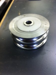
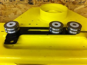
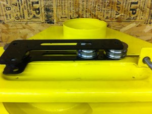
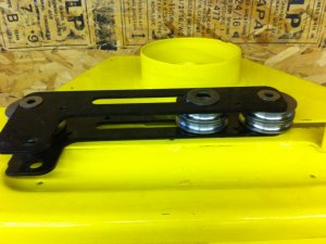
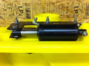
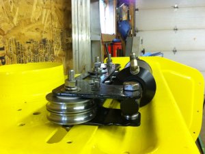
John Deere Quik-Tatch hitch on Massey Ferguson 1655

MacWorld

Tractorologist
Member
This thread will begin by the exact same content as I uploaded on GTTalk and then will continue with the project. If GTTalk is still online when you read this (hey we don't know where this boat is going!) you can search for the exact same title if you want to see the posts of other members and discussions. I will only copy my posts which contain information on my build process, no offence to anyone who commented in the topic, it's always appreciated but I don't want to copy other's posts.

Bonus for TractorFanatics, I re-generated all pictures with bigger size, it seems I was not coherent before and exported with multiple sizes!
 
2018-02-07 1/2
The quick hitch I bought was from a 4xx tractor. I don't know yet if from the 420/430 era or from the later 455 and such. I don't think it matters a lot as I did not use the part that attaches directly to the tractor.

You may think my design is overkill... This is quite probable as I hate doing things twice and being a software engineer I never know when something I build is strong enough.

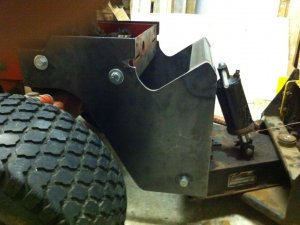
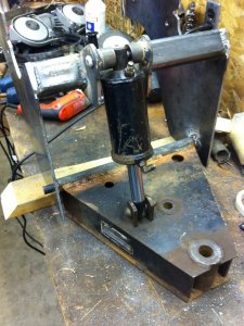
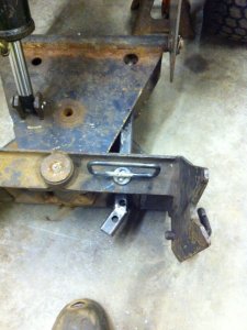
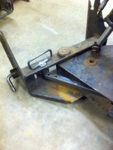
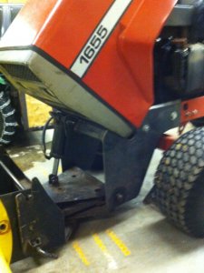
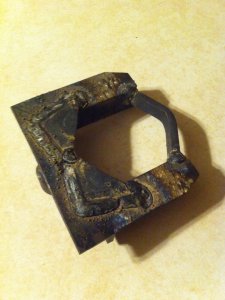
Here you can see the rough version of the hitch. I think the pivot used to be fixed to the horizontal part, I drilled it all the way from both sides and used 3/4" rod to replace it.

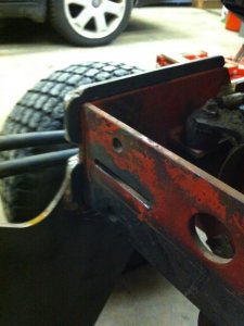
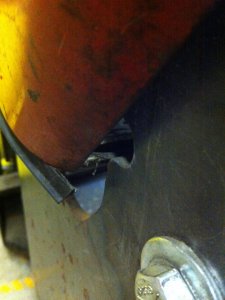
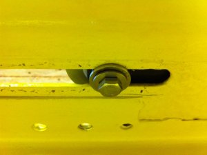
There are 2 cuts, on both sides that are optimized to get the implements as close to the tractor as possible without altering the tractor. First you see the cylinder is about 4-6" in front of the tractor. This is to allow the hood to open without touching the hitch at all. Also you can see 2 small round cuts a bit left to the frontmost bolt, this is also to clear the hood when it's opening as it is pretty close to the tractor's frame.
IMG_4822.jpg

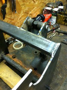
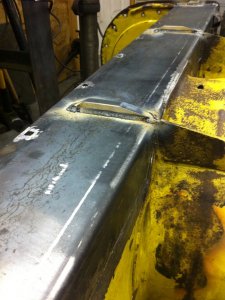
I welded 1/4x1/2 flatbars on the hitch at top, bottom and front of the frame on both side, the bolts are only used to keep the hitch from "opening". The hitch slides on the frame from the front and is then bolted.
IMG_7305.jpg

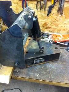
Here is the hydraulic cylinder bracket fully welded in place. When it's at it's lowest possible position, the tractor lifts it's front end a bit off the ground, this was made to allow the implement to follow the ground on "down going" slopes. It's also helping when scraping ice!
IMG_4827.jpgIMG_4828.jpg

I know, the round spacers for the top mount of the cylinder are overkill, I used what I had laying around!
IMG_4829.jpg

Currently I do not have installed the 3rd spool valve therefore I cannot install the angle cylinder. I made a temporary part to allow me 3 positions for the blade from straight to about 30°. I also made the hitch pin myself as I did not know at the time that they were available this size!
IMG_6069.jpgIMG_6071.jpg
 
2018-02-07 2/2
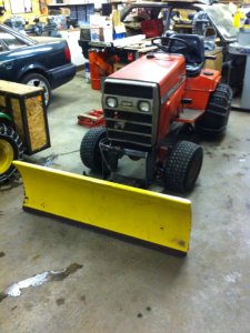
Here is the blade on the tractor as it is sitting tonight. BTW you can see my counterweight installed on the JD 214, it's 3/4 full of concrete bricks! It is made for the cat 0 3pt hitch.
IMG_7300.jpg

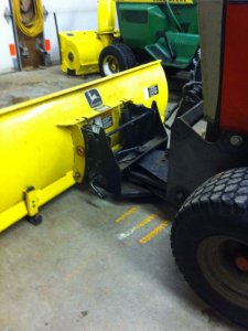
Here you can see the blade that gets a bit far from the tractor. I did not have much choice to be able to open the hood.
IMG_7301.jpg

The hood open, it is not touching the hitch at all and it can be removed. I had to straighten the 2 hooks/hinges that go in the slots at front of the frame but not a lot.
IMG_7302.jpg

Here is why the small cut, sometimes the hood gets closer than this as sometimes it hinges closer/further from the frame
IMG_7303.jpg

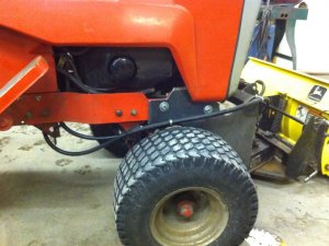
And my current hydraulic setup hooked instead of the mid lift. You can also see I followed the shape of the frame where the starter's positive wire is connected.
IMG_7306.jpg

That's where I am so far. The restauration of the 47" snowblower is nearly at the point where I can paint it, I will have to find o-rings to add the 3rd spool valve and then I'll have to modify the PTO shaft as it is too short, it will be lengthened and there is a small modification I will need to make as currently it is not hooking (the balls that keep it on the shaft of the tractor). Lastly, I will make a custom pulley hub with 1" 15t inner splines (bought a union with the splines) to install 2 larger pulleys to slow down the front PTO to JD's speeds. The 1655 is 1:1 with the engine but it's slower on the JD's and I do not want to overspeed the snowblower nor be on too low RPMs and lack power.
 
2018-02-12
Last week I went to the New Holland dealer where I take my Massey Ferguson parts (the parts department director used to work at Massey Ferguson back in the days when the 1655 were selling new!) and I got all the seals for around 20$ (Canadian pesos)!

New information, I'll soon be starting to make the parts required to get the right PTO speed. The 1655 has a 1:1 ratio therefore 3600 PTO RPM for 3600 engine RPM. Looking through John Deere documentation I found the impeller on 47" and 54" snowblowers must run at maximum 950RPM. There is a chain reduction on the snowblower, 19T gear (input shaft) to 40T gear (impeller shaft) therefore the tractor's PTO must run at 2000RPM. This information was hard to confirm since there are many different sources of information on the Internet and the old non-quick-hitch 47" were different, I think. To achieve 2000RPM on the front PTO I will make a hub to install pulleys at the shaft under the tractor. The clutch is about 5.5" in diameter therefore I will use 10" pulleys and should get proper RPM. The pulleys will be bolted to the hub therefore if I make a mistake I will easily be able to swap for other diameters.

I'll post pictures when this gets started. So far I have a 1" 15T shaft coupler on which I will weld a flange (about 3" diameter) to bolt the pulley on it.
 
2018-02-13
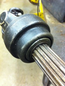
Yesterday between 2 coats of POR15 on the impeller, auger and blade I tried the John Deere shaft on the front PTO. Sadly the PTO shaft is too short on the 1655 to allow the female shaft to lock, it's missing around 4mm (3/16") between the "lock groove" and the circlip in front of the pulley. If I remove the snap ring and the following washer, the PTO shaft locks properly. Sadly cannot modify the John Deere shaft to shorten it as it would remove required parts for the locking mechanism.

Given I will make a custom pulley hub, I will make it a bit shorter and machine a new groove for the snap ring in the shaft of the 1655. At the same time I plan on replacing all bearings/seals for the PTO, the front axles and the wheels, removing the front axle doesn't seem something too fun!
 
2018-02-15
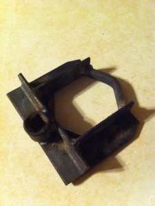
I had to make a tool to remove the front PTO shaft from the axle as I will have to machine a groove in it. The nuts are 2.5", I could not think buying a tool and I was not going to use a pipe wrench on those! Ugly tool made using what I had laying around but it got the job done. My first try was when the tool was more like an open wrench, only the angles without the reinforcing triangles and the closing bent bar but that was not solid enough. I used a 2' breaker bar on which I was standing to break free the rear nut!
IMG_7315.jpgIMG_7316.jpg

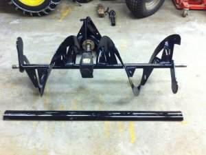
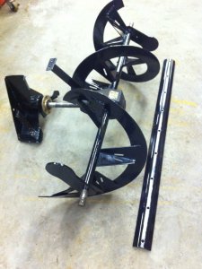
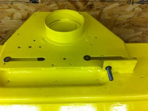
And here are the painted parts so far (POR15). The housing will be repainted Jaune Deere (jaune is French for yellow). The blade is new, I had it copied from the worn out original at a fraction of the cost and the augers were repaired as they were abused
IMG_7310.jpgIMG_7312.jpg
 
2018-02-18
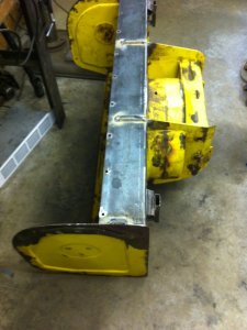
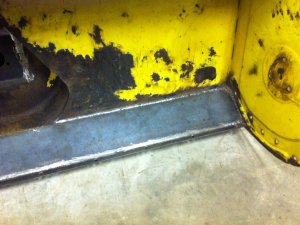
Less informative post tonight to show the current status of the snowblower housing. The bottom was replaced completely and I reinforced it because originally the inner and outer parts that I replaced were not welded together, they were on top of each other and the blade's screws kept them together. This is a heavy rusting spot therefore I chose not to replicate this and I added reinforcements to prevent the blade from bending to easily the housing.
IMG_7317.jpgIMG_7318.jpgIMG_7321.jpg

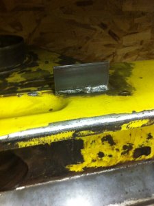
This part was cut off by the previous owner who replaced the original rotation mechanism therefore I had to weld new metal which I will drill a hole into and cut to the proper size once I will get all the parts for the mechanism and I can find where the hole goes.
IMG_7320.jpg

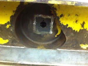
The center of the turbine housing was rusted and butchered by the previous owner so I replaced it also
IMG_7322.jpg
 
2018-03-01
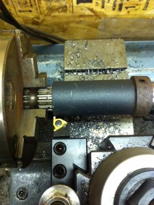
Here is a small update of last week's progress, I modified the front PTO shaft to add the snap ring groove

Here is the cheap way I used to locate the new groove. Lock the female PTO shaft on the male, add a spacer then lock it in place with a collar. Make sure you can remove and install the female PTO without problems. Get the shaft with the spacer and the locking collar in the lathe chuck, align your grooving tool (1.6mm IIRC) so it will cut pretty close to the end of the space, remove the locking collar and the spacer, install a live center then you are all set! This does not requires a super high precision since the pulley hub will be made to size later
IMG_7339.jpg

Here is the female shaft mated to the male with the snap ring in the new groove
IMG_7341.jpg

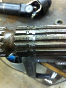
As you can see the groove is not too far from the original one, in fact it seems moved the thickness of the groove (1.6mm)!
IMG_7344.jpg

Now that I bought top quality bearings and destroyed them upon first install, I will have to figure out the order (that I didn't take consideration of while disassembling) of the spacers for the shaft and I'll have to install new(er?) bearings and this should be ready for the new pulley hub.
 
2018-03-16
Ok, the snowblower will probably not be useful for this winter ): I think I am listening too much to ThisOldTony, Joe Pieczynski and Stefan Gotteswinter videos!

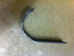
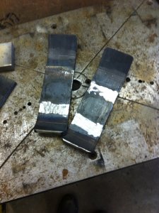
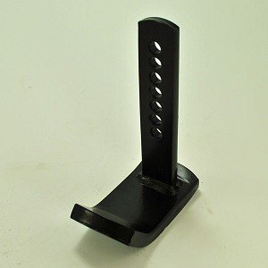
Anyway, here is a part (well 2) I needed to make. Previous owner ate them and replaced them by silly parts he welded to the snowblower... I did not agree with that
thumbnail.jpg

To make this recipe you will need
- 12" of 1.25" x 0.375" flatbar
- 9.5" of 2" x 0.25" flatbar
- 2x 0.125" drill bits (you will break one and strugle to remove it from the hole)
- 0.375" drill bit (this one is still no match for the Delta DP600 but you won't break it)
- a drill press
- a welder
- a Markal silver-streak (this is the magic pen to write on metal, even oily or greasy!)
- a bandsaw
- a 20T press
- scrap metal to use as cheap bending die since you never have the time to build a copy of Swag Offroad's bending press

Consider that I am using .25" stock on the ground since I did not want to try killing myself with flying metal bending something thicker. Safety first!

First after looking after every single pictures of this part on Google and not finding much dimensions, you will draw this on your stock
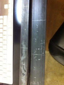
IMG_7368.jpgIMG_7369.jpg
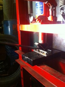
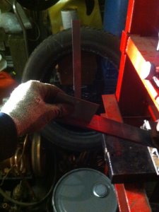
Since you don't have proper bending tools, you will set both short ends in the center and make the bends BEFORE cutting the 2 parts appart. This will make up for the too wide bottom die you made.

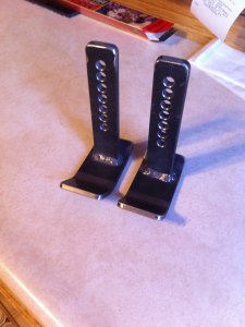
Then you will enjoy making your parts forgetting to take pictures of the process and will come up with that
IMG_7370.jpgIMG_7371.jpgIMG_7372.jpg

Quick informations making up for missing pictures
To make the hole equally unevenly spaced on both parts, weld them together and drill them both at the same time. Drilling 7 deep holes is faster and more "ISO-ish" than 14 shorter holes. Those holes are for adjusting the height. I need only one (my driveway is pretty flat) but I like breaking drill bits therefore I made all of them.
The holes are spaced 0.5" apart and on the female part (the snowblower) there are 2 holes 0.75" apart. This will give you adjustment by 0.25" increments. I plan on adding a 3rd hole on the female part 0.875" from one of the 2 others to upgrade to 0.125" increments. Do I really need this? I don't know but I prefer drilling before painting the whole thing.

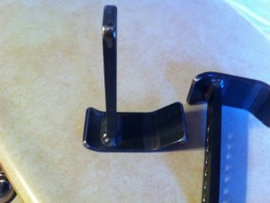
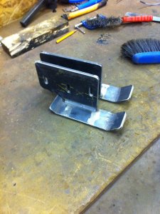
Those are the shoes for behind the snowblower to prevent it from digging while going backward mostly. The longer side go backward.

Next step will be to make the front shoes!
 
2018-03-18
To what I found there are at least those models of Quik-Tatch, this list comes from the compatibility charts of the 2 versions of the 47" snowblower (M01471X and M047SBX)

BM18121 : 318, 322, 332
BM18122 : 420, 430
BM17347 : 445, 455
BM18120 : F900 Series
LVB24898 : 4010, 4100, 4110, 4115
BM19782 : X465-X595, X700 Series
BM20921 : 2210

The tractors that were listed for the older M01471X are also listed with the same Quik-Tatch in the list for M047SBX.

Yes I found out about the grapple in this thread : http://gardentractor...ch-accessories/

I am thinking about making one myself eventually!
 
2018-03-28 1/2
Update on my slow progress, I made my front shoes and took the time to document a bit more the process as the part on the ground is made the same way as for the rear shoes... same way... well not completely... more on that

Here is my cheap bending dies
IMG_7373.jpg

And how I approximate my angle while bending, I wanted 45° therefore I set my protractor at roughly 22.5° and eye balled when to stop (until the protractor bar gets vertical)
IMG_7375.jpg

This is both shoes bent before cutting them appart. This is required because my lower die was too wide!
IMG_7376.jpg

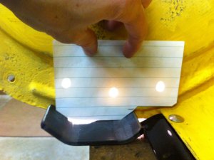
Then I proceeded with the vertical part of the shoe using paper to guess the required shape. I tried maximizing the area of contact with the "raised" parts of the snowblower walls as they are thinner than new since they were rusted quite a bit.
IMG_7377.jpg

This is how I guessed where to drill the holes and how to center the part with the holes
IMG_7378.jpg

Now... I mentioned that they are similar to the rear shoes? Well since I wanted to put pictures here that I forgot to take for the rear shoes, I rushed and copied my previous shoes and I was left with about 3-4" of stock. Well the front shoes must be longer... of how much? About 1.5-2".. My leftover!!! I had to cut both my shoes and extend them by half my leftover. This is REALLY useless work!
IMG_7379.jpg

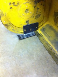
Here is the final shoes
IMG_7399.jpgIMG_7401.jpg

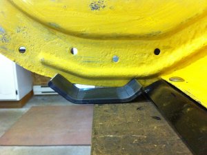
And how they fit
IMG_7403.jpg

Remember that I have pretty flat asphalt driveway. I don't need to install the shoes outside therefore I did not drill the holes to raise the snowblower.
 
2018-03-28 2/2
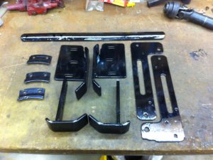
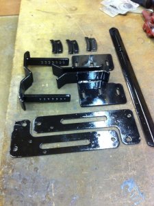
Later on I proceeded and painted my new shoes and other parts that were in need with 2 coats of POR15. BTW if you don't know that: if you use POR15 on sanded/new parts, make sure to prepare them with the Metal Prep, it really helps the bonding of the POR15!
Attached Thumbnails
IMG_7415.jpgIMG_7416.jpg
 
2018-05-01
Non exciting progress update, the shell is primed and I started painting it in the original Jaune Deere paint. Damn there are a lot of surface area and hard to reach spots to cover it's painfully slow to do!

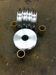
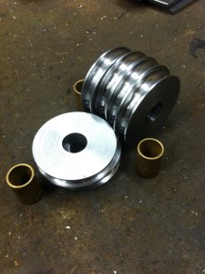
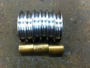
Also I've been working with a friend who has a CNC lathe, we made a CAM model for the required 6 cable pulleys for the ~270° chute rotation modification. Sadly I can't find appropriate pulleys at a reasonable price here therefore we will turn them from 2.5" steel round stock with brass bushings. I will post pictures of those when they start taking shape. We will also turn a custom hub for the PTO speed reduction pulley (to replace the lower pulley) with 4 bolts holes to install the ~10 inch pulleys. The pulley are so big they could not be installed if welded together, I will have to slide one pulley in place, slide the 1" 15T splined hub, slide the second pulley and then screw all of this together with 4 bolts.
 
2018-05-02
Today I "fabricated" 2 parts for my snowblower, you might consider me excessive but there is a sealed volume on those blowers and they mostly rust from there, it's the triangle all across the width at the bottom of the snowblower where the horizontal bottom meets the angled plate under the auger. I want to shoot anti-rust in there and seal it.

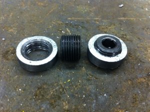
I bought 2x 3/8" taper plugs and 2x 3/8" -> 1/4" reducers (they were out of 3/8 unions). I tapped (can I say that?) the threads until I was able to screw the plugs flush with the outside then I turned and cut the reducers to make bushings that I will be able to weld to each side of the snowblower. While turning I also made sure to remove all the galvanize as it's a health risk when it vaporize from welding near it.

IMG_7487.jpg

I will have to make 2 holes and weld the bushings in place and this will be solved, I'll be able to shoot car antirust and seal my plugs in place.
 
2018-05-12
Progress has been made! The plugs are fully welded in place and the paint is applied to the whole main housing! I don't have pictures of the paint, at this stage I find it pointless but it will be included when the assembly begins.

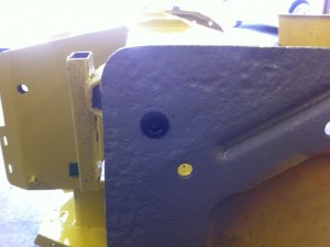
Here are the plugs welded
IMG_7491.jpg

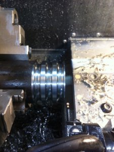
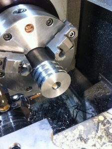
Also today we produced the 6 pulleys for the chute rotation mod!
IMG_7501.jpgIMG_7502.jpg
IMG_7503.jpgIMG_7504.jpgIMG_7505.jpg

My next step will be to cut the bronze bushings to proper length and make a "hub" that will be between the bolt and the bronze bushings and some delrin spacers to fit on each side of each pulley. At least those parts I can make them with my small lathe. The PTO pulley hub is also on the list but it needs CNC features therefore I must wait for my friend on this.
 
2018-05-21 1/4
Great progress has been made, a lot of new parts! I will be specifying some metric and some imperial measurements depending on if it was a bought part (imperial) or machined (metric part) and a list converted value to help. I definitely prefer metric but there is so much imperial stuff around, it's hard to avoid. i.e. the bronze bushing I used where dirt cheap but only available in imperial therefore I chose 3/4" OD and 5/8" ID. Most of the parts are made out of stainless, in fact I used 5/8" stainless bolts I had laying around. Can't beat free material!
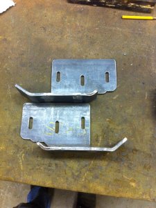
Here are most (I hope all) the converted (approximations) values
1mm ≈ 3/64"
2mm ≈ 3/32"
2.5mm ≈7/64"
3/16" ≈ 5mm
3/8" ≈ 10mm
1/2" ≈ 12.7mm
5/8" ≈ 16mm
3/4" ≈ 19mm
1" ≈ 25.4mm
1.125" ≈ 28.6mm
45mm ≈ 1.75"

For some parts (marked with an *) I machined the bolt's hex head down to a random diameter then a specific thickness, this allowed me to avoid some washers.

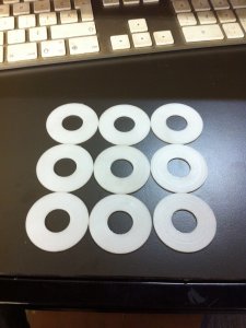
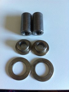
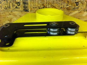
First I machined 1mm thick spacers, 9 of them, 1.5" OD, 5/8" ID that will be installed between the pulleys, they are made out of Polyoxymethylene also know as Acetal or Delrin
IMG_7506.jpg

- The shafts for the 2 outer stack of pulleys. 5/8" OD 3/8" ID and 1mm thick
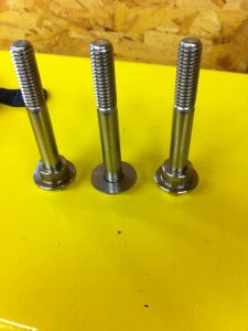
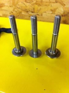
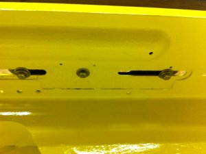
- The "flanged spacers" that ride in the slots of the housing, those could be only a spacer and a washer but I preferred machining a single part. They consider the thickness of the housing, the big washer (next part) and extra space. The big OD was the bolt head * and 2mm thick, the small OD is 5/8" and 7.2mm thick and the ID is 3/8"
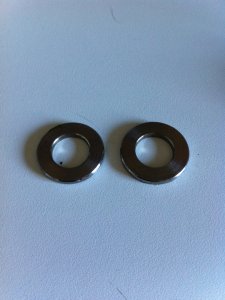
- The washers are standard stainless 5/8" washers turned down to 1.125" OD to match the slot inside the housing
IMG_7543.jpg

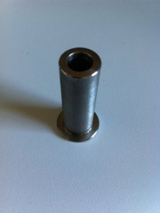
- The shaft for the center stack of pulleys, big OD was the bolt head * and 2mm thick, small OD is 5/8" and 45mm long with an ID of 3/8"
IMG_7544.jpg

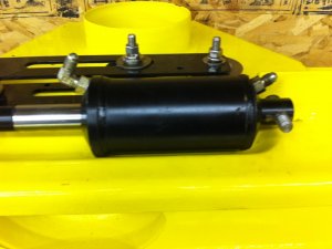
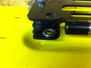
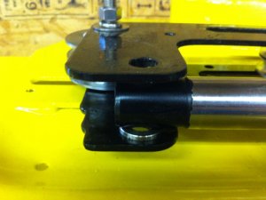
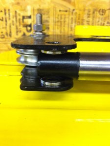
- The spacers for the hydraulic cylinder's shaft that sits between the 2 OEM "L-shaped" parts. The big OD was the bolt head *, ID 1/2" and it's 2.5mm thick
IMG_7545.jpg

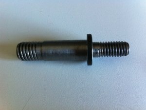
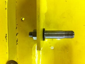
- The "shaft" to install the hydraulic cylinder to the housing. This is the only steel part. This one is probably over complicated but I gave myself a challenge here. Describing from left to right. The first OD is 1/2" with 1/2"-13 threads. 43mm long total, 26mm non-threaded. I know my threads are not great looking, I had to reduce the OD otherwise I was not able to use the thread die and my lathe is metric! Largest OD is 3/4" and 2.7mm thick. Smallest OD is 3/8", 3/16" non-threaded and 17mm with 3/8"-16 threads. The 1/2"-13 nut will be a "castle nut" and a hole will be drilled in the shaft to preventing the nut from backing off. It doesn't need to be precisely installed nor tight to the cylinder as the cylinder should be able to move a bit.
IMG_7546.jpg
 
2018-05-21 2/4
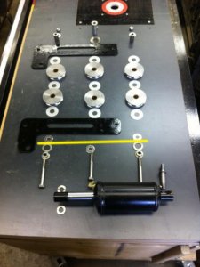
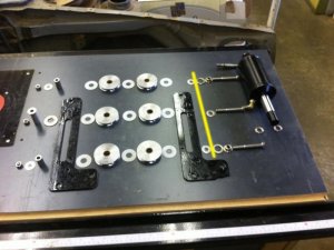
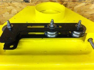
Here are the custom parts and the off the shelf parts displayed how they must be assembled. The stacks do not match directly in the "L-shaped" parts as that would have took too much space therefore it's offset. The housing of the snowblower goes where I draw a yellow line
IMG_7508e.jpgIMG_7510e.jpg

And there is the installation of the parts. This is a dry installation, all parts should be greased but I will do this later as for now it will be collecting dust during the summer.

First, off the shelf 3/8" washers and the cylinder shaft
IMG_7517.jpgIMG_7518.jpg

Now let's build the pulley stacks, the center stack without it's shaft for now
IMG_7519.jpgIMG_7520.jpgIMG_7521.jpgIMG_7522.jpgIMG_7523.jpg
 
2018-05-21 3/4
Install the first L-bracket then the 3 stacks
IMG_7524.jpg

Install the second L-bracket then off the shelf 3/8" washers for the outer stacks and 5/8" for the center
IMG_7525.jpgIMG_7526.jpg

Install the center pulley stack shaft through all parts until it reaches the housing
IMG_7527.jpg

Now here are the stacks that will be pushed up from inside the housing into the pulley shafts. Center bolt only has a off the shelf 3/8" washer
IMG_7532.jpgIMG_7533.jpg

Push the bolts up from inside the housing and install spring washers and nuts.
IMG_7547.jpgIMG_7548.jpgIMG_7534.jpg
 
2018-05-21 4/4
Then install the cylinder base on the shaft
IMG_7535.jpg

Install one of the custom 2.5mm washers
IMG_7536.jpg

Push the complete L-bracket assembly to the right
IMG_7537.jpg

Install the 2nd 2.5mm washer
IMG_7538.jpg

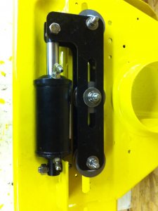
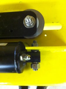
And here is the completed installation
IMG_7539.jpgIMG_7540.jpgIMG_7541.jpgIMG_7542.jpg
 
2018-08-13
New progress has been made!

This weekend my friend with a numeric lathe helped me start with the parts required for the PTO speed reduction. I am currently not able to hold 3.5" round stock on my lathe since I don't have the external jaws (and it's a long discontinued model for which the jaws aren't made...) and I needed a bolt pattern. Since I needed a hole in the part, he drilled it to the final dimension to fit the 1" 15T spline sleeve and I can use this inner diameter to hold the parts

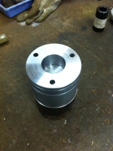
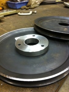
That is the result of what he made. Bolt pattern 3x2.75" and he pre-parted the 2 parts to help guide my horizontal bandsaw. One part-off is less deep since it started vibrating too much and the carbide insert / holder are worth too much, the bandsaw can do the job fine.
IMG_7765.jpgIMG_7767.jpg

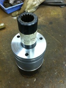
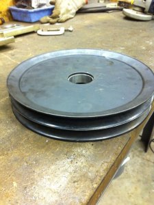
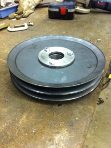
Then I parted them off with my bandsaw and I machined them to final specifications. This one is the thicker one (0.546") will be welded to the spline sleeve and will reside between the 2 pulleys. You can also see that I had to machine one side of each pulley in order to get them closer together. They are "split steel pulleys" and I think they can handle B v-belts.
IMG_7768.jpgIMG_7769.jpg

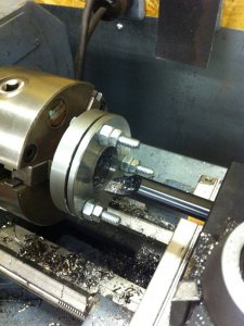
This one is the thin one (0.25"), it will have bolts welded to it to make "studs". In fact it's goal will be to provide non-rotating studs to help assembly. It will be inserted first on the PTO shaft then one pulley will be inserted followed by the splined hub then the second pulley and everything will be bolted together and held on the lower PTO shaft with a snap ring.
IMG_7771.jpg

Of course I forgot to have the thin one drilled bigger than the spline sleeve therefore I had to use my imagination to bore the inner diameter a bit bigger
IMG_7773.jpg

That is where I am now. Next step will be to figure the alignment of the hub to the splined sleeve and weld them together.
 
Back
Top