sickle mower

jdcrawler

Tractorologist
Senior Member
Member
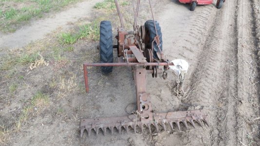
I picked up this sickle mower back while I was still living up in Buckley, Michigan.
I don't know what it was used on. I had thought a Gravely but I don't think so. The drive connection is on the front so that means that it had to have been mounted on the back of a tractor. Gravely attachments are mounted on front and the photos that I've found of their sickle mowers don't look anything like this.

DSCN1218.JPG

DSCN1220.JPG

The drive pulley housing fastenings to the tractor.
The cast iron bracket going out to the sickle bar can rotate up and down from the drive pulley housing.
The sickle bar can also rotate up and down from the end of this bracket.

DSCN1231.JPG


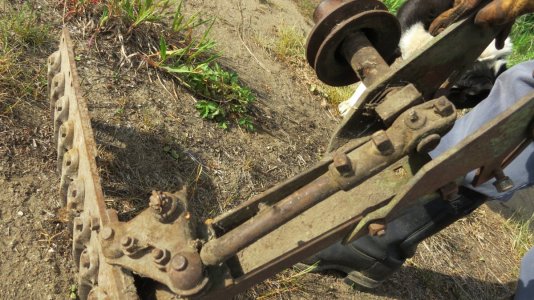
The drive wheel that the pitman arm is attached to has a counterbalance weight on it.

DSCN1222.JPG


There is a notch machined into the pitman arm for clearance for this counterbalance weight.

DSCN1224.JPG


One tooth has the point broken off of it but I have some extra teeth somewhere.

DSCN1228.JPG


Even before I had picked up this sickle bar, I had built up a mid 1960's Sears Custom garden tractor with a sickle mower on it.

2-Blade up.jpg

1C-60's Sears Custom 600.jpg


I ended up selling that tractor.
After I got this sickle bar, I thought of building up another Sears tractor with a sickle bar mower again so I found another Sears Custom garden tractor to put this sickle bar on.

6.JPG


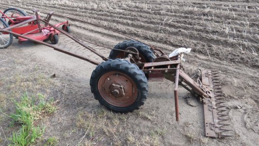
However, I'm thinking of putting this sickle bar on my old 38 Shaw garden tractor instead of re-doing another Sears ?
There certainly looks like there is enough room under it to mount the mower down between the front and rear wheels on this side.

30.JPG
 
Last edited:
When I bought my Sears SS15 it had a sickle bar on it. At the time I had no use for it but I would love to have it now. That’s a nice rig you had with the Sears Custom. This Shaw looks like a good project for the sickle bar.
 
The sickle bar and cutting bare are sandblasted and primed.

DSCN1232.JPG


The two parts are re-assembled.

DSCN1233.JPG

DSCN1235.JPG


The drive housing has been disassembled and soaked in degreaser for about 4 hours and the parts are set out to dry.
Once that are dry, I'll sandblast and prime them.

DSCN1237.JPG


I set one end of the cast mounting bracket in to soak at about 6:00 PM.
I'll go back out just before I go to bed tonight and switch ends.
Then I'll take it out and set it out to dry first thing in the morning and it will be ready to work with after church tomorrow

DSCN1238.JPG
 
That’s coming along nicely as everything you do Ray and it’s fun to follow your projects. What are using as a degreaser. I’ve always used Gunk concentrated that you mix with kerosene but it’s hard to find without paying a lot in shipping. I’ve tried the aerosol cans of Gunk but not happy and too much money wasted on the can and air.
 
Last edited:
That’s coming along nicely as everything you do Ray and it’s fun to follow your projects. What are using as a degreaser. I’ve always used Gunk concentrated that you mix with kerosene but it’s hard to find without paying a lot in shipping. I’ve tried the aerosol cans of Gunk but not happy and too much money wasted on the can and air.

I get Oil Eater concentrent in a gallon jug from TSC. This is a water soluble cleaner and I mix it 50-50 with Dawn Platinum dish soap.
This mixture is then mixed 50-50 with water to make up my degreaser. It does a good job but doesn't work as quick as some petroleum based degreasers. I like it because it is water soluble.
 
Yeah something water soluble is what I’m looking for. Since we’ve been out here in the country it’s too far to drive to get rid of hazardous liquids. I was looking on YouTube yesterday and a lot of guys are using a mixture of Dawn detergent with their favorite degreaser. Thanks!
 
With the engine sitting crosswise on the frame, the flat belt pulley is on the left facing out from the side.

DSCN1244.JPG


Placing the sickle drive parts on the table under the tractor, you can see that the driveshaft is going to be facing forward.

DSCN1245.JPG


The end of the driveshaft had three gear teeth on it that would have connected with matching slots in whatever powered this sickle.
I have machined those teeth off so the face is smooth. Than I drilled and reamed a center hole to accept a 3/8 dowel pin.

DSCN1246.JPG


This dowel pin is the center locator for whatever I have to make to attach this driveshaft to this right angle drive gearbox.

DSCN1251.JPG


This gearbox will fit onto the front of the sickle drive and the other shaft coming out of the gearbox goes over to the other side and will have a flat belt drive pulley mounted onto it.

DSCN1252.JPG


I bought a flat belt pulley off ebay.
It is 7 inch diameter and 2 inch wide.

images.jpg
 
Cool project! Makes me wonder what we did before Dawn dish detergent came on the market....reminds me of that old lady on the Frank's Red Hot commercial, " I use that s!!t on everything".
 

Attachments

  • IMG_2389.JPG
    IMG_2389.JPG
    256.8 KB · Views: 11
  • IMG_2391.JPG
    IMG_2391.JPG
    268.8 KB · Views: 11
  • IMG_2388.JPG
    IMG_2388.JPG
    302.1 KB · Views: 11
Sorry, I pushed the wrong button before I finished the above. My neighbour found the above sickle mower at a yard sale and figured he'd work on it some day. So far "some day" hasn't come around but I found the project interesting so got the "before" pics just in case.
 
The lower pulley and a pillow block bearing are mounted on a 3/4 inch shaft.

DSCN1254.JPG


The pulley is locked to the shaft with two 3/8 square head set screws.
Not only does this keep the pulley from spinning on the shaft but it also keeps it from sliding in or out on the shaft.

DSCN1255.JPG


Using blocks and pieces of strap steel to line everything up.

DSCN1256.JPG

DSCN1257.JPG


Then the hanging bracket is made up to fasten the bearing to the frame.
Once it is all made up, it is primed and mounted back in place.

DSCN1258.JPG

DSCN1259.JPG

DSCN1260.JPG
 
Decided that it might be a good idea to put a angled brace in the center of the mounting bracket for the pulley.
This will help keep it from bending if I should happen to hit something.

DSCN1261.JPG


The right angle gearbox is fastened to the end of the pulley shaft and it is set on blocks to get it lined up.

DSCN1264.JPG

DSCN1265.JPG
 
I need to work on making the belt tensioner next so I'm using 2 inch wide masking tape to represent the position of the belt between the top and bottom pulleys.

DSCN1277.JPG


The belt tensioner pulley is going to be made out of a piece of nylon.
This is chucked up in the lathe.

DSCN1266.JPG


The end is faced off and a counterbore is machined into it.

DSCN1267.JPG


This counterbore is a snug press fit for the bearing.

DSCN1268.JPG


The center is turned down to form a lip on each end.

DSCN1269.JPG


The lever bracket has a piece of 1 inch diameter steel welded to one side of it.
A 1/2 inch hole is drilled and reamed so a grade-8 bolt fits snugly thru it with a nut screwed on the end to tighten it up.
With the bolt going all the way thru, it gives the pulley extra support rather than just having the bolt fasten to 1/4 inch wide bracket.

DSCN1271.JPG


A 1/2 inch shoulder bolt is fit into a hole on the other end of the bracket and welded in place.

DSCN1273.JPG


A hole is drilled and reamed thru a block of aluminum and two bronze bushings are pressed into it for the mounting block for the lever bracket.

DSCN1275.JPG


This is assembled onto the lever.
The mounting block will fasten up to the underside of the frame.

DSCN1276.JPG
 
Do you think you’ll have any trouble with the belt tracking. Your designs and fabrications are educational to watch.

I hope not.
I've never built anything using a flat belt before so this is a learning experience for me.
That's why I'm working on the getting the belt tensioner and the belt itself set up now so I can get everything lined up before I make the mounting brackets for the right angle gearbox on the other side.
 
Got the belt cut down to size today and the tensioner in mounted up under the frame.

DSCN1278.JPG


Pushing the tensioner up to check the fit to the belt.
The mounting block for the tensioner is only fastened on with one bolt at this point.
This is so I can swing it around a little if needed once I get to where I can rotate the engine over to see how the belt tracks.
Once that is set, I'll drill and tap the other two mounting holes in the frame for the other two bolts to hold the block in place.

DSCN1280.JPG
 
Setting the operating lever in position so I can take measurements for making the pivot block.
If you look close, you will see that the bottom end of the lever doesn't extend down past the pivot point.
This lever was welded to a shaft that ran across to the other side of the tractor with the lever extending down below the pivot point on that side.

DSCN1281.JPG


The pivot block is made up and bolted up to the underside of the frame.
I've also welded an extension on the bottom of the lever.
I just used a piece of steel that already had a hole in it to weld to the bottom of the lever. I'm thinking that this will work as is but after test running, I may find that I need more throw on this end of the lever. If so, then I'll cut this extension off and make up a longer extension.

DSCN1283.JPG


These are the parts that I made up for the operating arm to go between this lever and the tensioner lever.

DSCN1285.JPG


This is how they look when assembled.

DSCN1286.JPG


This is the position of the lever with the belt disengaged.
Notice the slack in the belt right behind the steering tie-rod end.

DSCN1287.JPG


And the position of the belt tensioner.
Note : there is just enough tension on the belt to keep it in between the flanges of the tension pulley when disengaged.

DSCN1288.JPG


This is the position of the lever with the belt engaged.

DSCN1289.JPG


And the position of the belt tensioner.

DSCN1290.JPG


This shows how far the spring on the operating arm is compressed with the belt tensioner engaged.

DSCN1291.JPG


With the belt tensioner disengaged, the rod is pulled all the way back until the cotter pin rest up against the bracket and pulls the tensioner lever back away from the belt.

DSCN1292.JPG
 
Started making the mounting bracket for the right-angle drive gearbox.
This is made out of .150 thick steel plate.

DSCN1295.JPG


Machining slots for the mounting bolts into 1/4 inch thick steel plate.

DSCN1296.JPG


This plate is fastened onto the side of the frame and the bracket on the gearbox is tack welded to it.
The slots will allow me to adjust this bracket forward or backward to align the flat belt if I need to once I get it running.

DSCN1297.JPG


Strips of the .150 thick steel are welded onto this to give it that extra support that it will need.

DSCN1299.JPG

DSCN1300.JPG


This mounting bracket is fastened in place.

DSCN1301.JPG


I did a lot of measuring to make sure that I had everything lined up correctly with mounting the gearbox.
When I did a test run on this, I didn't have to move this gearbox at all from where I had it set so all that measuring worked out right.


Link to my youtube video of the belt drive working.

 
Back
Top