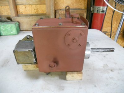
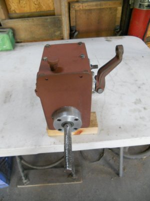
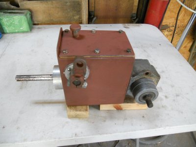
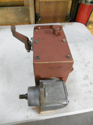
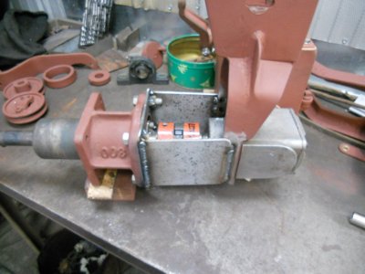
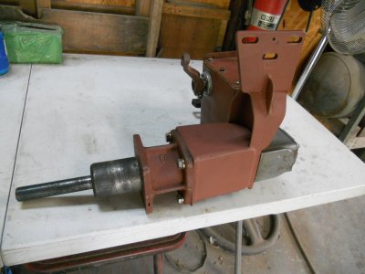
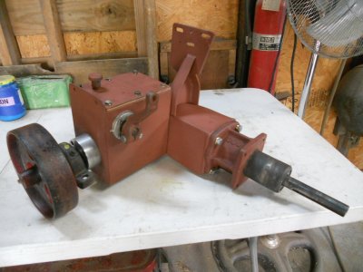
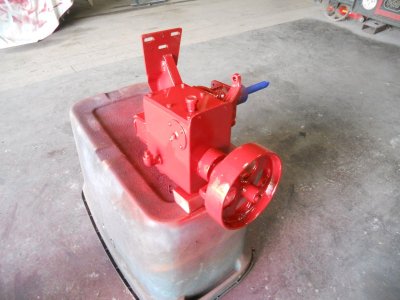
I'm going to make some drastic changes to the design of the flat belt drive system.
Yesterday, someone on another forum asked about the possibility of putting some sort of dog clutch on the drive pulley on the engine so it could be disengaged from the engine when I wanted to stop the belt.
This would keep the belt on the pulley because the pulley would also be stopped from moving.
With doing that, the belt tensioner could be set to hold pressure on the belt all the time.
It's and interesting idea but not really feasible in this case because the end of the crankshaft is flush with the end of the pulley. The end of the engines crankshaft would have to be sticking out past the pulley far enough to mount the dog clutch assembly on it.
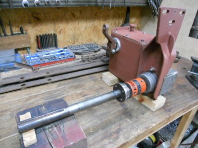
Thinking about this later, I realised that while the dog clutch will not work on the engine pulley, it will work on the shaft under the tractor that goes between the bottom pulley and the right angle gearbox.
I also remembered that I just happen to have the two mating parts for a dog clutch.
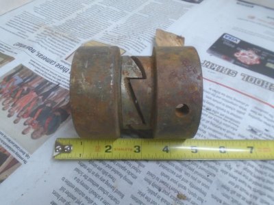
So ... with adding the dog clutch to the lower drive shaft, the belt tensioner will no longer engage and disengage the belt.
It is now be set so the belt is engaged all the time.
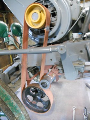
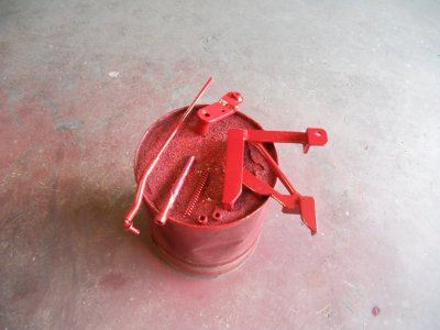
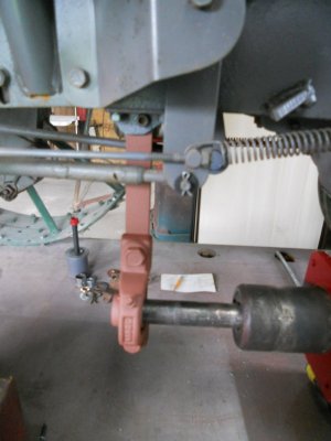
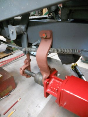
I have a fixed position, spring loaded rod mounted under the tractor that is connected to the tensioner lever arm.
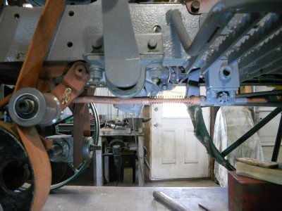
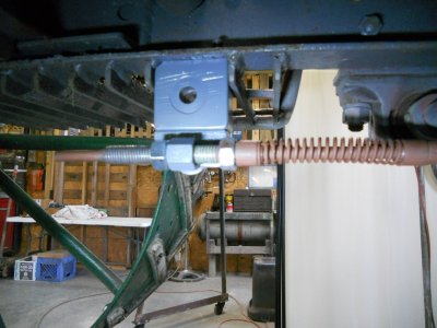
The other end of this rod slips thru a threaded rod. The spring tension is adjusted by turning the nut on the right end of the threaded rod. Once the tension is set, the threaded rod is locked in place with the a locknut of the left side up against the threaded bracket.
After everything was assembled, I saw that there is room to put the locknut on the right side of the threaded bracket so I'm going to switch that locknut.
This will allow more of the threads on the rod to be holding the spring pressure.
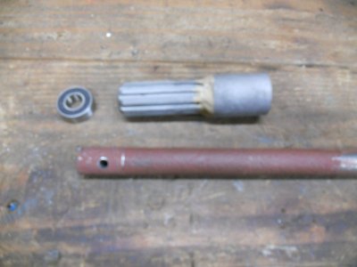
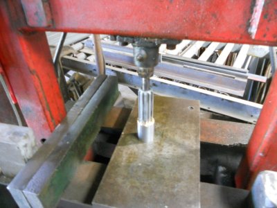
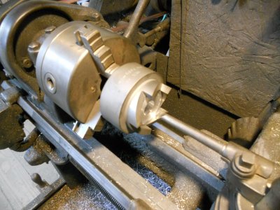
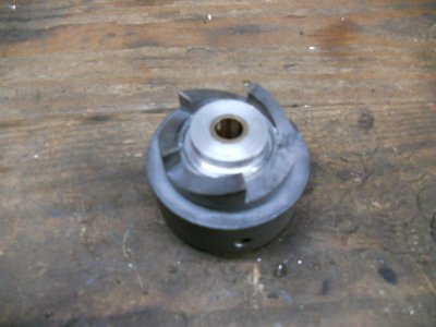
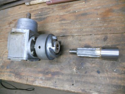
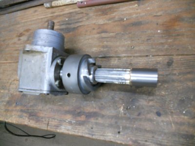
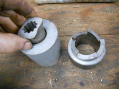
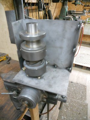
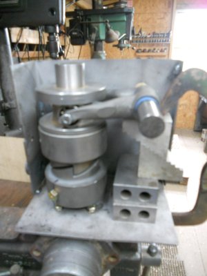
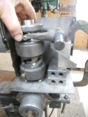
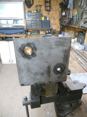
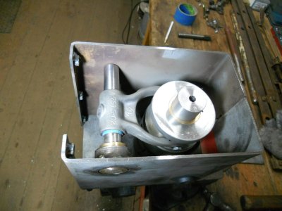
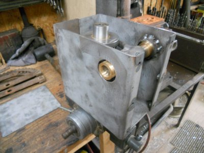
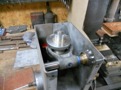
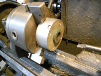
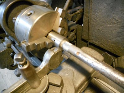
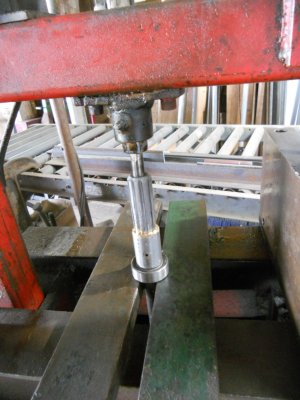
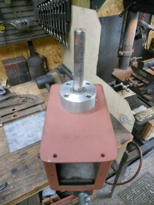
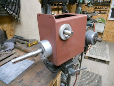
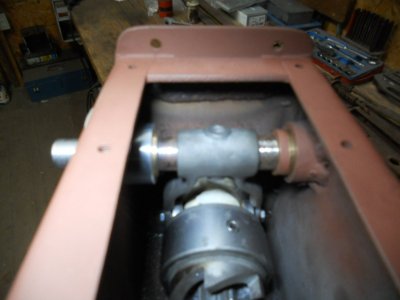
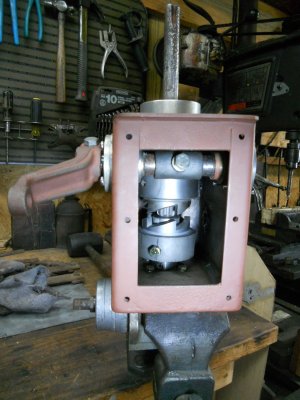
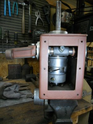
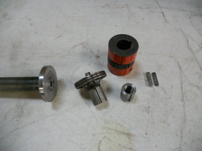
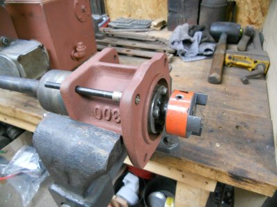
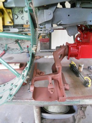
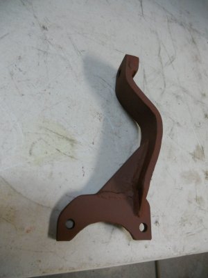
These are the parts to make the dog clutch work :
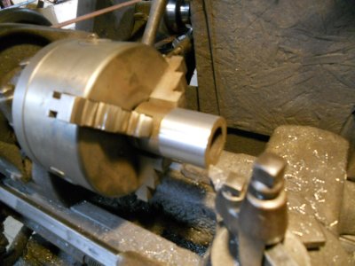
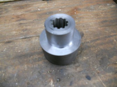
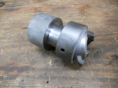
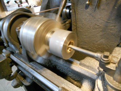
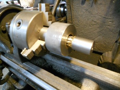
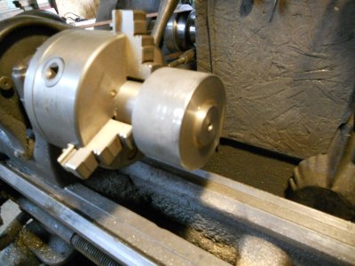
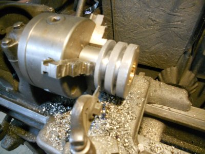
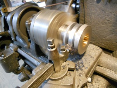
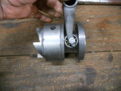
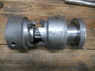
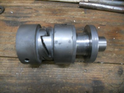
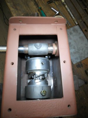
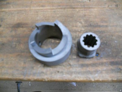
The two dog clutch halves.
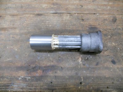
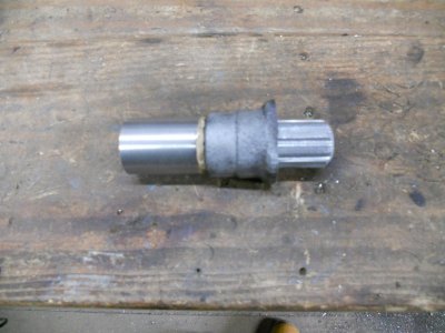
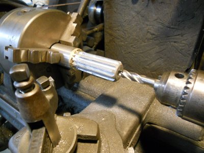
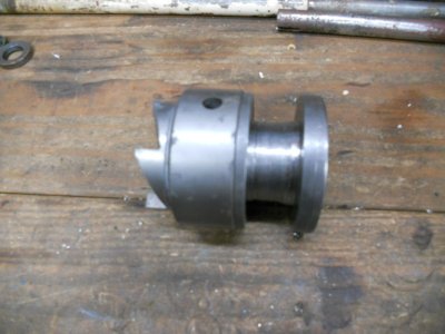
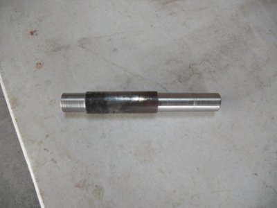
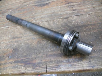
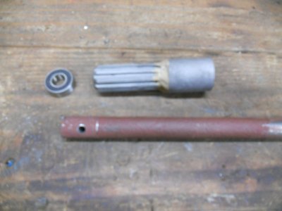
A splined shaft with a splined collar to fit onto it ( parts off a Ford model-T driveshaft and universal joint ).
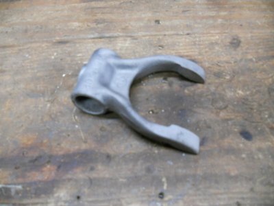
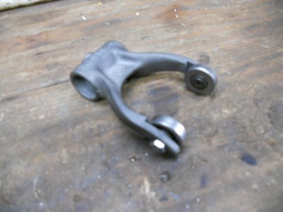
A clutch throwout bearing fork to move the one side of the dog clutch in and out ( off a Ford model-A ).
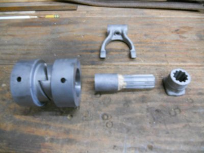
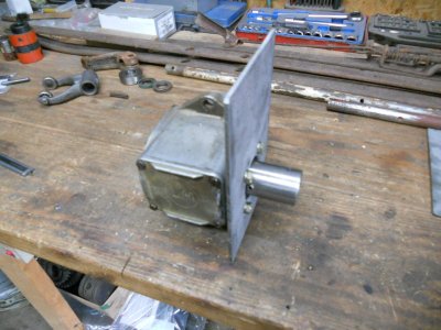
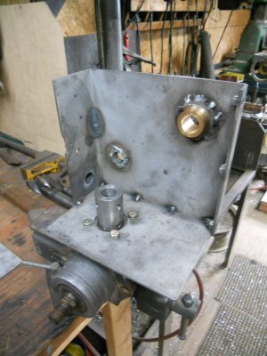
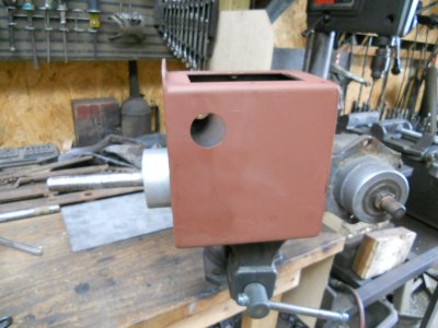
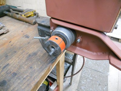
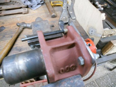
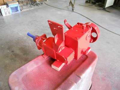
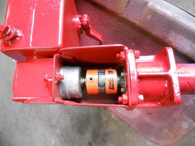
One half of the dog clutch will be mounted on the input shaft of the gearbox.
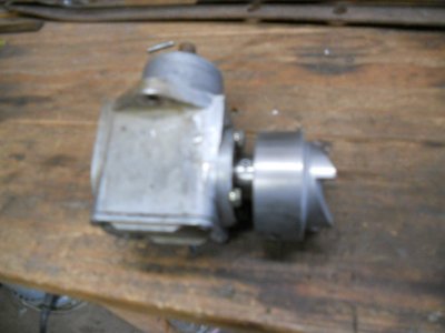
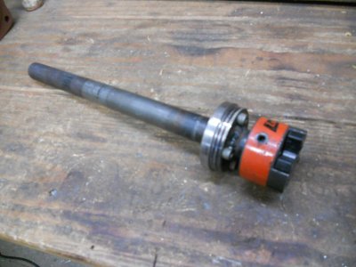
The other half of the dog clutch will have the splined collar fit inside it.
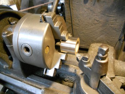
The splined shaft will be fit onto the drive shaft.
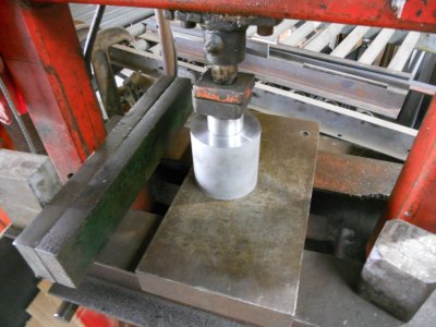
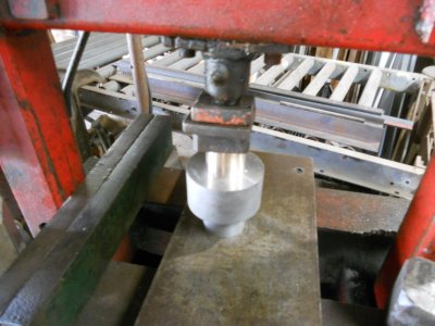
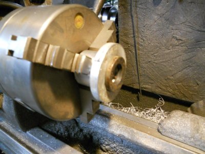
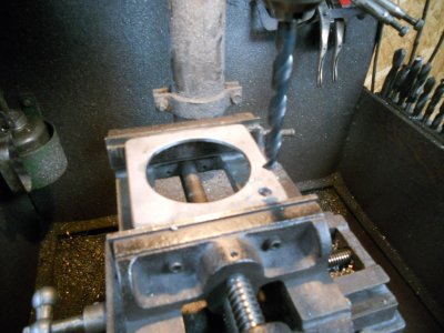
A bearing will be fit inside the dog clutch that will be on the gearbox and the end of the drive shaft will fit into it so that the shaft will spin on the bearing when the dog clutch is disengaged.
Yesterday, someone on another forum asked about the possibility of putting some sort of dog clutch on the drive pulley on the engine so it could be disengaged from the engine when I wanted to stop the belt.
This would keep the belt on the pulley because the pulley would also be stopped from moving.
With doing that, the belt tensioner could be set to hold pressure on the belt all the time.
It's and interesting idea but not really feasible in this case because the end of the crankshaft is flush with the end of the pulley. The end of the engines crankshaft would have to be sticking out past the pulley far enough to mount the dog clutch assembly on it.
Thinking about this later, I realised that while the dog clutch will not work on the engine pulley, it will work on the shaft under the tractor that goes between the bottom pulley and the right angle gearbox.
I also remembered that I just happen to have the two mating parts for a dog clutch.

So ... with adding the dog clutch to the lower drive shaft, the belt tensioner will no longer engage and disengage the belt.
It is now be set so the belt is engaged all the time.

I have a fixed position, spring loaded rod mounted under the tractor that is connected to the tensioner lever arm.

The other end of this rod slips thru a threaded rod. The spring tension is adjusted by turning the nut on the right end of the threaded rod. Once the tension is set, the threaded rod is locked in place with the a locknut of the left side up against the threaded bracket.
After everything was assembled, I saw that there is room to put the locknut on the right side of the threaded bracket so I'm going to switch that locknut.
This will allow more of the threads on the rod to be holding the spring pressure.

These are the parts to make the dog clutch work :
The two dog clutch halves.
A splined shaft with a splined collar to fit onto it ( parts off a Ford model-T driveshaft and universal joint ).
A clutch throwout bearing fork to move the one side of the dog clutch in and out ( off a Ford model-A ).

One half of the dog clutch will be mounted on the input shaft of the gearbox.

The other half of the dog clutch will have the splined collar fit inside it.

The splined shaft will be fit onto the drive shaft.
A bearing will be fit inside the dog clutch that will be on the gearbox and the end of the drive shaft will fit into it so that the shaft will spin on the bearing when the dog clutch is disengaged.


