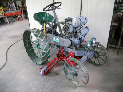
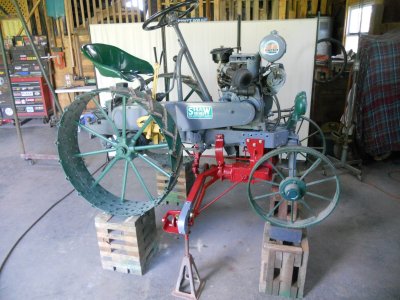
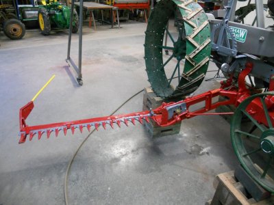
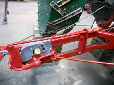
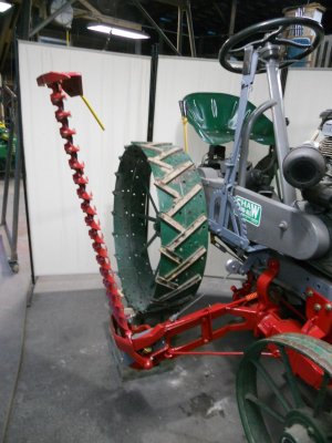
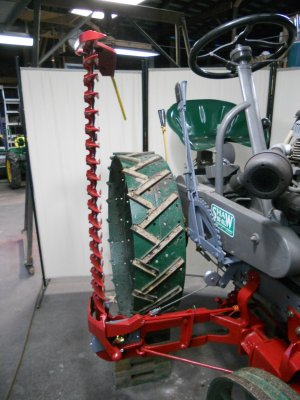
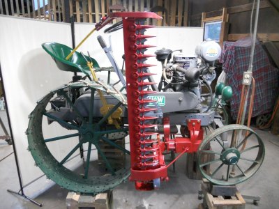
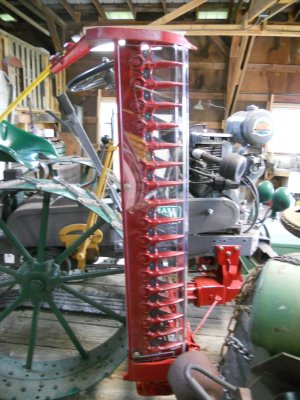
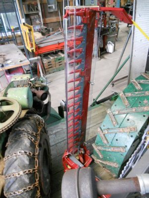
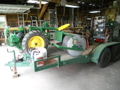
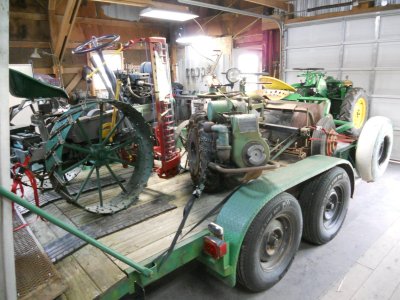
sickle mower

Worked on getting the linkage made up for operating the mower clutch today.

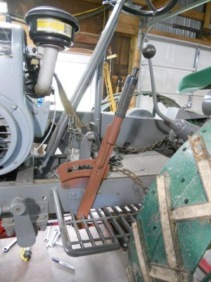
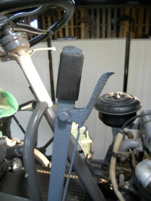
To operate the mower clutch, I'm using the same lever that I had originally made up for tensioning the flat belt.
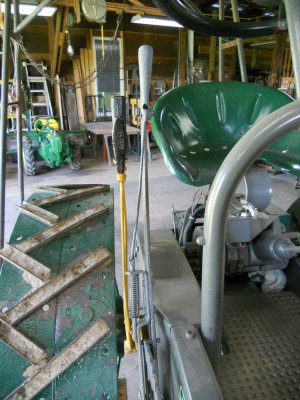
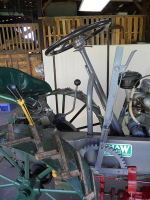
This is the position of the lever with the clutch disengaged.
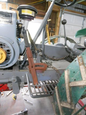
DSCN1445.JPG


And this is with it engaged.

DSCN1446.JPG


The movement on this lever is forward and backward and the movement of the clutch arm on the clutch case is side to side.
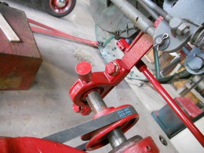
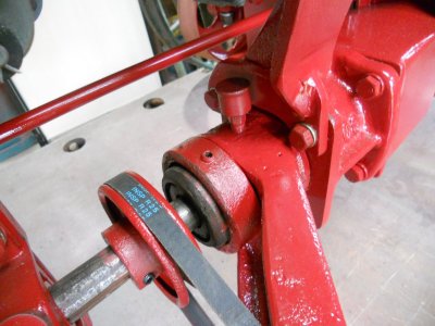
So first I made up this shaft with two arms on it.
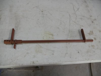
DSCN1437.JPG


This is mounted on the right side and fastened to the mower drive unit mounting brackets.
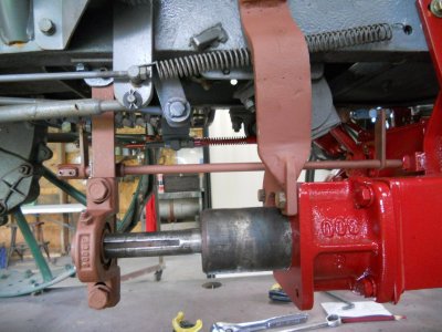
DSCN1438.JPG


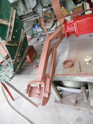
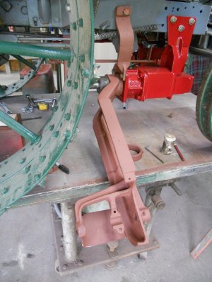
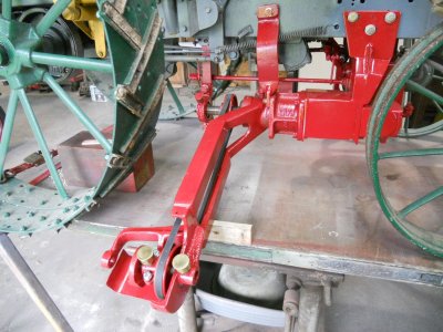
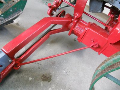
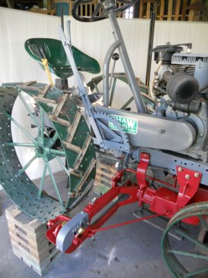
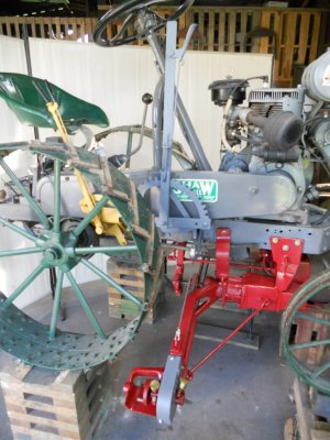
I'm using a triangular shaped bellcrank to change the forward and backward movement of the clutch lever to a side to side movement.
This bellcrank is mounted under the step on the left side.

You can see a linkage rod connected to the bottom of the clutch lever and going to one end of the bellcrank.
The linkage rod that is connected to the other end of the bellcrank runs over to the other side of the tractor.
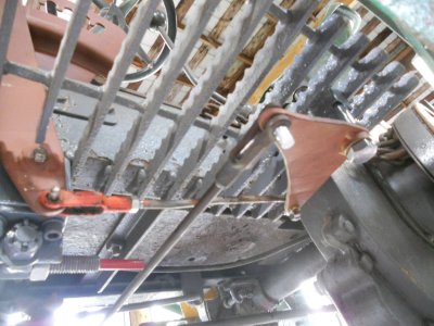
DSCN1439.JPG


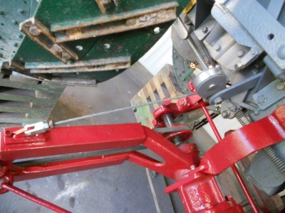
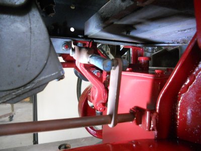
This rod coming from the bellcrank connects to this rear shaft arm.
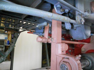
DSCN1440.JPG

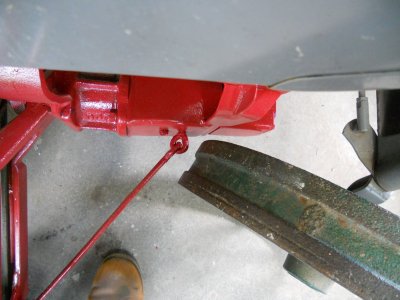
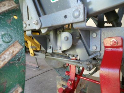
The front arm on this shaft has a linkage rod connected to it that goes to the clutch lever on the side of the clutch case.
DSCN1443.JPG
 
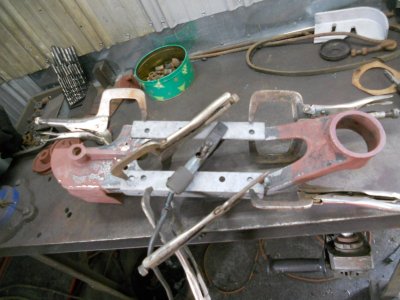
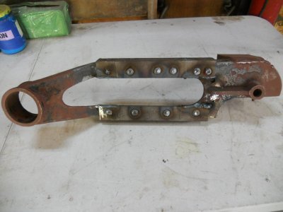
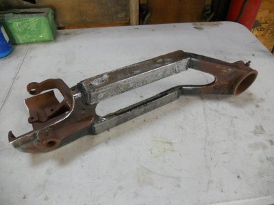
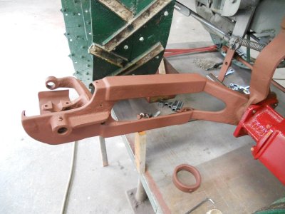
I have extended the sickle bar mounting bracket by 6 inches.
Here it is with pieces of angle iron clamped to the outside of it and ready for welding.

DSCN1447.JPG


These pieces are all welded in place using a combination of pocket welds and welding along the sides.

DSCN1448.JPG


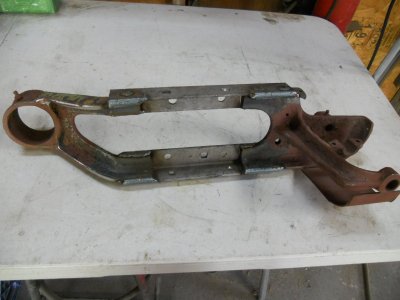
Then pieces of angle iron are added to the inside to fill in the space.
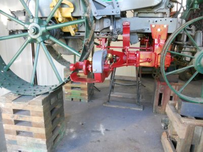
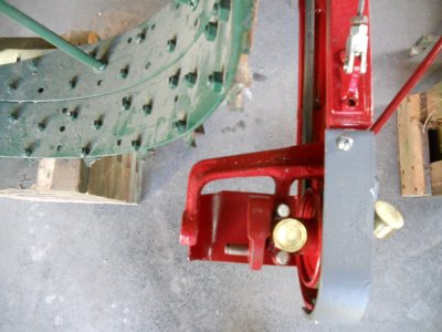
These are welded with butt welds on the inside ends.
DSCN1450.JPG


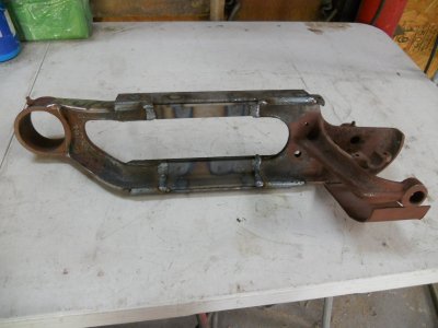
And pocket welds on the outside.

DSCN1451.JPG


All the welds are ground down and the open seams on the ends and along the sides are filled in with JB-Weld to seal them so moisture doesn't get in between the pieces of angle iron.

DSCN1453.JPG


The modified bracket is set onto the mower drive unit.

DSCN1455.JPG


The extended arms are twice the thickness that they were before.

DSCN1456.JPG


When it is lifted up, the new bracket now clears the rear wheel.

DSCN1458.JPG
 
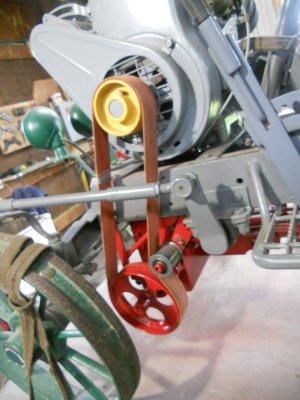
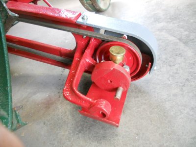
The flat belt is put back on connecting the engine to the drive pulley for the sickle mower.

DSCN1460.JPG


The mounting bracket for the sickle bar is installed back onto the mower drive unit.

DSCN1461.JPG


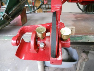
I have taken out the grease gun fittings and replaced them with old style grease cups.
With the tractor being a 1937 model, this type of grease fitting looks more appropriate.

DSCN1462.JPG


I also replaced the grease fitting on the shaft bearing.

DSCN1463.JPG


And on the hub that the bracket rotates up and down on.

DSCN1464.JPG


Link to my Youtube video of test run on mower drive.

 
The tractor is back down on the floor.

DSCN1465.JPG


The angled support rod is attached to the mounting bracket.

DSCN1465-1.JPG


Here is the clearance for the front wheel when turning.

DSCN1466.JPG


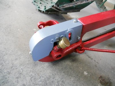
I have the guard mounted over the pulley for the sickle drive.

DSCN1468.JPG

DSCN1469.JPG


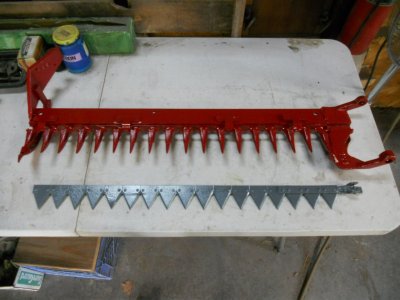
The parts for the sickle are also painted.

DSCN1470.JPG


Now to start working on how to raise and lower the mounting bracket and also the sickle bar.

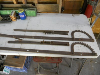
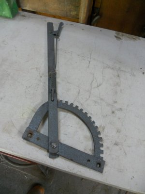
I have a pair of old operating levers that I picked up some time ago and I think I can use one of these to raise and lower the mounting bracket.

DSCN1471.JPG


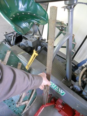
The problem is that the tractor seat is at the back of the big rear wheels and the pivot point for the lever would have to be at the front of the wheel.
That right away puts the lever a long ways from the seat and the parking brake is also mounted on that side so I need to allow clearance for operating that.

DSCN1472.JPG


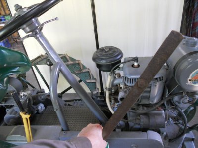
With the lever rotated forward, it puts the handle up by the engine and that position would be almost impossible to reach from the tractor seat.

DSCN1473.JPG


Still, I think I can make the one lever work fine for controlling the mounting bracket.
The bracket only goes up and down about 6 or 8 inches so there wouldn't have to be very much movement in the lever handle to do that.

Raising and lowering the sickle bar is another matter.
That has a good 90 degrees of movement and there just isn't enough room for a second operating lever to make that much movement.

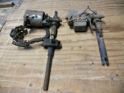
I do have a couple of old electrical powered screw jacks and maybe I could use one of them for controlling the movement of the sickle bar ?

DSCN1474.JPG
 
Looks like you have a few levers to grab, what if you went with a pedal lift system? If I recall right, Deere and IH used pedal lifts on the old horse drawn sickle mowers. I think you would get some more range of motion, also with your foot on the pedal, you could quickly lift the sickle bar over a obstacle while your cutting. Just a thought JD.
 
Looks like you have a few levers to grab, what if you went with a pedal lift system? If I recall right, Deere and IH used pedal lifts on the old horse drawn sickle mowers. I think you would get some more range of motion, also with your foot on the pedal, you could quickly lift the sickle bar over a obstacle while your cutting. Just a thought JD.

Interesting idea.
 
The tractor is back up on shorter stands for the work to be done now.
The sickle bar mounting bracket is set at the same level as the bottom of the wheels ( ground level )

DSCN1475.JPG


I have sandblasted one of the levers and it is painted with one coat of paint and put back together.
There is still machine work and welding to be done so final coats of paint will be put on when everything is finished.

DSCN1477.JPG


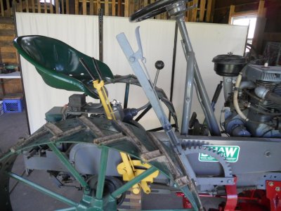
This is mounted on the side of the tractor.
This is the position it will be in when the mounting bracket is raised all the way up.
The hand brake lever is in the off position here and is within easy reach from the tractor seat.

DSCN1478.JPG


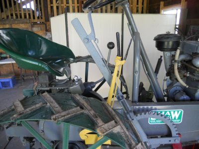
When the handbrake is applied, the lever comes forward up along the outside of the other lever.

DSCN1480.JPG


Here you can see the clearance between the two levers.

DSCN1481.JPG


I'm figuring that with the mounting bracket lowered all the way down to the ground that the lever should probably be positioned about here, still easily reachable.

DSCN1482.JPG


This lever is mounted to angle brackets that are bolted to the side of the tractor frame.

DSCN1484.JPG
 
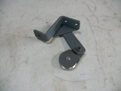
I took the front mount off the lever and added a cable pulley to it.

DSCN1485.JPG


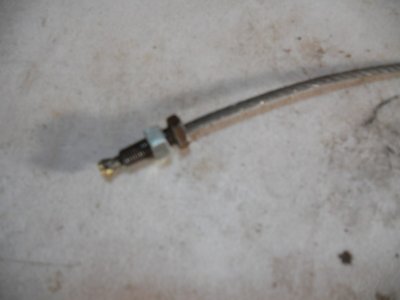
Then I made up a short cable.
This was done by drilling a hole thru a couple of bolts.
The cable is slid thru the hole until about 1/8 inch of cable sticks out past the bolt.
Then the strands on the end of the cable are spread out and are brazed so there is a ball on the end of the cable that is larger than the hole in the bolt.

DSCN1486.JPG


One end of the cable is fastened to the lever and the other end is fastened to the sickle mounting bracket.

DSCN1487.JPG


Pulling the lever back raises the mounting bracket up.

DSCN1488.JPG


With the bracket up, it is about 6 inches off the ground.

DSCN1489.JPG


This is the clearance between the bracket and the wheel with the bracket raised all the way up.

DSCN1492.JPG


Moving the lever forward 5 notches lowers the bracket to the ground for what will be the mowing position.

DSCN1490.JPG


The lever stays within easy reach from the tractor seat.
I have forced a piece of rubber hose down onto the lever for a handle.

DSCN1494.JPG


I have been trying to figure out how to mount a second lever for lowering and raising the sickle bar from vertical traveling position to horizontal mowing position.

Looking at garden tractor sickle mowers on the internet I realised that on every one that I looked at, the sickle bar itself is lowered down to mowing position and raised back up to vertical position manually, not by another lever.
Some of them have a long handle mounted on them but that is only to help moving the bar manually so you don't have to grab hold of the sickle bar itself.

Trying to remembering way back when I built that little Sears with the sickle mower and I'm thinking that I had to get off the tractor and move the bar manually.
Once it was down in mowing position, I think there was a lever that would raise the whole thing up a little, but I'm not sure ??
It's hard to remember much about that Sears tractor because it was sold within about a week after I finished building it and I never really used it much.

So .... rather than fussing with some way of moving this sickle bar with a lever or jack screw, I'm going to leave it manually operated like all the other sickle mowers that I've seen.
 
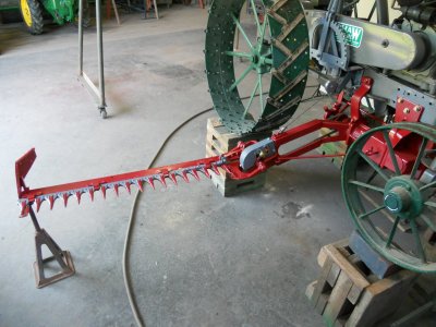
The sickle bar is mounted and the end of it is supported on a stand.

DSCN1495.JPG


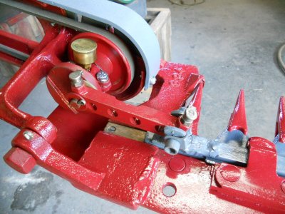
I have put fliptop oil cups on over the bushings on the pitman arm.
These hold 85W-140 gear oil to lubricate the bushings.

DSCN1496.JPG


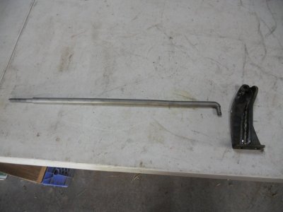
This is a bracket and rod that I made up.

DSCN1497.JPG


The bracket bolts to the end of the sickle bar near the pivot point.
The bent end of the rod fits into a hole in the top of the bracket and the rod extends out along the top of the sickle mounting bracket.
There is a piece of angle iron bolted to the side of this bracket and the rod goes thru a hole in the angle iron with a very heavy duty spring fastened to the end of it.
This spring is adjustable to control how much weight is on the outside end of the sickle bar.

Note: there is no support stand under the end of the sickle bar and it is sitting level.
There is still enough movement in the spring that I can push the end of the bar down about 3 inches and it goes back up to this position when I released it.

DSCN1498.JPG

DSCN1499.JPG


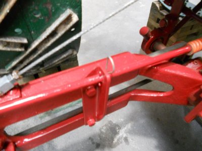
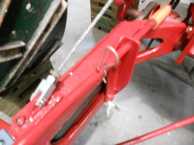
When the sickle bar is raised up, a clip pin is slid into a hole in the rod to keep the bar in the up position.

DSCN1500.JPG


With the bar raised up, then it is easy to pull the lift lever back and raise the whole thing up off the ground.

DSCN1502.JPG

DSCN1503.JPG


The bar is held in position by a cotter key thru a hole on this side of the angle iron and the clip pin on the other side.
This keeps the bar from moving in or out.

DSCN1504.JPG


To lower the bar, pull the clip pin out and then put that pin back in its hole after the bar has been lowered so the pin doesn't get lost.

DSCN1505.JPG
 
My son works for a company that has a plastics division and he got this sickle bar guard formed up for me.
It is made out of 1/4 inch thick Plexiglass.
The mower can be operated with the guard on it to show people how the cutter blade works.

DSCN1509.JPG

DSCN1510.JPG


There is a small local tractor show on Saturday so I have the trailer all loaded.

DSCN1512.JPG

DSCN1513.JPG
 
Back
Top