Stage-2, Complete K66 Oil Change Guide GT/TS, Center Console Removal

GT48DXLS

Tractorologist
Senior Member
Member
STAGE-2

Disassembly as Necessary for Transaxle Maintenance. Easy as 1-2-3…..

Prep for Center Console Removal

1) Disconnect front lights from wire harness.

1.JPG

2) Remove Hood, place out of the way, safe. This is prone to scratches.

2.JPG

3) Secure the front wheels with chocks, wood, rocks, etc.

3.JPG

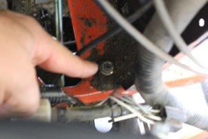
4) Place the transaxle in free wheel mode, pulling this metal rod back until you feel a mechanical switch type release.

Engaged looks like this,

4.JPG

Disengaged looks like this, (Do This)

5.JPG

This is a transaxle safety precaution, prior to rear wheel removal, and for complete hydro chamber draining.

5) Loosen rear wheel lugs before lifting the tractor, we are not removing yet. You will need a 5/8” socket and a 6” extension in either 3/8” or 1/2” wrench for the bolt heads. I loosened a 1/4 to 1/2 a turn in a star pattern so force is released in an even way. I will say that at 65 ft lbs of torque it is probably redundant, but its a good habit to prevent warping a hub/wheel.

6.JPG

Remember stripping the tractor of weight in the beginning? Here is your payoff.

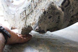
6) Lift the rear end of the tractor up safely with a block of wood like this here. This will spread the weight evenly and safely with a floor jack. The goal is to lift high enough to slip the rear wheels off, and still low enough to be level for the transaxle fill.

7.JPG

Kinds of affordable floor jacks,

Floor Jacks.png

This is a good hieght,

8.JPG

You can use bottle jacks, but it will get difficult. I recommend a floor jack for this. If you don’t own one, now may be the right time to clip a coupon and get one. It doesn't have to be fancy but it is very stable.

I use this type of jack now, (another use for a Johnny Bucket power sleeve....built in tractor jack!).

Continued on next post.
 

Attachments

  • 12.JPG
    12.JPG
    67.2 KB · Views: 6
Stage-2 Continued..

7) Rest the chassis on a cinder block with a piece of wood like this, Pay attention that your control rod is free to move, twisting from side to side in small movements, not bending under weight. Also your brake rod should have plenty of play too, up and down. This configuration will be very stable and when you remove the floor jack, you will have plenty of space for draining.

Notice here how the small top block allows the control rod to rest normal, not on the wood,

9.JPG

10.JPG

1= 16”x8”x8” cinder block, as common in box stores for a couple bucks.
3=2”x6”x16” pieces of wood.
2=2”x4”x4” blocks of wood for resting the chassis on.

The specifics of what I used is less important than creating a stable brace under the chassis where the chassis has support and the control rod is not being bent. This guide is what I used, in keeping with the goal, average and common. It works well.

11.JPG

8) Remove wheel bolts, and wheels. If you place the bolts in the hubs after you have removed the wheels, you will keep the bolts safe and not lose them. Very tidy and ready for install.

13.JPG

If they need cleaning, like mine did, we can do this later all at once to save time.

Center Console Removal.

1) Disconnect negative battery cable, my bolt size was 11mm or 7/16” for both. They were stock bolts, should be the same.

14.JPG

2) Disconnect positive battery cable.

15.JPG

3) Remove battery and place out of the way on wood or something but the ground. If you have a battery tender, this is the perfect time to connect your battery to it.

16.JPG

I upgraded my battery to a Harbor Freight Solar AGM because of the increased electrical loads that the Johnny Bucket Jr uses, it’s a small modification for those interested. You will need to get a longer positive cable and negative cable because the positive terminal on the HF battery is on the opposite side from the stock battery. If you do this I also recommend a larger cable diameter of 4ga, still simple but would give you room for electrical upgrades in the future.

This battery is a U1 500 cca 35AHr battery that will absorb shock well and is a worthwhile improvement over the stock battery. It will also last longer and if you have the Kawasaki it meets the minimum AHr requirement that Kawasaki has for their motor. It’s in the Kawasaki supplemental engine manual if your curious.

I tell you this to make you aware but also the battery will be different than most, don’t get hung up on the difference.

A battery tender is not a charger (by design) or a trickle charger, it monitors the natural release of electrons during storage and replaces what is lost. When nothing is lost it will stay at rest, very healthy for a lead acid battery. A trickle charger can over charge a small lead acid battery, if you know how to use one they work, but a tender or battery minder takes all the work out of it, just a thought.

4) For the battery tray removal I like using a 1/4” drive with 3/8” deep socket, but a 3/8” end wrench or small adjustable will work fine on the two bolts that fasten the battery tray. Lift tray out and replace the 2 bolts in there spot for re-installation.

17.JPG

18.JPG

Note- If you have a similar Johnny Bucket wiring harness, this is a good time to disconnect and remove.

5) Pull out the choke as if you were starting the engine. If you don’t have a choke, one less step.

19.JPG

Stage-2 Continued in the next post.

 
Stage-2 Continued...

6) For the Kawasaki the choke cable is on top at the support plate here,

20.JPG

7) lets clean it here if you need to, I did.

23.JPG

A little redundancy here will help you re-install later like a pro.

This paint pen is handy here, or a sharpie will work too. When using a sharpie, be careful not to handle a sharpie mark with grease or oil. The sharpie mark can rub off.

21.JPG

WD-40 as an example is a listed solvent, (cleaner).

For cleaning this type, I like using denatured alcohol, because it dries completely and fast. Water works too. Denatured alcohol is a common recommendation for cleaning sharpie or other marks and smudges off a dry erase board, it works well.

22.JPG

Here is how I mark it,

24.JPG

Now it’s ready for removal,

Important- For this next step,

Only loosen when the marks you made are dry.

8) Torx 25 is required here, Torx is now common on many vehicles, and T25 is the most commonly used size in my tool box. If you don’t have a basic Torx set, this money won’t be wasted.

This is a Craftsman style,

25.JPG

There are many that will work.

Loosen the Torx head screw enough to remove the cable, no need to remove the screw. Remove the thin cable from the locking cable housing and the carburetor choke control arm. Having the choke pulled prior helps to minimize the thin exposed part of the cable and offers some protection from being bent. When a cable like this bends (kinks) it is most likely ruined.

26.JPG

27.JPG

9) now remove the throttle control cable while you have set it first to full throttle, again cable protection.

28.JPG

And,

29.JPG

Stage-2 Continued on the next post...


Stage-2, Continued...

10) Clean the lower cable on the cable lock plate, and paint each side (mark with Sharpie or paint pen), use the same Torx 25 to loosen when dry. Carefully remove the throttle cable from the carburetor throttle control lever.

30.JPG

Make sure the removed screws go back in there places,

31.JPG

Time to start the electrical harness disconnect process.

11) In this picture there are three connectors to disconnect , and the main power cable needs to be disconnected from the starter. This is on the right side.

32.JPG

I used an 11mm end wrench (7/16” end wrench or adjustable will work) for the starter top nut, on the main power stud where the main power wire to the starter is mounted. Undo the top nut only, you may have to have a wrench on the second nut to hold it steady if there is some corrosion. Remove the wire and replace the top nut, it should look like this,

33.JPG

The next three connectors require 2 fingers to pinch like this,

34.JPG

Carefully wiggle the connectors loose. This should not take a lot of effort, if it does make sure the connector locks have released.

12) Disconnect the PTO,

35.JPG

13) Charge Coil, (Stator)

36.JPG

14) Rear electric supply,

37.JPG

Time for wire cutters, the idea here is to cut all zip ties that are in place for wire harness vibration control. We will replace later during assembly. Some people may have more or less, depending on who assembled the machine. We are isolating the center console as one big unit to save time on disassembly and re-assembly. (it’s easier to keep track of one piece than many, individual small pieces)

38.JPG

15) Cut this tie on the PTO if it’s there,

39.JPG

Be careful not to cut the wire.

Stage-2, Continued on the next post...
 
Stage-2, Continued...

16) Time to free the front lights wire loom,

The loom should have 2 one way push anchors securing it to the chassis top, here,

40.JPG

Examples of tools designed to be used for these types of plastic one way anchors. They are commonly found at most auto stores or tool stores like HF. These are a great cheap investment for any household, car interior panels and such. (Straight blade screw drivers can be used, but tend to break them, so be careful with a screw driver)

41.JPG

42.JPG

43.JPG

Here is another style of one way anchor, it has 2 prongs or barbs that when pinched from underneath will allow the anchor to release while simultaneously lifting up and out.

44.JPG

45.JPG

Another look at the difference between the 2 styles,

46.JPG

17) The interlock switch is located here,

47.JPG

It reads the brake pedal engagement. This switch has a fragile release style of plastic clasp. Be gentle and don’t bend too far, just enough here,

47.JPG

Wiggle it free, it should look like this, when done,

48.JPG

This wire is also secured to the chassis by the barb style of one way anchor, reach underneath, pinch the barbs in and pull up,

49.JPG

Stage-2, Continued on the next reply...


Stage-2, Continued...

18) Unbolt the main electrical harness grounds here,

50.JPG

1/2” (13mm) socket,

51.JPG

Replace the bolt when done.

52.JPG

As far as the electrics for center console removal is concerned, your done!

19) Disengage cruise control rod here,

53.JPG

Pull out the small quick release pin, slide the rod out of the spring loaded top tooth arm and put the pin back in the rod.

54.JPG

19) This is a low profile quick release pin on the parking brake control rod, I use needle nose pliers to pop this off,

58.JPG

55.JPG

56.JPG

57.JPG

re-install the pin,

59.JPG

Almost done!

Stage-2, Continued on the next reply...


Stage-2, Continued...

20) There are 2 9/16” bolts on the lower steering gear bearing to steering support plate,

60.JPG

with a 9/16” socket remove these bolts, then lift up on the steering shaft enough to replace the 2 bolts and ready the shaft for console removal making sure the shaft won’t get hung on anything,

61.JPG

62.JPG

63.JPG
21) Time to remove the four 1/2” (13mm) bolts securing the rear of the center console, and two 1/2” (13mm) nuts that secure the center console in front, all on the base of the console from inside.

63.JPG

2 bolts on this side, Left side,

64.JPG

2 bolts on this side, Right side,

63.JPG

2 nuts on studs, front,

1 here,

67.JPG

1 here,

66.JPG

Be careful not to have the console move uncontrolled yet when removing the last 2 nuts.

Stage-2, Continued on the next reply...


Attachments

  • 65.JPG
    65.JPG
    44.2 KB · Views: 1
Stage-2, Continued...

22) Carefully tilt the center console back and up toward the operator seat and pull the console out. Make sure its gentle so as not to rub the two front studs harming the threads (if you do, don’t panic, common tap and die sets will solve this just fine) and at the same time making sure that wires aren't getting hung up or other strange things, but it should just come right out.

68.JPG

Place your center console in a suitable place safe and out of the way. It should look like this,
Minus the sand of course, hopefully.

69.JPG

The 2 nuts and 4 bolts holding the center console to the body to the chassis should go in a zip lock bag and label it something you will remember, or what I did,

70.JPG

Console, Body, to Chassis Bolts.

You are finished with Stage-2, I’m guessing at this point you have already accomplished something most people have never done, Congratulations. Good time to take a break or end the day.

Stage-3, Complete K66 Oil-Change Guide GT/TS, Body and Fuel Tank Removal
 
Back
Top