Stage-6, Complete K66 Oil-Change Guide GT/TS, Install Center Console-Function Tests

GT48DXLS

Tractorologist
Senior Member
Member
Stage-6

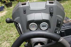
Center Console Install

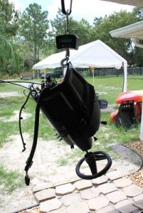
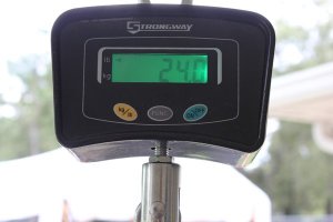
I gave the weight of the main body so that someone can know for themselves if they needed help on install by weight alone. I’ll give the center console weight for the same reason, Though easier, it may have some awkward moments too, while lining things up,

2.JPG

1.JPG

With a clean center console, give it a quick lookover and make sure it’s all there and ready for install. There are a lot of little bits here in a small space.

18.JPG

19.JPG

Time for the last “big” segment, the center console.

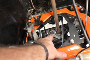
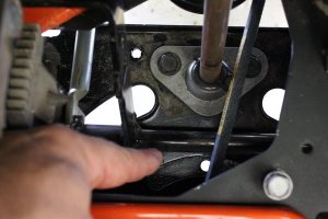
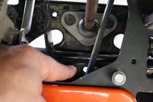
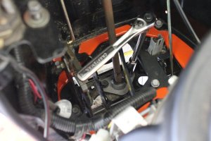
1) Remove the two bolts on the steering support plate that bolts the lower steering gear bushing housing to the steering support plate.Using the two front studs as an alignment for this process.

20.JPG

21.JPG

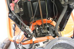
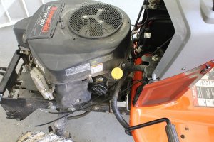
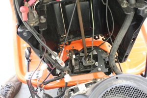
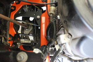
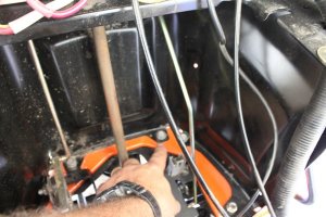
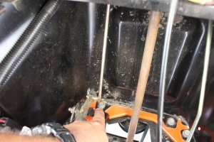
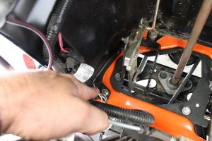
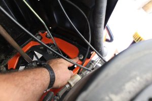
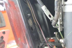
2) With the center console roughly in place have the choke, throttle cable set aside to the left of the motor,

24.JPG

25.JPG

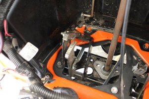
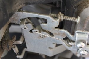
The parking brake rod is on the left,

30.JPG

31.JPG

Stage-6, Coninued on the next reply,
 
Stage-6, Continued...

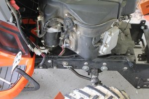
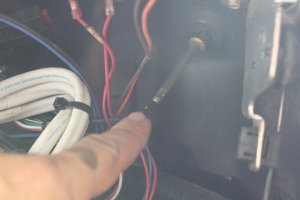
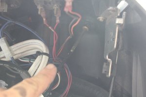
The main electrical harness on the right side of the motor,

23.JPG


The cruise control rod on the right,

29.JPG

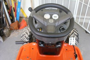
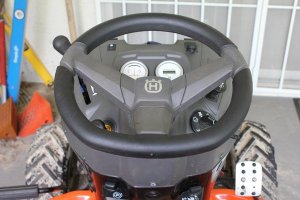
Orient the steering wheel straight,

22.JPG

Set Steering gear in it’s place,

21.JPG

32.JPG

While being careful not to crush your wires don’t crush the wires,

28.JPG

Because we don’t have a way of adjusting toe on our GT’s front wheels, there is a way to know they are as straight as possible.

33.JPG

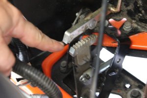
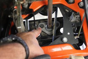
This hole in the toothed steering plate here,

34.JPG

Should line up with the front center corner of the lower steering bushing bracket here,

35.JPG

If these are lined up pointing center forward and your steering wheel is center, its as good as its gonna get, its aligned. If the wheel is not centered, now is the time to do this,

Stage-6, Coninued on the next reply,
 
Stage-6, Continued...

When all is centered,

3) Start both bolts (by hand) for the lower steering bushing bracket to steering support plate, don’t tighten yet,

37.JPG

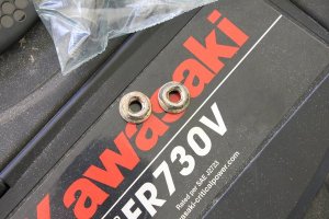
4) Start the two nuts on the chassis to body to console studs, don’t tighten but get them hand snug,

38.JPG

39.JPG

40.JPG

41.JPG

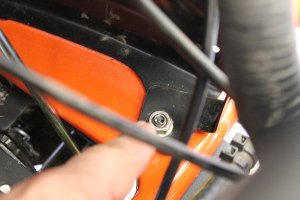
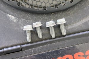
5) The last four bolts for the center console in the rear, get them started, by hand, console should be not move, but don’t tighten the bolt and nuts yet.

42.JPG

43.JPG

44.JPG

Stage-6, Coninued on the next reply,
 
Stage-6, Continued...

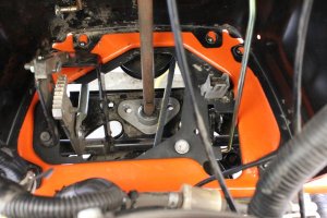
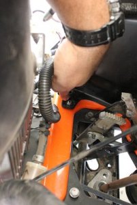
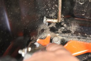
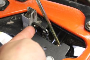
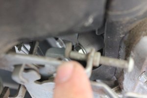
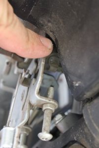
6) Attach cruise control rod,

45.JPG

46.JPG

47.JPG

48.JPG

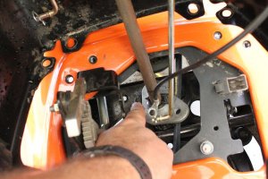
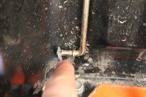
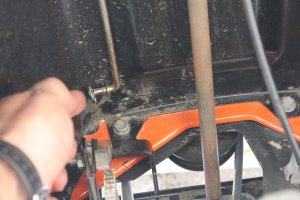
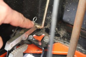
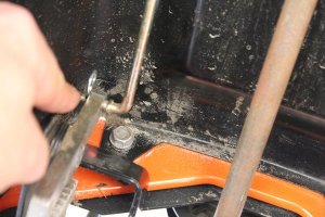
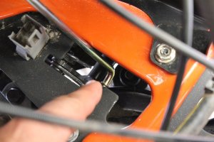
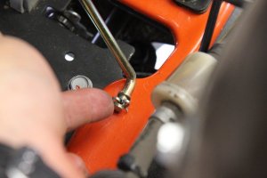
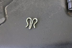
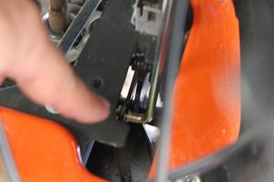
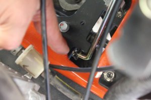
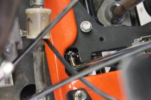
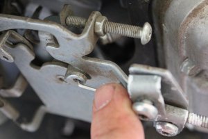
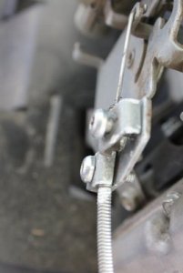
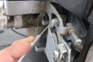
7) Attach parking brake rod,

49.JPG

50.JPG

51.JPG

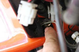
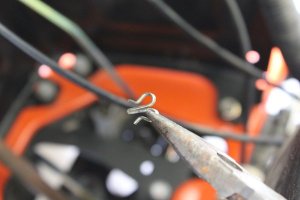
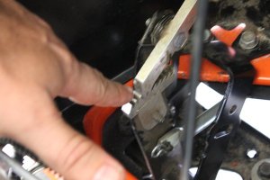
There are two holes, use this hole,

52.JPG

Use needle nose pliers here to insert, if fingers are big like mine,

53.JPG

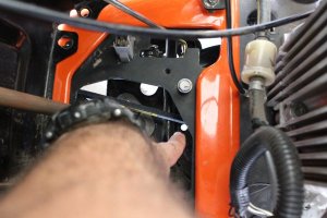
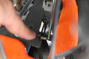
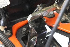
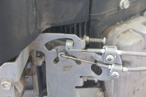
10) Check its function, when parking brake is not set,

54.JPG

Stage-6, Coninued on the next reply,
 
Stage-6, Continued...

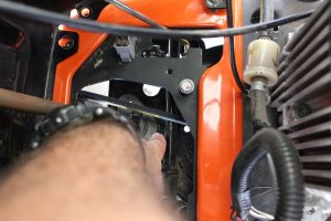
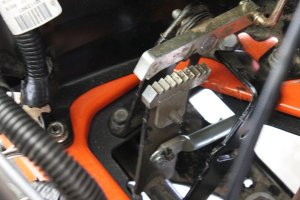
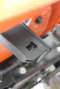
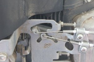
When parking brake is set, it looks like this, resting on the forward metal tab,

55.JPG

56.JPG


When pressing on the brake pedal it should release right away, and return, looking like this again,

54.JPG

11) Check cruise control function,

57.JPG

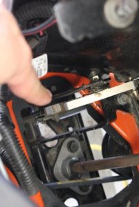
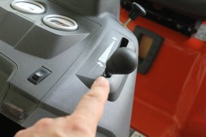
Set the cruise control by pressing the forward control pedal forward while you raise the cruise knob and hold while letting the forward pedal return to neutral, if its set it will look like this,

58.JPG

Cruise control not set, or when it’s released,

59.JPG

There are two function checks to perform.

1) While pressing on the forward control pedal, the cruise control top arm should release.
2) While applying the brake (brake pedal input) the cruise control top arm should release.

Here we go,

Set the cruise control,

58.JPG

Apply forward control pedal,

59.JPG

If it passed,

Reset the cruise control,

58.JPG

Apply brake pedal input, (notice a different way of clearing or releasing the cruise control?)

61.JPG

Cruise control released,

62.JPG

If your cruise control passed both tests, move on to the next step.

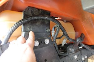
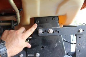
12) Tighten the 4 bolts at the rear inside of center console, tighten the two nuts on the front console studs, and make sure the 4 rear body bolts are tightened (remember the 2 on each side of fuel tank).

2-Right rear body bolts,

63.JPG

2-Left rear body bolts,

64.JPG


Stage-6, Coninued on the next reply,
 
Stage-6, Continued...

2-Left center console rear bolts,

65.JPG

2-Right center console front bolts,

68.JPG

1-Right front nut,

69.JPG

1-Left front nut,

70.JPG

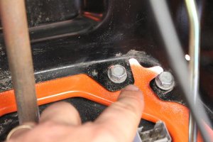
13) Tighten the two bolts that secure the lower steering bushing bracket to the steering support plate, as long as it still lines up. If not, take a moment and line it up. It should look like this,

74.JPG

75.JPG

76.JPG

If they all line up, tighten up,

71.JPG

72.JPG

73.JPG

Center console and inside mechanics are done.

Stage-6, Coninued on the next reply,
 
Stage-6, Continued...

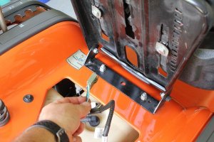
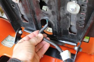
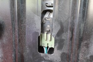
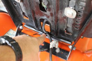
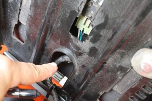
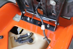
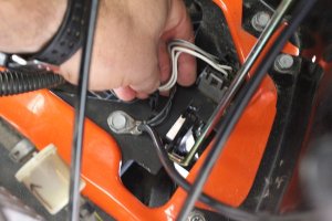
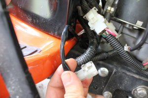
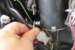
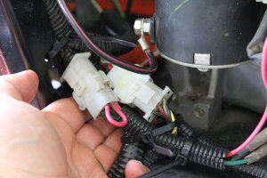
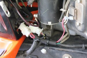
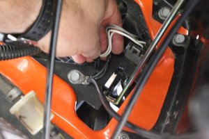
14) Secure the operator presence connector,

77.JPG

78.JPG

79.JPG

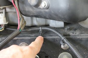
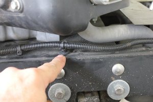
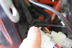
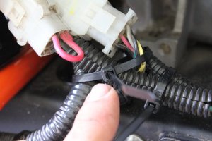
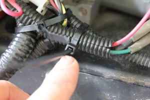
Zip tie the line here,

83.JPG

With slack on the line here,

84.JPG

This anchor can be put back, but I found it was stressed when checking the seat adjust-ability function, so I leave it like it is with some loose flexibility with the seat. Either way, but make sure the seat function works without pinching this wire.

82.JPG

15) Your in this area, make sure the main fuel line is secured,

88.JPG

16) Install mower deck lift hand grip,

89.JPG

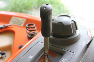
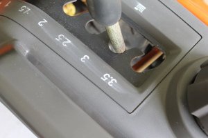
17) Make sure the mower deck height adjustment lever is locked/ secured in a channel so it doesn’t move on you unexpectedly in the next step.

90.JPG

The specific channel is not important (mine was on 3) just secured in a channel.

18) Remove or cut the wire that has been supporting the spring tension on the mower deck height adjustment lever, or cargo straps,

91.JPG

Stage-6, Coninued on the next reply,
 
Stage-6, Continued...

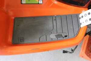
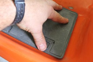
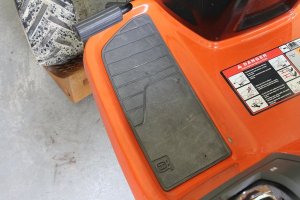
19) Reinstall body floor pan foot pads (if you cleaned them like I did, and hadn’t installed them yet),

92.JPG

93.JPG

94.JPG

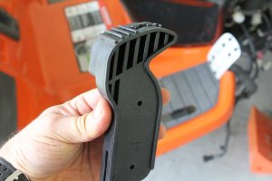
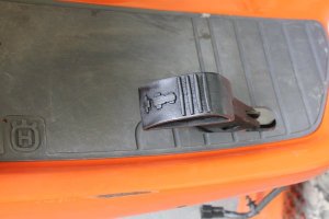
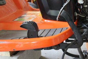
20) Reinstall reverse pedal, it should just pop in place,

Make sure the pedal arrow on top faces the rear, for its direction of travel.

95.JPG

96.JPG

Pressing it down until it clicks, like this,

97.JPG

98.JPG

Center console electrics-

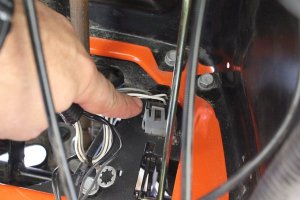
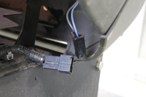
21) Connect interlock switch here, when pushing it on, support the switch, it could get pushed through,

100.JPG

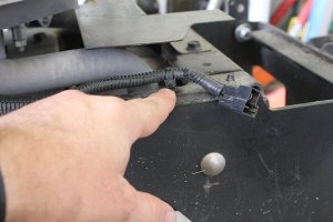
The interlock switch is the only one with a black male end on the harness,

99.JPG

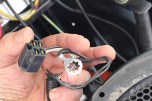
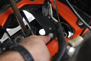
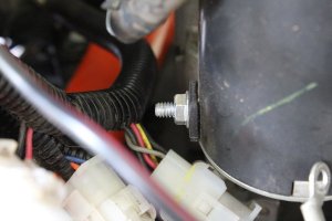
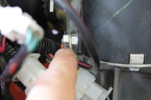
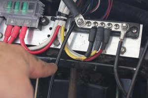
The ground to chassis bolt here, for both the main harness and battery ground wire/cable.

101.JPG

Stage-6, Coninued on the next reply,
 
Stage-6, Continued...

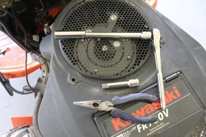
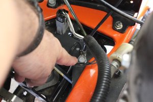
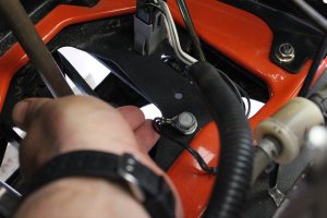
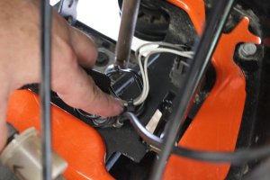
22) Connect the chassis ground and the battery negative cable with a 1/2” socket and extension, check your ground, is it clean? If yes, bolt them on,

103.JPG

102.JPG

Tip- I put the heaviest wire (battery negative cable) on the bottom and the lighter main electrical harness wire (the one connected with the interlock switch) on top so when you tighten the heaviest ground is in contact with the most surface area.

23) Push in the wire anchor for the ground and interlock switch,

104.JPG

105.JPG

24) Wire for hood front lights, 3 one way plastic chassis anchors, press them in,

108.JPG

109.JPG

110.JPG

It should look like this,

111.JPG

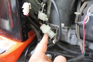
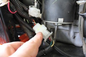
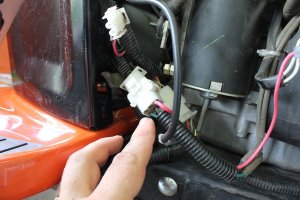
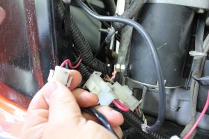
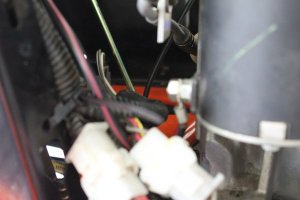
25) Rear electrics Connector, can only fit together one way, notice flat and round (square peg in square hole, etc)

112.JPG

Stage-6, Coninued on the next reply,
 
Stage-6, Continued...

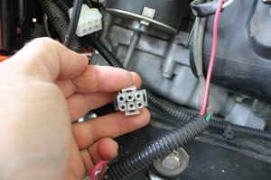
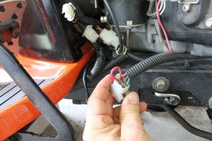
Notice my 6-way female end has yellow paint from the factory, if yours doesn’t, then match wire color to wire color. Top row left to right, black-red-grey, the opposite end should match when plugged in,

113.JPG

116.JPG

26) The charge/ stator connector is a 6-way also, but has only 4 prongs used, 2 are empty (no wires), match them up and connect,

117.JPG

118.JPG

119.JPG

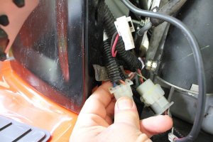
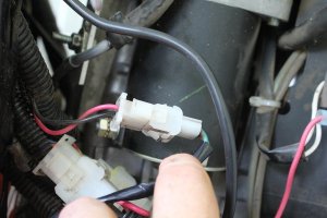
27) The PTO connector, 2-way, the only option left,

120.JPG

121.JPG

122.JPG

Stage-6, Coninued on the next reply,
 
Stage-6, Continued...

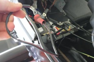
28) The starter power wire, 7/16” end wrench, don’t tighten too much, snug it sufficient so it doesn’t break loose by hand.

123.JPG

124.JPG

125.JPG

126.JPG

Stage-6, Coninued on the next reply,
 
Stage-6, Continued...

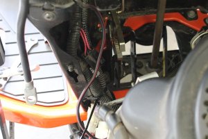
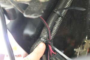
29) To prevent vibration damage to wires, secure wires with zip ties, Cut the zip tie ends to clean it up, keep wires from rubbing on metal edges and components,

127.JPG

128.JPG

129.JPG

130.JPG

131.JPG

132.JPG

133.JPG

134.JPG

136.JPG


This is the one way plastic anchor attached to the main harness, if it’s still good, place it here, (if its bad, don’t sweat it, the zip ties will do fine)

135.JPG

Center console electrics are done.

Stage-6, Coninued on the next reply,
 
Last edited:
Stage-6, Continued..

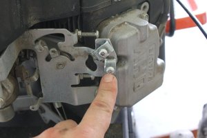
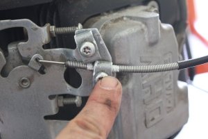
30) With a Torx 25, connect the throttle cable, bottom place on control plate,

137.JPG

The throttle,

138.JPG

Throttle back side, throttle cable secured at the throttle,

139.JPG

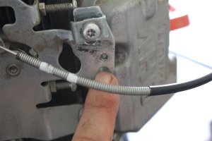
The throttle wrapping around the motor and set in metal securing tab,

140.JPG

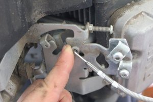
Attaches here, with a little pulled forward slack insert the cable end. Careful, don’t bend a kink in the wire.

141.JPG

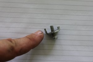
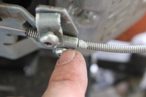
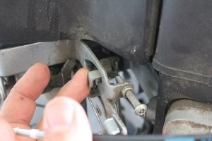
This is the lock, (longer prong)

143.JPG

The lock inserts here,

144.JPG

Remember the paint/ sharpie marks? Line them up and tighten in place.

145.JPG

Stage-6, Coninued on the next reply,
 
Stage-6, Continued...

31) Function check on the throttle, all the way forward and backward, with the lines lined up, should be no adjustment needed, and the cable function as smooth as before taking it off, the cable should not slip out of its lock as verified by your marks. (the idea is the metal outer shell is locked into place but the thin cable is free to move with the control lever)

Throttle lever pushed all the way forward (high speed), should rest against the bolt set limiter, and check your mark,

146.JPG

147.JPG

148.JPG

Throttle lever pulled all the way back (slow speed, idle), check mark, The bottom lock screw is the idle limit that was set by the factory and is less important than the upper limit, this is why I focused on the top.

(The top controls the limits that keep your engine from going “POP”! That would be bad, the lower limit actually has a lot of lever play as set by factory, as the reasoning goes, if the top lines up proper, the bottom is automatically good).


149.JPG

150.JPG

151.JPG

If your throttle control is smooth, throttle cable has proper limits on movement, and the marks haven’t moved, your done re-setting the throttle cable. You should not need to do any adjusting, all should still be at the factory settings. Now for the choke if yours is equipped.

32) Reconnect the choke cable.

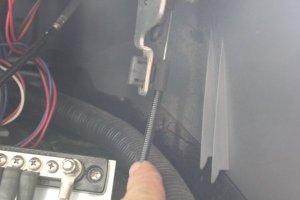
The choke cable starts here on the right, inside, center console,

152.JPG

153.JPG

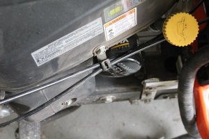
The wire is routed here in the center, on mine. Yours might be to the right of your throttle cable, either will work fine, the route should allow the cable to not bind. The cable will fit in between the battery tray and the metal support,

154.JPG

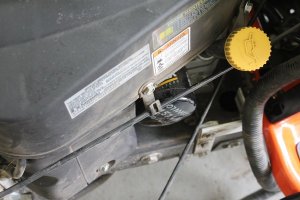
Route the cable on the outside of the oil dip stick tube and set inside metal support tab on top of the throttle cable, bend tab in to hold them there, it doesn’t need to be tight, a little loose here is good,

155.JPG

Stage-6, Coninued on the next reply,


Stage-6, Continued...

Go ahead and bring the choke control in as needed to insert the wire, (careful not to bend a kink in the wire),

156.JPG

157.JPG

Go ahead and lock down the chock cable in the same manner as the throttle cable in accordance to your paint marks, with the plate cable lock,

159.JPG

33) Function check the choke cable,

Choke pulled out, (choke on), check the mark,

159.JPG

Choke pushed in, (choke off), check the mark,

160.JPG

If your choke cable control is smooth, choke cable has proper limits on movement, and the marks haven’t moved, your done re-setting the the choke cable. You should not need to do any adjusting, all should function as factory set.

If both the throttle cable and the choke cable are visually and actively verified locked down, by your function check, done. If something went wrong, don’t panic, make sure you followed the steps, make sure the marks are lined up, and if you need more assistance, we can adjust the throttle and choke by other means.

Engine control install, done.

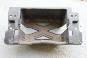
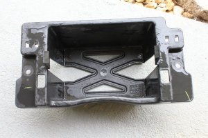
34) Battery tray install, (as a precaution, make sure this is cleaned well with soap and water, just in case the battery spilled acid, always good to start fresh here,

161.JPG

After,

162.JPG

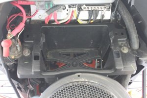
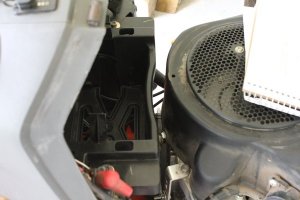
35) Install the battery tray with con-caved side toward the motor. 3/8” socket/ end wrench will work for these 2 bolts, snug them, don’t wrench them tight, the battery tray is plastic and can be cracked from over tight.

163.JPG

164.JPG

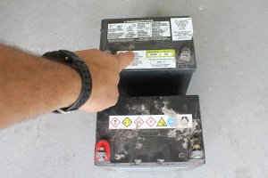
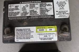
36) Install battery, Yours (most likely)

167.JPG

Mine,

168.JPG

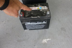
I’m pointing the difference out so as to not accidentally install the battery backwards, those are bad sparks,

Stage-6, Coninued on the next reply,
 
Stage-6, Continued..

Your battery positive post should be on the side your starter solenoid is on, or the right side, Also to further verify, the top post should have a raised “+” by the positive post,

172.JPG

And a raised “–“ by the negative post.

172.JPG

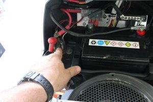
The thickest red wire is the positive cable and it’s connected to your starter solenoid here. Install your battery so that the “+” terminal is closest to the starter solenoid or on the right side.

174.JPG

The thick black wire bolted to your chassis is the negative or ground cable. The cable installed earlier here,

104.JPG

With your 7/16” end wrench, connect the negative cable, (after the positive cable),

Battery installed, done.

37) Install front hood and lights. With the hood on, connect the lights here, if used,

177.JPG

Your GT is almost done,

178.JPG

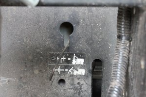
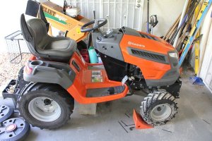
38) Check your freewheel rod for your transaxle, make sure its out, or disengaged as a precaution.

5.JPG

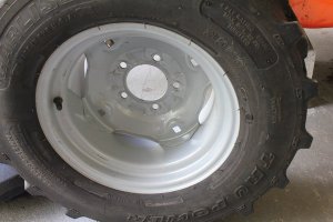
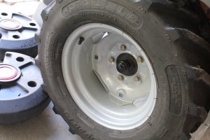
Install your rear wheels. The lugs should be installed by hand to protect against cross-threading. Don’t tighten yet, but have them snug.

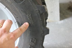
If you have lugs like mine or your tires are “directional” (as verified by an arrow on the side of the tire) make sure your arrow is pointing in the forward direction of travel. I think turfs are uni-directional, but make sure.

179.JPG

180.JPG

181.JPG

Our wheel bolt torque specification is 65 foot lbs, (same as John Deere, with same wheel bolt size and wheel size)

I believe a properly seated wheel is important, especially if using your GT for ground engagement work.

Referring to the “star” pattern, while looking at your wheel from the side, count the bolt holes in a clock-wise pattern from the top all the way around, assigning them a number, in order, 1-2-3-4-5.

The star pattern for tightening wheel bolts as a guide, are as follows in the same order but now tighten 1, then 3, then 5, then 2, and last 4. It is like drawing a five pointed star. When loosening wheel bolts that are torqued the same practice is a good one also, especially with aluminum wheels.

With the wheel secured by a helper, wheel chocks, your feet, etc.

182.JPG

Stage-6, Coninued on the next reply,
 
Stage-6, Continued...

(This worked for me keeping the wheel secured while use both hands to torque, it’s still a 1/2” off the ground)
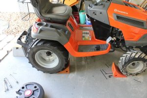
184.JPG

If following the 60% rule, and with a 5/8” socket and extension,
Set your torque wrench to 40 foot lbs and tighten all bolts in a star pattern to 40’lbs first.

Second, Set your torque wrench to 65 foot lbs and in a star pattern tighten the bolts to 65’lbs and done.


The method I used, set torque wrench to 65 foot lbs, tighten all bolts in a star pattern to 65’lbs, then take a socket wrench and back off each bolt in a star pattern approx ¼ to ½ a turn, just enough to break the bolt loose again, and then take my torque wrench that is still set to 65 foot lbs and in a star pattern, tighten them again to 65’lbs.

The principle behind either method is to create an even clamping force between the wheel and hub, either one can be bent or warped if the clamping was too tight on one bolt and not on the other bolts.

The above two methods help prevent this, either is fine.

For those that want to chime in that 65 foot lbs is not enough torque to be concerned about, your probably right, but then the purpose of this guide is for those that don’t have much skill as well as those that do. A good habit and mindset with wheels (think the car too) can’t be bad, plus it’s easy, so why not?

A maintenance tip for those using a clicker type torque wrench. To preserve the spring tension during none use/ storage, back the torque off to either its “start” position, or “end” position, or the first torque setting while it’s stored. If your first torque number is 25 then store it here, but don’t go below this.

If your wrench is old and you are questioning its accuracy, (at these low settings, precision accuracy is not needed), machine shops are the most common place to calibrate them.

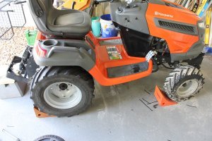
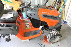
Your tractor is ready to put on the ground.

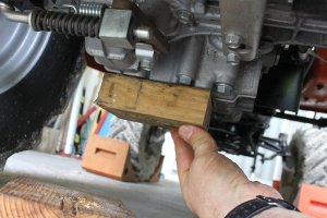
39) Get your floor jack, with your block of wood,
7.JPG

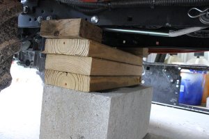
lift your tractor off its temporary support base, remove the base,
9.JPG

Gently lower your GT to the ground,

183.JPG

40) Put approximately 1 gallon of fuel in your fuel tank for the last tests. (if you have to go back into it, you only have a gallon at risk)

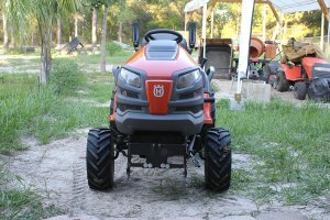
Remove your wheel chocks, and push your GT to a safe location to get prepared for a function check. For me it was just a few feet back on the grass,
185.JPG

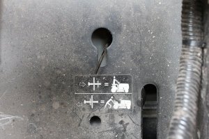
41) Engage your transaxle by pushing the transaxle freewheel rod back in.
4.JPG

Tip- Quickly re-look at your GT, look for anything that might get hung up in the drive belt,

42) Start your tractor, (it’s light right now, this is good) and perform a function check on your transaxle in reverse, and forward. Keep doing this until the response is immediate (should respond right away, if the steps were followed).

After a few minutes of this turn the tractor off, check everything that moves, belts are in their keepers, and try and look at the fluid level in the transaxle reservoir, a real pain I know, but take the time to make sure that fluid is in there a couple notches at least.

Continue to verify your K66 is free of leaks, paying attention to drips on the right side under the hydro chamber side. The right side is where the drips will show up if the fill tube to the reservoir bottle is leaking. Leaks are bad, but if you were to have any leaks, this is the last best time to find them.

43) If your GT is healthy, (passing first of three important inspections) start your GT and drive around for at least 15 minutes, getting your transaxle up to operating temperature, then shut it down, let the transaxle go through a cool down cycle.

Once your K66 cools down, this is relative to the outside conditions and season, but it should be cool to the touch, then inspect for leaks and fluid in the reservoir bottle again. If it passes here, Stage 6 is complete. The GT is happy, and you the owner should be proud of the work you just completed.

Stage 7 will be the installation of your mowing deck without fighting with belt tension, anti-sway bar installation, and preserving all your deck settings.

I found the picture of the clock for the specific hrs of this job...
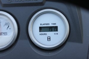
191.JPG

 
Back
Top