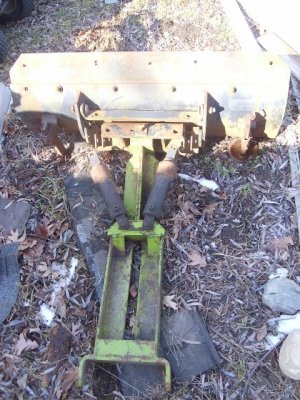
Agricat crawler model-F

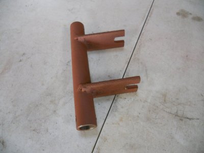
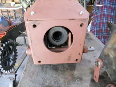
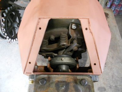
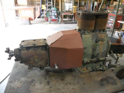
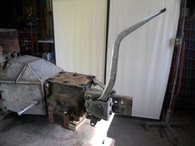
I have mounted the shifter on the back of the transmission and I have also made up the shaft that goes thru the bellhousing that will operate the throwout bearing.
DSCN1679.JPG


The shifter can be mounted in three different positions. It is in the farthest forward position now. I won't make up the shifter rods until I know which of the three positions the shifter will be in.
I'm waiting for a Farmall Cub throwout bearing to arrive so I can't go any farther on the transmission.

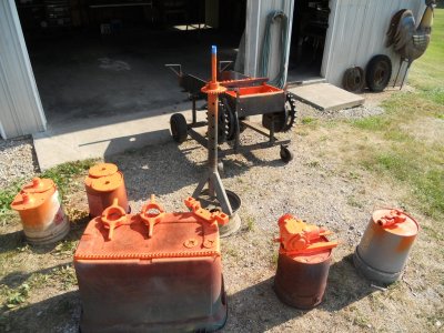
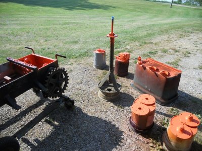
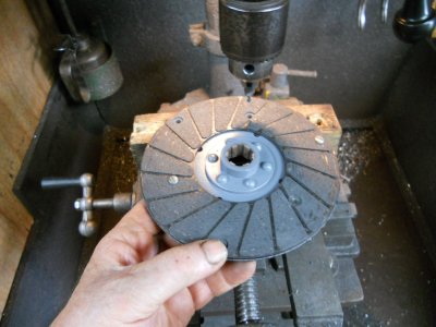
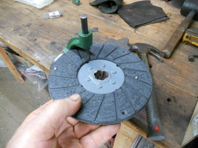
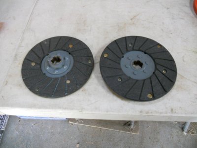
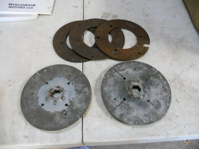
While I'm waiting on parts, I have gotten out the parts for the two drive clutches on the rear axle. The clutch pads are removed from the clutch discs and the discs plates have been sandblasted.
I got on line and found new clutch pads that are the same size as what is on this crawler. They are for a bush hog mower so I have ordered 4-new clutch pads and the rivets to mount them.
DSCN1660.JPG


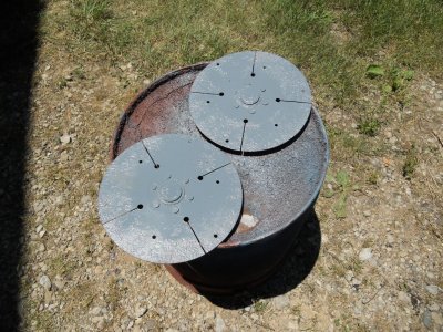
The clutch disc plates have been sandblasted, primed and painted gray.
DSCN1665.JPG


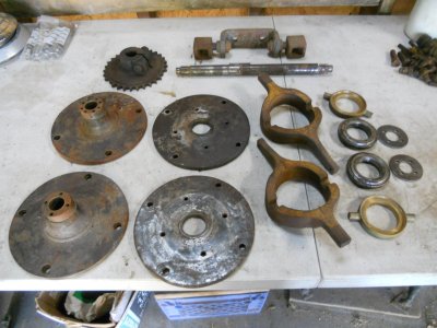
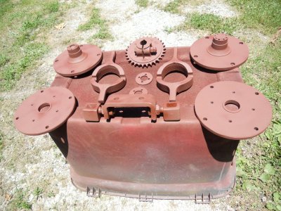
These are the rest of the parts to complete the rear axle.
DSCN1663.JPG


These parts have been sandblasted and primed.
DSCN1668.JPG


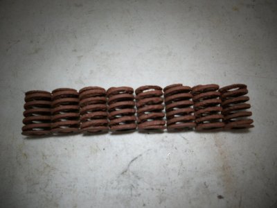
These are the original springs for the drive clutches. They all have become rusted, some rather badly. After cleaning them up and priming them, I have decided that I'm not going to use them.
Luckily, these are the same size as the springs that are used on stamping dies so I have ordered 8-new ones and have thrown the old ones away.
DSCN1670.JPG


So now I'm waiting on even more parts to arrive. Meanwhile, I can still set up the rear drive system.
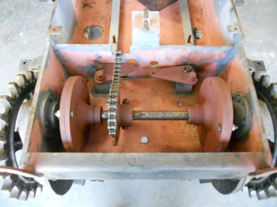
I've mounted the rear chain sprocket on the axle shaft and bolted it in place.
DSCN1672.JPG


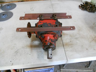
I never had the correct engine or transmission for this little crawler but I did get this right angle drive gearbox with it.
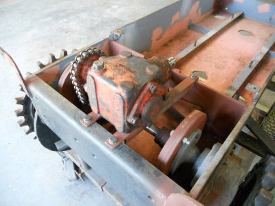
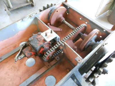
The gearbox is mounted with 4-bolts on the bottom of it. I have made up two angle iron brackets and bolted them to the bottom of the gearbox.
DSCN1676.JPG


This way I can mount it in the crawler from above instead of having to bolt in place from under the crawler.
The gearbox is set in place and ready to have the mounting holes drilled and tapped thru the holes in the angle iron brackets.
DSCN1677.JPG
 
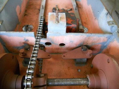
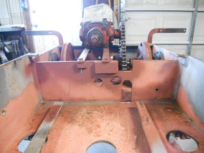
This morning when I went out to the garage and looked at the crawler, I realised right away that having the right angle gearbox down in front of the rear axle is not going to work at all.
It is sitting right in front of the two holes in the cross plate for the control rods going to the steering clutch linkage arms.

DSCN1680.JPG


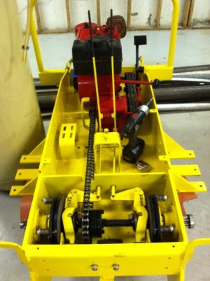
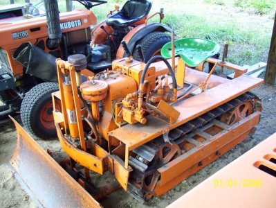
This is a photo of how the factory drive system looked. The transmission sets crosswise right behind the engine with a long chain going back to the rear axle. That leaves plenty of room for the two control levers for the steering clutches.

1IMG_0257.jpg


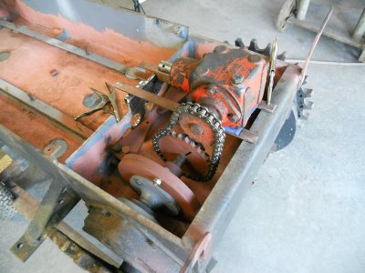
So I have made new mounting brackets for the gearbox and I'm moving it so it sits over the rear axle. I'm getting it all lined up here.

DSCN1694.JPG


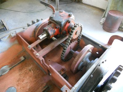
The gearbox is bolted in place.

DSCN1695.JPG

DSCN1696.JPG


Now the area is clear in front of the holes for the steering clutch arms.

DSCN1698.JPG


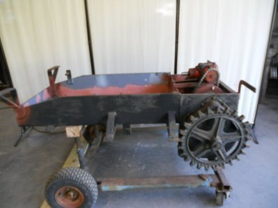
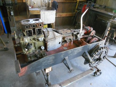
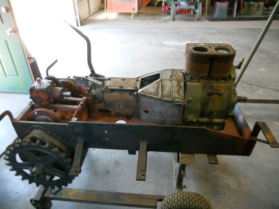
Here's a side view of the crawler frame.
With the gearbox sitting above the rear axle, This will also raise the engine and transmission up higher and that will leave room underneath it for the steering clutch linkage.

DSCN1697.JPG


The original engine sat down low inside the crawler frame. The top of the engine was lower than the seat.
I like the idea of having the engine sitting up higher in the frame.

GrampsMiniDozer184.jpg


.................. On a different subject ....................

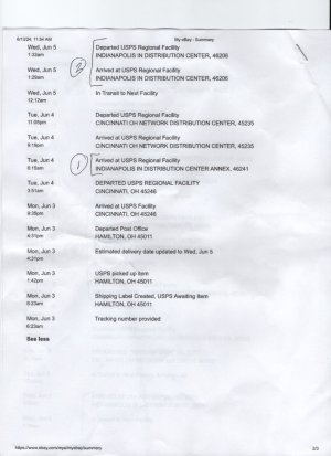
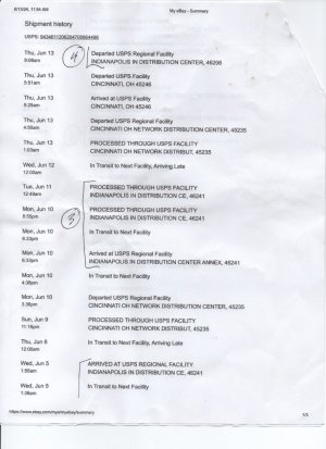
The Farmall Cub throwout bearing was sent out on June 3ed. I checked the tracking today and it shows that it has been shipped back and forth between Cincinnati and Indianapolis 4 times.

When a package reaches Indianapolis, I usually get it delivered the next day.

The tracking shows that the package left Indianapolis at 8 AM this morning ( the 13th ).
I went down to the Post Office this afternoon and they said that there is a problem with the automatic scanning system and that the package had gone back to Cincinnati for the 5th time.
They are going to send Cincinnati an email and see if this problem can be straightened out.

Here is a copy of the tracking.

Scan_20240613  (1).jpg

Scan_20240613 (2).jpg
 
This morning when I went out to the garage and looked at the crawler, I realised right away that having the right angle gearbox down in front of the rear axle is not going to work at all.
It is sitting right in front of the two holes in the cross plate for the control rods going to the steering clutch linkage arms.

View attachment 82452


This is a photo of how the factory drive system looked. The transmission sets crosswise right behind the engine with a long chain going back to the rear axle. That leaves plenty of room for the two control levers for the steering clutches.

View attachment 82453


So I have made new mounting brackets for the gearbox and I'm moving it so it sits over the rear axle. I'm getting it all lined up here.

View attachment 82454


The gearbox is bolted in place.

View attachment 82455

View attachment 82456


Now the area is clear in front of the holes for the steering clutch arms.

View attachment 82457


Here's a side view of the crawler frame.
With the gearbox sitting above the rear axle, This will also raise the engine and transmission up higher and that will leave room underneath it for the steering clutch linkage.

View attachment 82458


The original engine sat down low inside the crawler frame. The top of the engine was lower than the seat.
I like the idea of having the engine sitting up higher in the frame.

View attachment 82461


.................. On a different subject ....................

The Farmall Cub throwout bearing was sent out on June 3ed. I checked the tracking today and it shows that it has been shipped back and forth between Cincinnati and Indianapolis 4 times.

When a package reaches Indianapolis, I usually get it delivered the next day.

The tracking shows that the package left Indianapolis at 8 AM this morning ( the 13th ).
I went down to the Post Office this afternoon and they said that there is a problem with the automatic scanning system and that the package had gone back to Cincinnati for the 5th time.
They are going to send Cincinnati an email and see if this problem can be straightened out.

Here is a copy of the tracking.

View attachment 82459

View attachment 82460
Sounds like you need to head up 65 and pick that up yourself. Or is cinncy closer?
 
I have made up the engine mounts and it is set down into the frame.

DSCN1699.JPG

DSCN1700.JPG


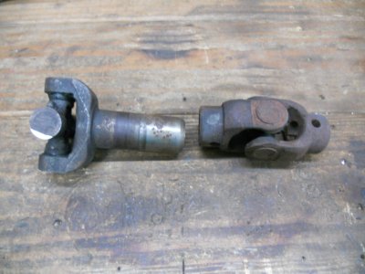
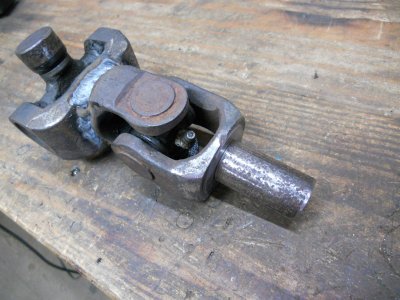
These are the two universal joints that I'm going to use to make the driveshaft.

DSCN1701.JPG


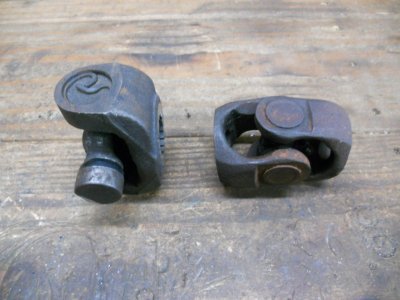
The ends are cut off both pieces.

DSCN1702.JPG


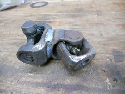
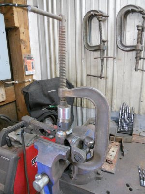
I turned down a pin with the two different diameters of the center holes in each part. This holds the two parts on center to each other and they are welded together.

DSCN1706.JPG


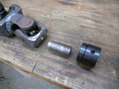
I bought a pulley hub with the keyway already in it that fits onto the input shaft of the right angle gearbox. Then I made up another pin with the two different diameters on it.

DSCN1708.JPG


This pin fits into the center hole on the U-joint.

DSCN1709.JPG


The hub is slid onto the pin and it is clamped together and welded.
DSCN1711.JPG


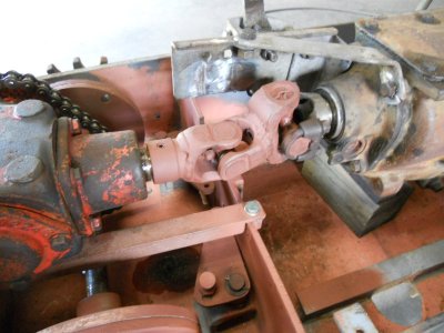
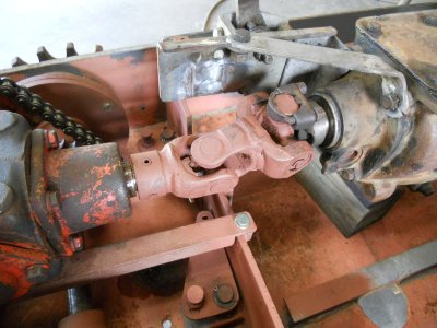
Here is the finished driveshaft.

DSCN1712.JPG

DSCN1713.JPG
 
I have made up the engine mounts and it is set down into the frame.

View attachment 82507

View attachment 82508


These are the two universal joints that I'm going to use to make the driveshaft.

View attachment 82509


The ends are cut off both pieces.

View attachment 82510


I turned down a pin with the two different diameters of the center holes in each part. This holds the two parts on center to each other and they are welded together.

View attachment 82511


I bought a pulley hub with the keyway already in it that fits onto the input shaft of the right angle gearbox. Then I made up another pin with the two different diameters on it.

View attachment 82512


This pin fits into the center hole on the U-joint.

View attachment 82513


The hub is slid onto the pin and it is clamped together and welded.
View attachment 82514


Here is the finished driveshaft.

View attachment 82515

View attachment 82516
Not nit picking but wondering. Your drive shaft would be the center two yokes that are welded at 90* to each other. I thought they needed to be parallel to each other not perpendicular. Just asking.
 
Not nit picking but wondering. Your drive shaft would be the center two yokes that are welded at 90* to each other. I thought they needed to be parallel to each other not perpendicular. Just asking.

You are absolutely correct. On a regular driveshaft, the yokes need to be lined up with each other. This is called phasing or timing the driveshaft, and it can help offset the acceleration and deceleration of one joint with the other joint. This can result in equal RPM from the transmission's output to the driven axle.
However, on a driveshaft this short that will not be rotating very fast at all, it doesn't matter as long as the U-joints are still lined up with each other.
I set them at 90 degrees because it gave me more clearance to get a good weld on them.
Okay. Thanks.
 
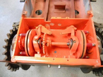
I should have the rest of the parts for putting the steering clutches together by tomorrow so today I finished cleaning up the other parts and got them all painted.

DSCN1715.JPG

DSCN1716.JPG


While doing that, I realised that I'm missing four angle brackets and brake pads.

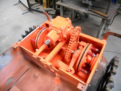
In this photo of a crawler being put together by someone else, you can see the 3/8 thick by 2 inch wide brackets with brake pads fastened onto them.
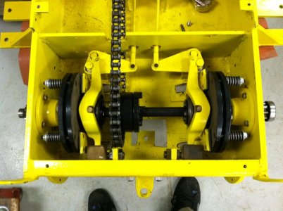
There are two brackets sticking up from the floor on the inside of the round plates that clamp together with the clutch disc in between them.
When the inside plate is pulled in to release the clutch disc, it is pulled up against the two brackets on that side to stop the round plate from rotating while the other side continues to rotate and turn the crawler.

I have ordered some brake pad material from Mc Master-carr so I can make up those brackets.
1IMG_0256.jpg
 
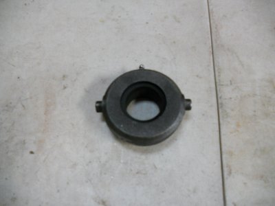
Here is the Farmall Cub throwout bearing.

DSCN1727.JPG


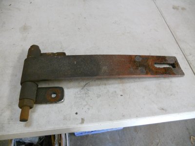
I have made up the bracket for operating the throwout bearing.

DSCN1723.JPG


Here is how it looks mounted on the bracket inside the bellhousing.

DSCN1726.JPG


And with the transmission in place.

DSCN1724.JPG


The welds have been ground down on the bellhousing and it is primed.

DSCN1725.JPG
 
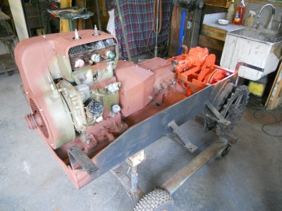
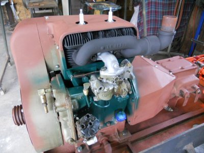
The engine is rebuilt and set back in the frame.

DSCN1728.JPG

DSCN1729.JPG


The engine will be painted dark hunter green and the area behind the exhaust manifold and the carburetor has been painted so I could bolt those parts on.

DSCN1731.JPG

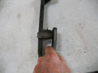
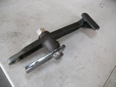
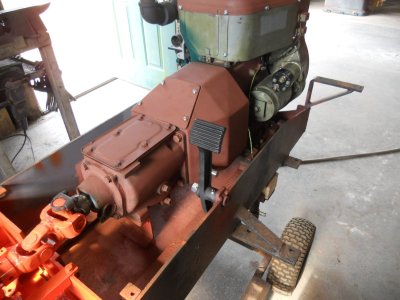
This is the clutch pedal and it's mount.

DSCN1732.JPG


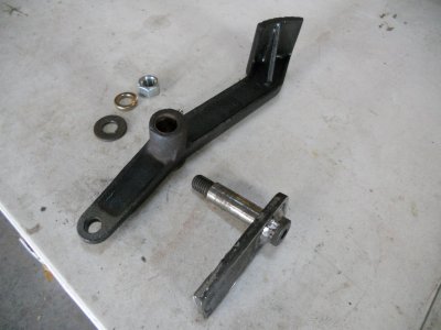
The pivot shaft is only long enough to go thru the bore in the pedal and there isn't any provision for putting a cotter pin in or a bolt and washer in the end of the shaft so I'm not sure how the pedal stayed on the shaft ?

DSCN1734.JPG


At any rate, the shaft is pitted from rust and it is lose in the mounting bracket so I have removed it from the bracket and welded in a shoulder bolt to replace it.

DSCN1736.JPG


This gives the pedal a hardened shaft to pivot on with a nut and washer on the end to keep it in place.

DSCN1738.JPG


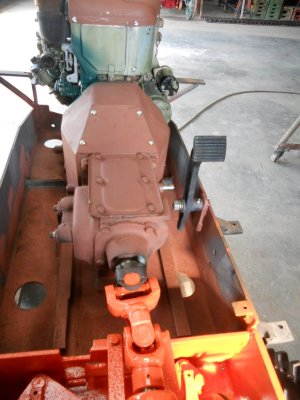
The clutch pedal is mounted onto the frame.

DSCN1740.JPG

DSCN1741.JPG
 
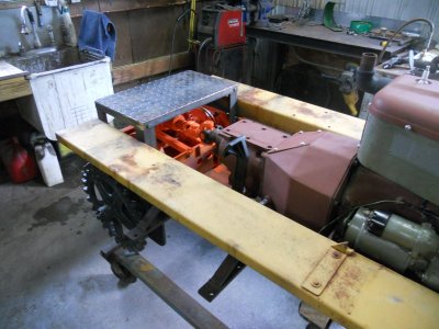
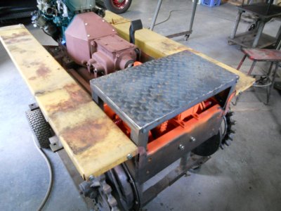
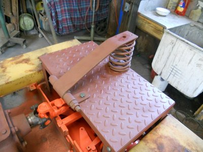
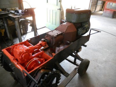
I've built a platform over the rear of the crawler using diamond plate steel.
This platform is easily removable by unfastening 4-bolts.
DSCN1743.JPG

DSCN1744.JPG


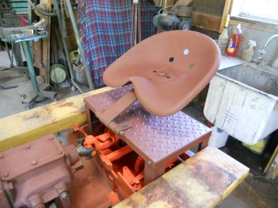
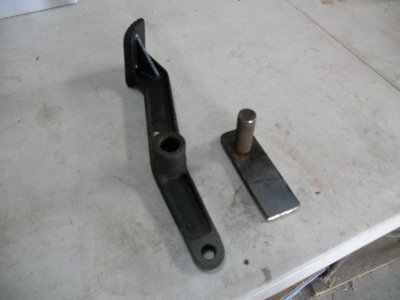
I'm going to use this seat mounting bracket that was on that homemade tractor that I put the Ford model-A engine in.
DSCN1745.JPG


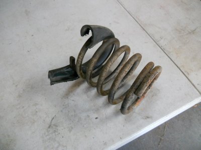
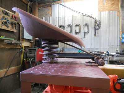
I have a pair of old light duty helper springs that are designed to bolt onto the rear axle of a small car or trailer.
I set one of them on the floor and stood on it and I think it has just the right amount of tension for the seat spring.

DSCN1747.JPG


Here is the finished seat mounting bracket.

DSCN1748.JPG


And with the seat mounted.

DSCN1749.JPG

DSCN1751.JPG


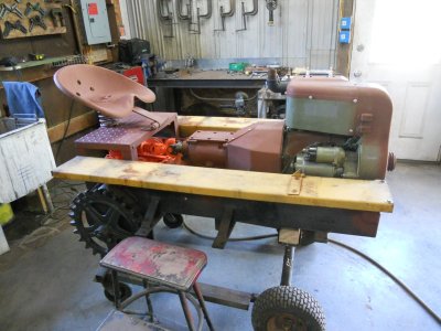
How it looks in relation to the rest of the crawler.

DSCN1752.JPG
 
I got up on the crawler and sat down in the seat and that spring is just right. It has a nice cushioned bounce to it.

The seat on my JD tractor that I mow with has two little 1 inch long springs on it and it is a hard ride going over some of the rougher areas of my lawn.
I should take the other helper spring and somehow fit it onto that seat on the mower.
 
Back
Top