You are using an out of date browser. It may not display this or other websites correctly.
You should upgrade or use an alternative browser.
You should upgrade or use an alternative browser.
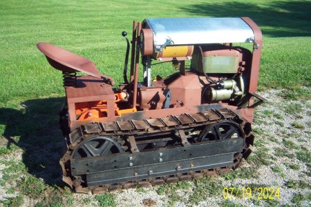
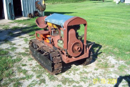
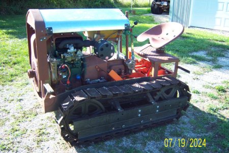
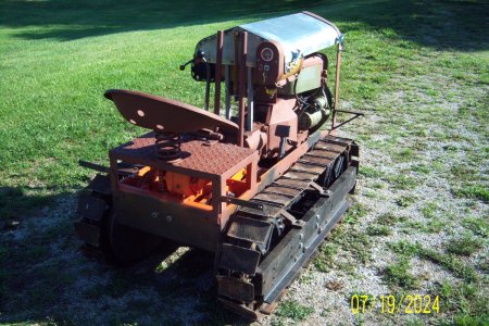
Agricat crawler model-F
- Thread starter jdcrawler
- Start date
Lowering the crawler down onto the tracks.
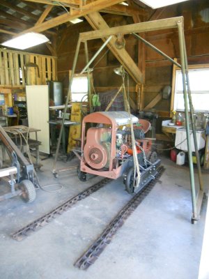
Sitting on the tracks.
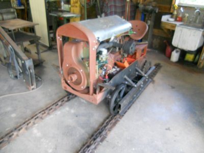
The front end of this track is pulled up and fastened to back end of the track.
Then the adjusting nut is screwed out to tension the track.
Pushing down on the center of the top track, it will go down about 1-1/2 inch.
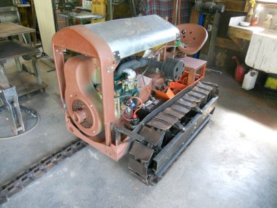
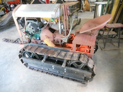
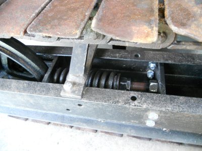
Here is the track tensioning assembly.
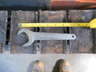
A long time ago, I had picked up this short 1-1/2 inch wrench.
It has been hanging on my tool room wall for ages and I have never used it.
It works perfect for adjusting the nuts on the track tensioner.
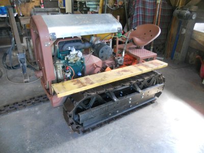
This gives you an idea of how the crawler will look with the fenders on.

Sitting on the tracks.

The front end of this track is pulled up and fastened to back end of the track.
Then the adjusting nut is screwed out to tension the track.
Pushing down on the center of the top track, it will go down about 1-1/2 inch.


Here is the track tensioning assembly.

A long time ago, I had picked up this short 1-1/2 inch wrench.
It has been hanging on my tool room wall for ages and I have never used it.
It works perfect for adjusting the nuts on the track tensioner.

This gives you an idea of how the crawler will look with the fenders on.

I got in too much of a rush once I had the tracks on and I forgot to make the dirt guard plates that fit over the center of the track rail before I let the crawler down to take it for a ride.
So I decided to jack up one side at a time so it's up where I can work on it easier.
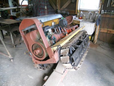
I'm making the dirt guard plate out of 1/16 inch thick stainless steel.
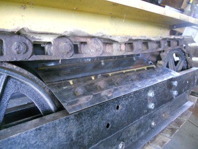
Here is the finished guard plate on this side.
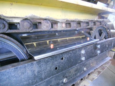
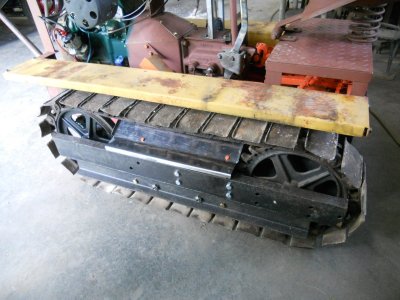
And on the other side.
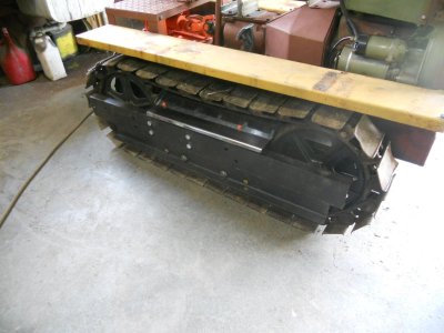
So I decided to jack up one side at a time so it's up where I can work on it easier.

I'm making the dirt guard plate out of 1/16 inch thick stainless steel.

Here is the finished guard plate on this side.


And on the other side.

Using my plasma cutter, I have trimmed the back edge off of both of the upright posts.
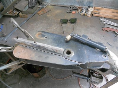
Then I put them up on the mill to start machining the rough edges down.
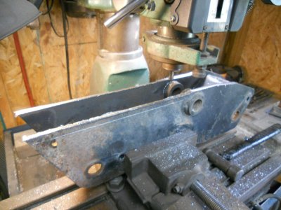
Here is the finished machined part.
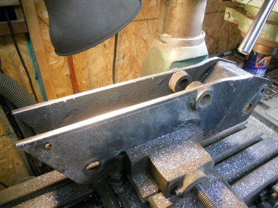
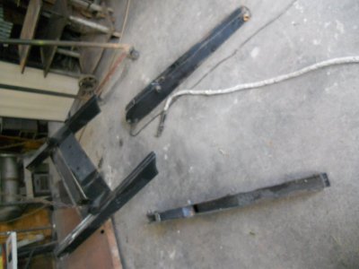
Next is to cut the upper back part of the lift arms off.
These are put on the saw to cut the ends off them.
Here I'm lining up the angled line where this one is to be cut.
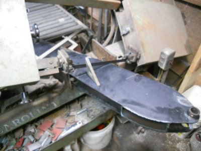
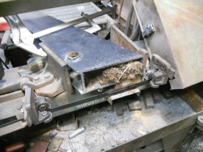
Both of them had critter nest in them.
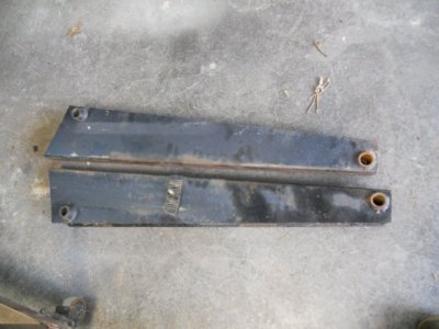
These are the two shortened upper back lift arms.
The ends that were cut off have the back edge and the cylinder mounting brackets cut off them.
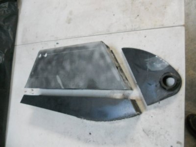
These are the parts to make up the two new upright post.
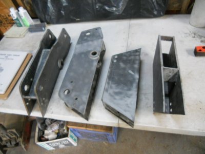
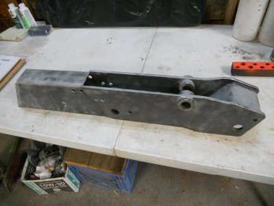
The two parts for each side will fit together like this.
This is the backside of the upright post.

Then I put them up on the mill to start machining the rough edges down.

Here is the finished machined part.

Next is to cut the upper back part of the lift arms off.

These are put on the saw to cut the ends off them.
Here I'm lining up the angled line where this one is to be cut.

Both of them had critter nest in them.

These are the two shortened upper back lift arms.

The ends that were cut off have the back edge and the cylinder mounting brackets cut off them.

These are the parts to make up the two new upright post.

The two parts for each side will fit together like this.
This is the backside of the upright post.

Here's one of the upright post welded together.
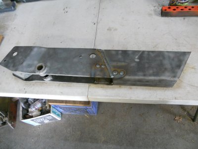
Both of them with the welds ground down.
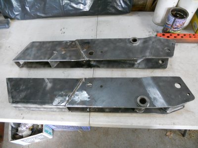
This is the front side.
The end of the upper lift arm will fit into the gap at the top ( far right holes ) and the end of the hydraulic cylinder will fit into the gap between the two holes in the center.
I have ordered some 2-1/2 inch wide by 3/16 inch thick flat steel to fill in the gaps in the part that I've added on but it won't most likely be here until Monday.
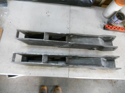
This is the back side.
The two holes towards the right end will hold one end of a support rod.
The other end of this rod will fasten down to the back of the track frame rail.
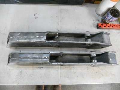

Both of them with the welds ground down.

This is the front side.
The end of the upper lift arm will fit into the gap at the top ( far right holes ) and the end of the hydraulic cylinder will fit into the gap between the two holes in the center.
I have ordered some 2-1/2 inch wide by 3/16 inch thick flat steel to fill in the gaps in the part that I've added on but it won't most likely be here until Monday.

This is the back side.
The two holes towards the right end will hold one end of a support rod.
The other end of this rod will fasten down to the back of the track frame rail.

The mounting plate for the upright post is made out of 1/4 inch thick steel.
Here it is clamped to the track side rail to start drilling the holes into the side rail.
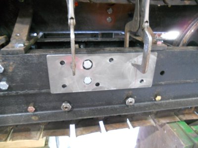
The mounting plate will be held on by three 1/2 inch studs coming thru from the inside and two 1/2 inch bolts threaded in from this side.
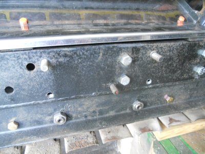
The mounting plate is bolted to the side rail and the upright post is clamped in place.
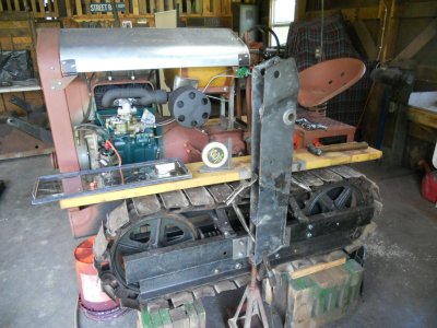
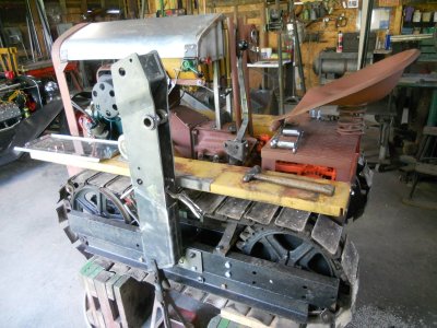
The upright post is welded to the mounting plate.
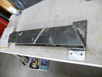
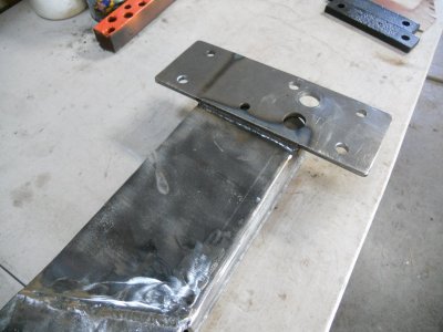
The post is mounted back onto the crawler.
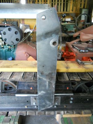
There is about 1/4 inch clearance between the side of the post and the fender.
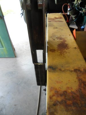
Here it is clamped to the track side rail to start drilling the holes into the side rail.

The mounting plate will be held on by three 1/2 inch studs coming thru from the inside and two 1/2 inch bolts threaded in from this side.

The mounting plate is bolted to the side rail and the upright post is clamped in place.


The upright post is welded to the mounting plate.


The post is mounted back onto the crawler.

There is about 1/4 inch clearance between the side of the post and the fender.

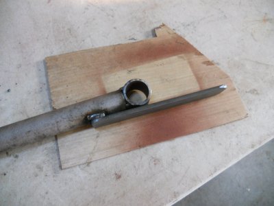
A piece of round tube is welded to the end of a piece of 1 inch solid bar.
Then a piece of 3/16 inch thick strap steel is tack welded to it.
The strap steel is heated up and formed around the piece of tube.
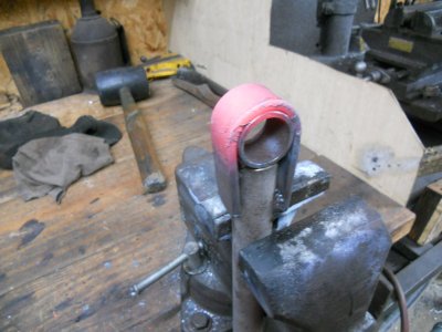
The ends of the strap steel are welded to the 1 inch bar and a piece of 3/8 inch thick steel is welded to the other end.
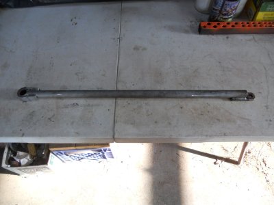
This is the rear support rod for the upright post.
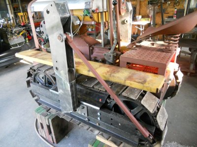
Then a piece of 3/16 inch thick strap steel is tack welded to it.

The strap steel is heated up and formed around the piece of tube.

The ends of the strap steel are welded to the 1 inch bar and a piece of 3/8 inch thick steel is welded to the other end.

This is the rear support rod for the upright post.

The steel strap arrived two days early so I was able to finish the upright post today.
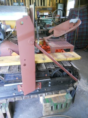
Here is the front of the posts with the big open gaps at the bottom ( left end ).
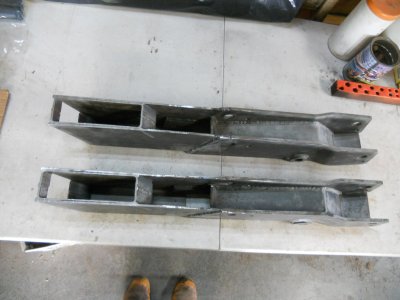
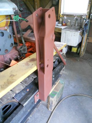
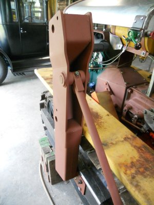
And the finished post with the gaps filled in.
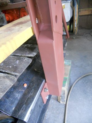
This is the back of the posts with an open gap in the center.
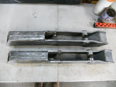
The finished post.
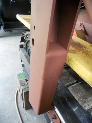
How it looks on the crawler.
Here is the front of the posts with the big open gaps at the bottom ( left end ).

And the finished post with the gaps filled in.

This is the back of the posts with an open gap in the center.

The finished post.

How it looks on the crawler.


Reminder of how the front end loader looked when I got it.
The loader arms are angled between the upper arms and the lower arms.
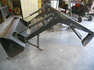
I had expected this angle between the upper and lower arms to be maintained when I mounted it on my crawler, the same as it would be on a garden tractor loader.
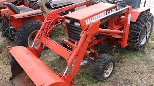
So I was surprised when I mounted the upper arms and the hydraulic cylinders and saw that the arms are angled down toward the floor.
On the original tractor, the upright post must of been mounted so they laid back at and angle instead of standing straight up.
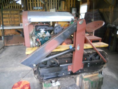
Then I got to thinking about how loaders are mounted on crawlers.
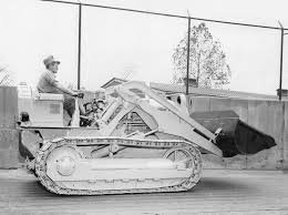
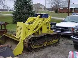
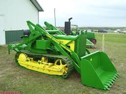
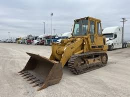
Most of them don't have the sharp angle in the loader arms.
The reason for this is that a crawler is capable of putting much more pressure on the loader arms than a tractor can and that point where the upper and lower arms came together at an angle would be a weak spot that could easily be bent farther.
These loader arms are strong enough that they would never bend with the amount of pressure that this little crawler will be able to produce, even if they were bent at the original angle.
Still, having them straighter certainly isn't going to hurt anything.
The question now is, how much lift height will the bucket have ?
So I raised the arm up as high as it will go.
With the crawler up on the blocks, the surface of the bottom of the upside down bucket is 1/2 inch higher than the blocks.
The center of the pin for the cylinder is 4 foot 11 inches off the bucket.
With the arms extended out to reach the bucket, the bottom of the bucket will be over 6 foot off the ground.
Looks like everything is going to work out just fine.
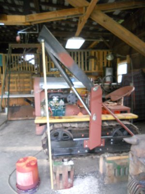
The loader arms are angled between the upper arms and the lower arms.

I had expected this angle between the upper and lower arms to be maintained when I mounted it on my crawler, the same as it would be on a garden tractor loader.

So I was surprised when I mounted the upper arms and the hydraulic cylinders and saw that the arms are angled down toward the floor.
On the original tractor, the upright post must of been mounted so they laid back at and angle instead of standing straight up.

Then I got to thinking about how loaders are mounted on crawlers.
Most of them don't have the sharp angle in the loader arms.
The reason for this is that a crawler is capable of putting much more pressure on the loader arms than a tractor can and that point where the upper and lower arms came together at an angle would be a weak spot that could easily be bent farther.


These loader arms are strong enough that they would never bend with the amount of pressure that this little crawler will be able to produce, even if they were bent at the original angle.
Still, having them straighter certainly isn't going to hurt anything.
The question now is, how much lift height will the bucket have ?
So I raised the arm up as high as it will go.
With the crawler up on the blocks, the surface of the bottom of the upside down bucket is 1/2 inch higher than the blocks.
The center of the pin for the cylinder is 4 foot 11 inches off the bucket.
With the arms extended out to reach the bucket, the bottom of the bucket will be over 6 foot off the ground.
Looks like everything is going to work out just fine.

Someone has tried to pull something with a couple of chain hooks attached to the top edge of the bucket and has bent that edge.
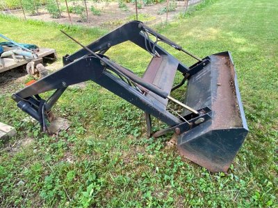
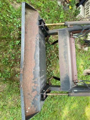
I've heated up that area and hammered down the two points that were pulled up by the chain hooks.
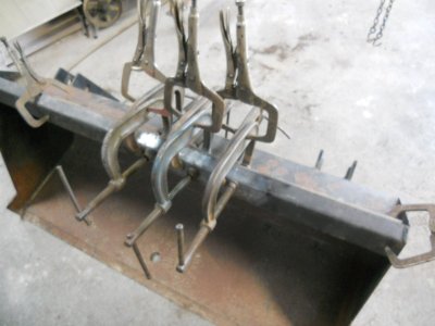
Then, with a square steel tube set behind, I've placed 6 C-clamps on it to try to pull the front edge back in place.
The pairs of clamps are held together with vice-grips to keep them from rotating when I tighten the screws down.
I tighten each screw a little at a time and keep going around the bucket doing that until the screws won't turn anymore.
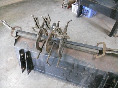
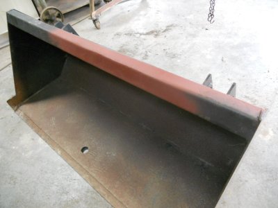
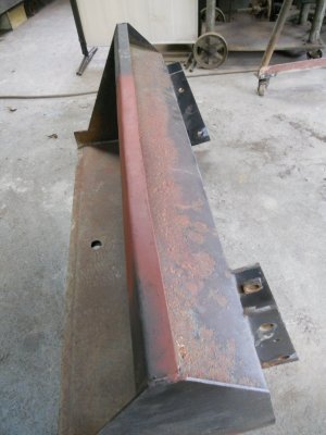
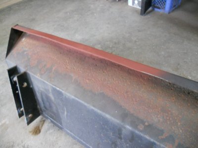
It isn't 100 percent perfect but it sure looks a lot better.


I've heated up that area and hammered down the two points that were pulled up by the chain hooks.
Then, with a square steel tube set behind, I've placed 6 C-clamps on it to try to pull the front edge back in place.
The pairs of clamps are held together with vice-grips to keep them from rotating when I tighten the screws down.
I tighten each screw a little at a time and keep going around the bucket doing that until the screws won't turn anymore.


It isn't 100 percent perfect but it sure looks a lot better.


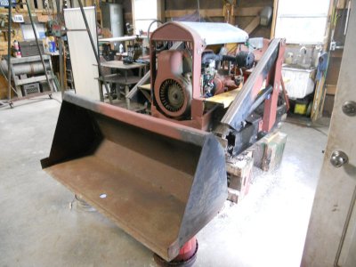
Positioning the bucket to where it will be in relation to the crawler.
This allows enough room so the bucket can be tilted all the way back without hitting the crawler.
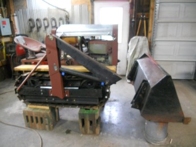
The bucket is 10 inches wider on each side then the outside of the tracks so the tracks will always be on cleared ground even when making gradual turns.
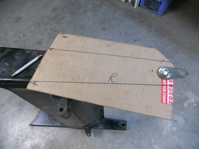
I put a 1 inch diameter hole in a piece of cardboard so it can fit onto the lower mounting pin on the bucket.
Then I cut the back of the cardboard off where it lines up with the end of the upper loader arm.
This is then transferred to the lower loader arm to mark it where it needs to be cut off.
I'll only be using about 16 inches of the lower loader arms.
This allows enough room so the bucket can be tilted all the way back without hitting the crawler.

The bucket is 10 inches wider on each side then the outside of the tracks so the tracks will always be on cleared ground even when making gradual turns.

I put a 1 inch diameter hole in a piece of cardboard so it can fit onto the lower mounting pin on the bucket.
Then I cut the back of the cardboard off where it lines up with the end of the upper loader arm.
This is then transferred to the lower loader arm to mark it where it needs to be cut off.
I'll only be using about 16 inches of the lower loader arms.

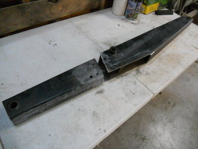
The front section of the loader arm is cut off and it is lined up with the rear section.
This is the outside of the arm and holes have been drilled into it for making pocket welds to a reinforcing steel plate that will be on the inside of the arm.
The upper part of the arm was much wider at this joint area so I have trimmed it back to line up with the surface of the front part of the arm.
The top edge section and two triangular pieces were cut out.
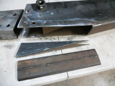
I'm lining the two pieces up for welding.
The two pieces are about 3/8 different in thickness.
With the surfaces on the the outside of the arm lined up flush with each other, there is a step between the surfaces on the inside of the arm.
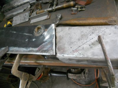
I have cut out this piece out of 1/8 inch thick steel plate.
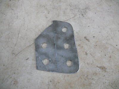
This fits into the gap between the two pieces. Half of it fitting inside the upper arm and the rest fitting on the outside of the lower arm and they are welded together.
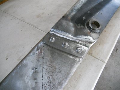
This is a view of that plate welded on the inside.
You can see the edge of the reinforcing plate that is welded inside the other side of the arm.
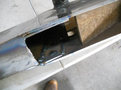
This is the outside surface with the welds all ground down.
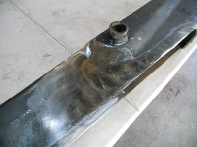
The cap is welded back onto the top edge and the arm is primed.
This is the inside surface.
I decided to leave the pocket welds showing on this side.
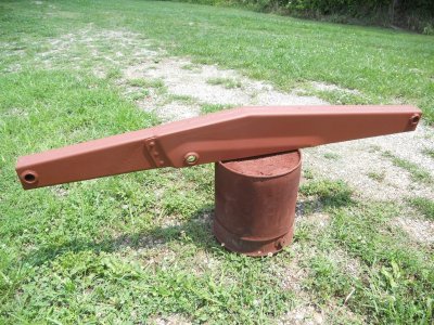
This is the outside.
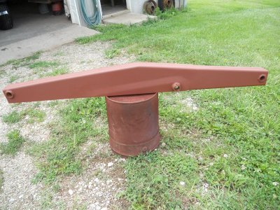
This is the outside of the arm and holes have been drilled into it for making pocket welds to a reinforcing steel plate that will be on the inside of the arm.

The upper part of the arm was much wider at this joint area so I have trimmed it back to line up with the surface of the front part of the arm.
The top edge section and two triangular pieces were cut out.

I'm lining the two pieces up for welding.
The two pieces are about 3/8 different in thickness.
With the surfaces on the the outside of the arm lined up flush with each other, there is a step between the surfaces on the inside of the arm.

I have cut out this piece out of 1/8 inch thick steel plate.

This fits into the gap between the two pieces. Half of it fitting inside the upper arm and the rest fitting on the outside of the lower arm and they are welded together.

This is a view of that plate welded on the inside.
You can see the edge of the reinforcing plate that is welded inside the other side of the arm.

This is the outside surface with the welds all ground down.

The cap is welded back onto the top edge and the arm is primed.
This is the inside surface.
I decided to leave the pocket welds showing on this side.

This is the outside.

The lift arms are attached to the crawler and the bucket is attached to it.
Here I'm checking to see how far back I want the bucket to tilt and marking it on the inside of the loader arms.
This is so I know where I can put in the support cross tube so it won't be in the way of tilting the bucket back.
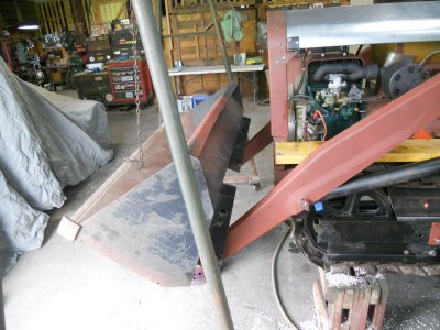
The cross tube is welded in place.
It is 3 inch diameter with 1/4 inch wall thickness.
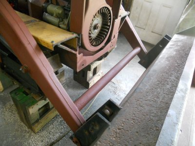
Here's how it looks so far.
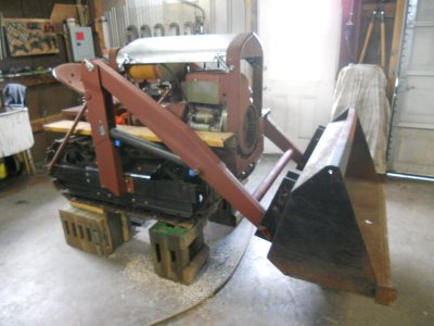
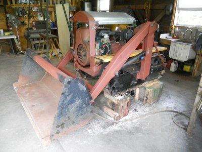
Here I'm checking to see how far back I want the bucket to tilt and marking it on the inside of the loader arms.
This is so I know where I can put in the support cross tube so it won't be in the way of tilting the bucket back.

The cross tube is welded in place.
It is 3 inch diameter with 1/4 inch wall thickness.

Here's how it looks so far.


Using the hydraulic cylinder mounts that I cut off the ends of the upper lift arms.
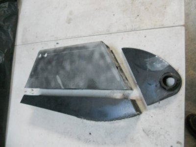
I took a piece of 2x3 inch rectangular boxed steel and cut it in half to form two square U-channel pieces.
The two mounting brackets fit on the inside of the channel piece and I've started welding them in place.
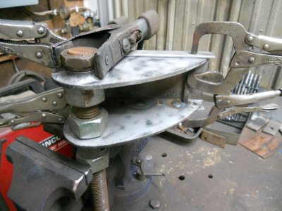
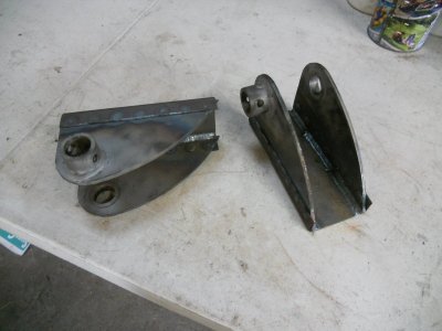
Here are the finished cylinder mounts.
I still have to grind the ends down where the square corners of the channel piece sticks up past the rounded edge of the brackets.
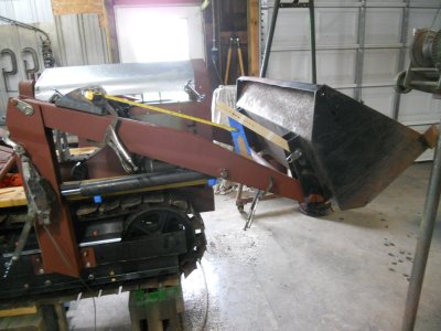
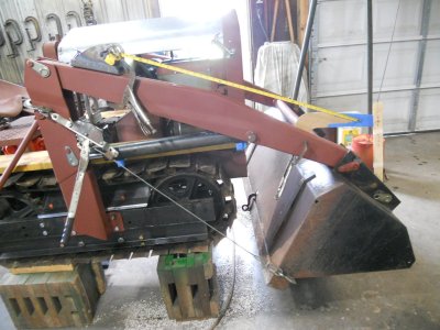
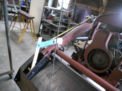
Figuring out what length and shape the brackets need to be so that the bucket can swing well over center.
The measuring tape is where the hydraulic cylinder will fasten in place.
This is with the cylinder fully retracted.
viewed from the inside.
View attachment 2634091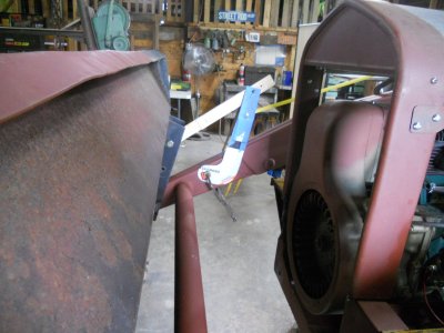
With the cylinder fully extended out.

I took a piece of 2x3 inch rectangular boxed steel and cut it in half to form two square U-channel pieces.
The two mounting brackets fit on the inside of the channel piece and I've started welding them in place.

Here are the finished cylinder mounts.
I still have to grind the ends down where the square corners of the channel piece sticks up past the rounded edge of the brackets.

Figuring out what length and shape the brackets need to be so that the bucket can swing well over center.
The measuring tape is where the hydraulic cylinder will fasten in place.
This is with the cylinder fully retracted.

viewed from the inside.
View attachment 2634091

With the cylinder fully extended out.


