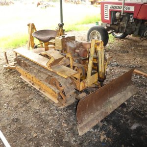
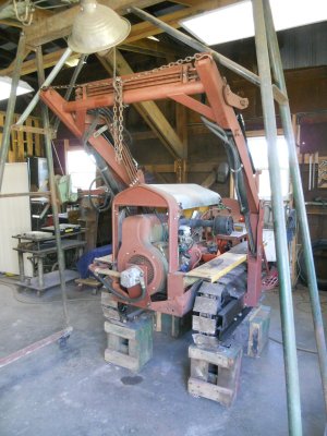
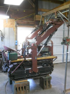
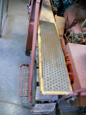
Agricat crawler model-F

The hub on the front of the engine has a double groove V-belt pulley machined onto it.

DSCN1833.JPG


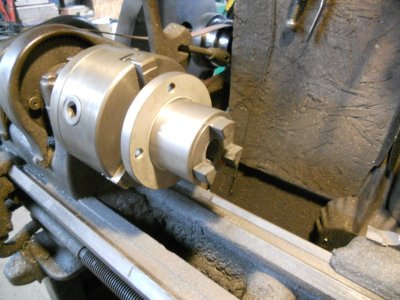
I took the hub off, shortened it and machined it out to accept a Lovejoy coupler.

DSCN2080.JPG


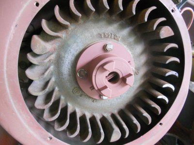
The modified hub is bolted back onto the engine.

DSCN2081.JPG


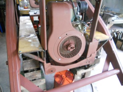
And the screen is fastened back on.

DSCN2082.JPG


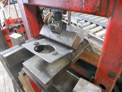
I'm using 1/4 inch thick steel plate to make the mount for the hydraulic pump.
Here I'm bending it to shape.

DSCN2083.JPG


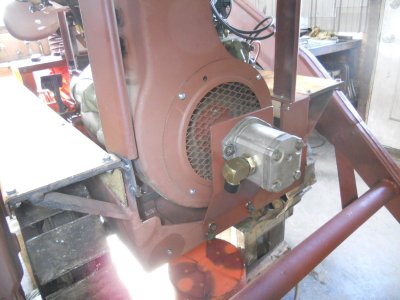
This bolts onto the front of the crawler frame to hold the pump in place.
This is the inlet side.

DSCN2085.JPG


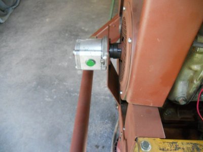
And this is the outlet side.

DSCN2086.JPG
 
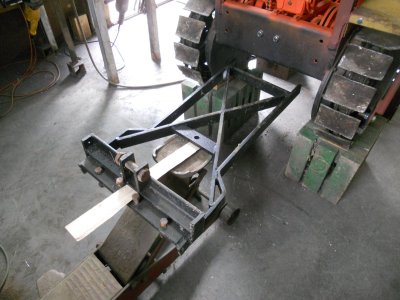
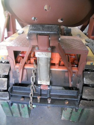
Lining up to fit the rear drawbar under the crawler.

DSCN2087.JPG


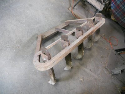
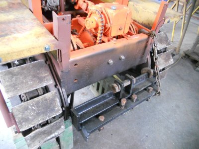
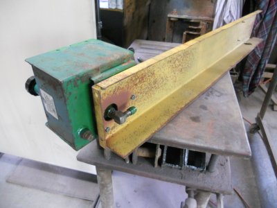
This is the scarfer that will bolt onto the rear drawbar.

DSCN2088.JPG


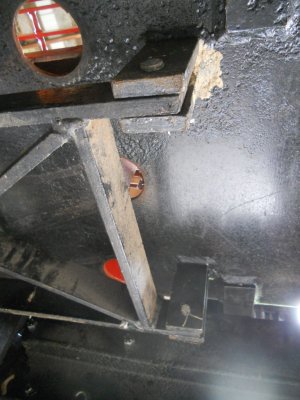
The front of the drawbar is fastened to two brackets under the center of the crawler.

DSCN2090.JPG


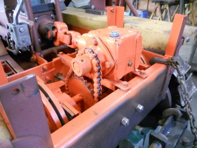
With the drawbar in place, I decided that I should change the drive sprocket before I mount that scarfer.

DSCN2089.JPG


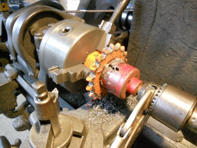
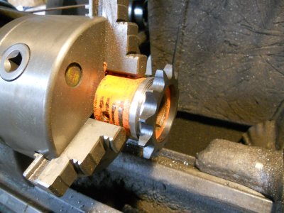
With the sprocket hub clamped up on the lathe, I'm using a hole saw to cut the sprocket off.

DSCN2091.JPG


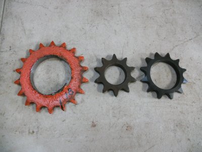
The original sprocket has 18 teeth.
I have a 10 tooth sprocket, which is close to half the size of the original but the bore in it is only 1-1/8 inch diameter.
The shaft on the drive is 1 inch diameter so that would only leave 1/16 wall thickness on the sprocket hub so obviously, that isn't going to work.
The smallest sprocket that I can safely go down to is a 12 tooth sprocket.
It has a 1-1/2 inch bore so the hub will have 1/4 inch wall thickness.

DSCN2093.JPG


The hub is turned down so the sprocket is a light press fit.

DSCN2094.JPG


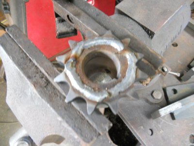
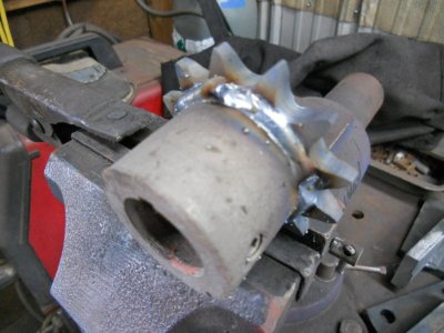
The sprocket is welded to the hub on both sides.

DSCN2097.JPG

DSCN2098.JPG


The welds are turned down just enough to clear the edge of the chain.
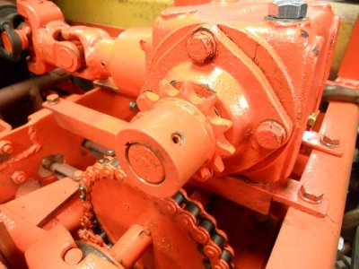
The sprocket is painted and mounted back on the drive shaft.

DSCN2099.JPG
 
Changing the drive sprocket worked out well.
To tension the chain, I only had to put a washer under each of the four corners of the mounting bracket for the right angle drive.

DSCN2101.JPG


I'm going to have to brake off this for awhile.
My son has a 1968 Firebird 400 and he wants to raise the center of the hood up two inches so I'm going to work on that for him.
I'm taking photos of the work on the hood and will post them in a another thread later.
 
Last edited:
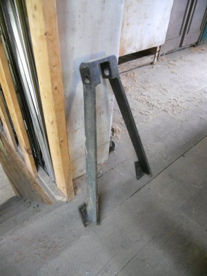
This is one of the original mounting brackets for the hydraulic cylinders on the Agricat crawler.

DSCN2158.JPG


These brackets were mounted on the front and the back and they stood straight up from the crawler frame.

01b.jpg


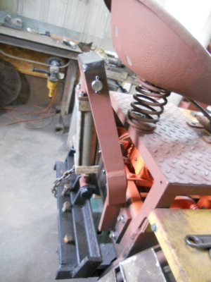
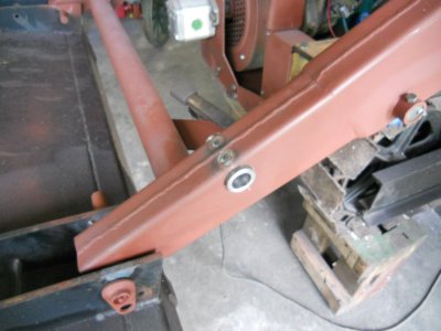
That worked fine on the original crawler because the seat was mounted further forward than what my seat is so I have had to cut the bracket and make it so it angles back to clear the seat.

DSCN2160.JPG


View from behind.

DSCN2161.JPG


Holes are drilled thru the loader arms and a piece of 1-1/2 inch diameter tube with 1/4 inch wall thickness is slid thru the holes and welded in place.

DSCN2171.JPG


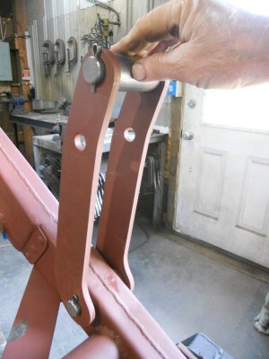
These are the two side linkage brackets.
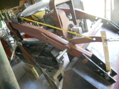
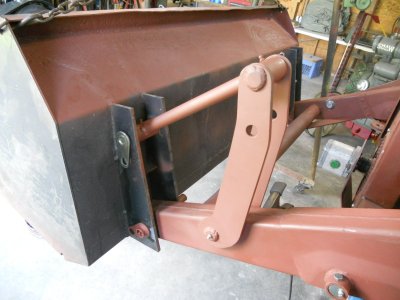
Here I'm making sure that the length of the front linkage arm is going to be correct so the bucket will rotate about 160 degrees.

DSCN2174.JPG


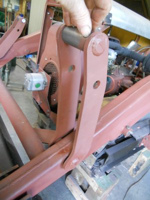
The pins for the two side brackets are assembled and they are each welded to the side bracket on the outside.
This keeps everything square and makes sure that the pins are rotating inside the pivot mounts.

DSCN2175.JPG


The inside side bracket is held in place by a cotter pin.

DSCN2176.JPG


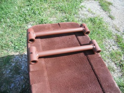
The two front linkage arms are each made up out of two pieces of the 1-1/2 inch tube and a piece of 1 inch solid bar.

DSCN2178.JPG


Here is how it looks when all assembled.
There are 9 grease fittings on each side of the loader arms.

DSCN2179.JPG
 
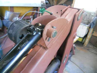
The upper hydraulic cylinders are mounted on the loader arms.

DSCN2180.JPG

DSCN2182.JPG

DSCN2183.JPG


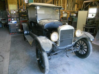
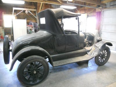
A friend of mine has gotten a 1926 Ford model-T that hasn't been run since 1993.

DSCN2187.JPG

DSCN2188.JPG


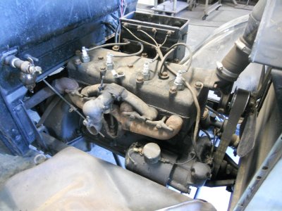
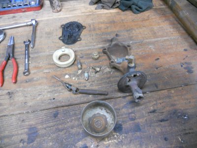
He asked me if I could get it running for him. I've taken the carburetor float bowl and vaporizer plate off.

DSCN2189.JPG


The parts are cleaned up and waiting on ordered parts to show up before I can put this back together.

DSCN2190.JPG


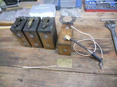
Three of the four coils worked ( kinda ) when we checked them. I'm going to clean them up and I have made up items to test and adjust them with.

The coil will be set upright with the bottom contact resting on the larger brass plate. This plate will be connected to the positive terminal on a battery.

The smaller brass piece will be clamped against the lower contact on the side of the coil. This is connected to a spark testing tool that has an adjustable rod to vary the opening of the gap that the spark will jump across.
This spark gauge will be connected to the negative terminal of the battery.

There is another wire soldered onto this spark gauge that will be used to touch against the upper contact on the side of the coil. The will energize the coil, making is " buzz " and producing a spark to jump across the gap in the spark gauge.

With this testing setup, I can adjust each coil to get a nice even spark.

DSCN2191.JPG
 
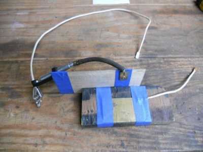
This the back side of a quick fixture that I made up to adjust and test the coils.
The positive clamp from the battery charger will be connected to the wire on the big brass plate on the bottom.
The ground clamp will be connected to the smaller brass plate on the side.
DSCN2192.JPG


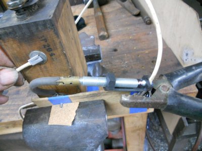
The coil is set into this fixture and it is clamped in a vice to hold the coil tight to the contact points and the battery charger clamps are hooked up.
When I touch the wire from the ground clamp to the upper contact on the coil, it produces a spark.
It's kind of hard to see here but there is a nice hot spark jumping between the open points on the spark tester.
DSCN2194.JPG


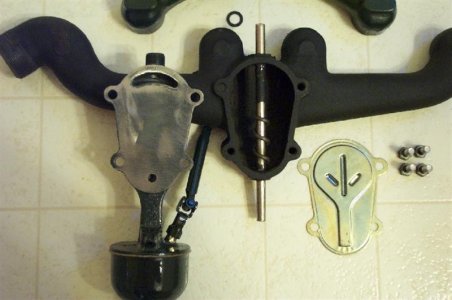
This is a view of a vaporizer carb taken apart. This shows the back side of the float bowl and the vapor manifold above it. The bolts on over the open space on the side of the exhaust manifold with a this tin cover plate in between them. The fuel flows up across that tim plate that is heated to 600 degrees by the exhausts on the other side of it. As soon as the liquid fuel touches that tin plate, it is instantly vaporized. This fuel vapor is then drawn up to the air valve on top of the manifold where it is mixed with the air to flow into the cylinders.
h44118.jpg


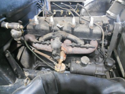
I have never worked on the vaporiser carburetors that were available on the newer 1926 and 1927 Ford model-T but from what I've read on the internet, it is very important not to have any vacuum leaks. So I used the red heat resistant RTV sealer on both sides of the thin vaporizer plate when bolting it back onto the manifold and also on the tubes going in and out on the float bowl and manifold.
DSCN2198.JPG


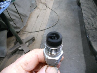
I got the engine running but it runs very rough. When I pulled the spark plugs they were all covered with a thick black soot so it is running way too rich.
DSCN2204.JPG


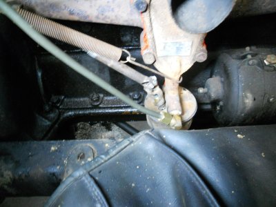
The instructions on the internet say to have the mixture screw on the top of the float bowl turned out 1-1/4 to 1-1/2 turns, which I did. After checking and cleaning the plugs. I turned this mixture screw all the way in to close it up completely and plugs are still soot covered the same as before.
DSCN2199.JPG


This is the firing order for the model-T. The commutator ( distributor cap ) is mounted right on the front of the camshaft. To time the commutator, you set the distance of 2-1/2 inch between the center of the pullrod on the commutator and the center of the bolt to the left of it the holds the retaining strap in place. This is set as specified.
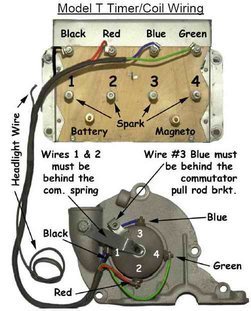
h277634.jpg


Checking the spark at the top of the spark plugs shows the all four coils are putting out a nice hot spark and obviously the spark plugs are fouling out from the over rich gas mixture.
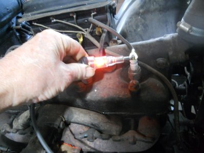
DSCN2202.JPG


So ... after showing the owner what I've got, we have decided to remove this intake and exhaust manifold and go back to this regular intake and exhaust manifolds and carburetor that Ford used on the model-T's from 1909 thru 1927.

We are doing this for two reasons. First, even if this carburetor had worked fine, that thin vaporizer plate only last about three or four years and has to be replaced. Second, the regular style carburetors have worked just fine on millions of model-T's for hundreds of years.

Obviously, Henry wasn't satisfied with the newer vaporizer carb system because he went back to the regular updraft carb system on the model-A's.
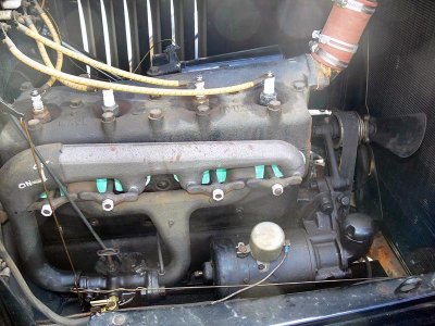
hotairpipe-vi.jpg
 
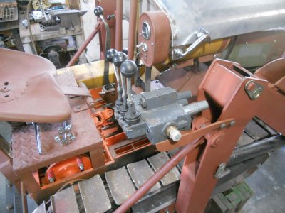
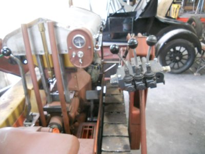
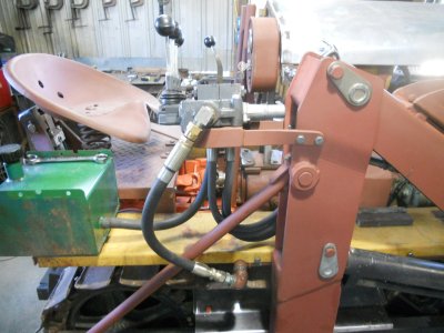
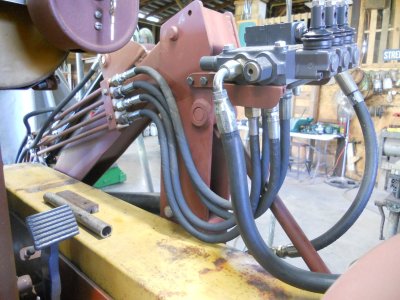
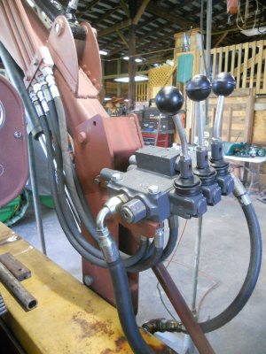
The hydraulic controls are mounted.

DSCN2206.JPG


I have them set at an angle. They are surprisingly more comfortable to reach at this slight angle.

DSCN2208.JPG


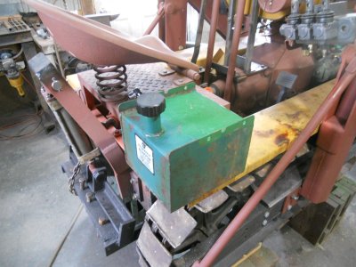
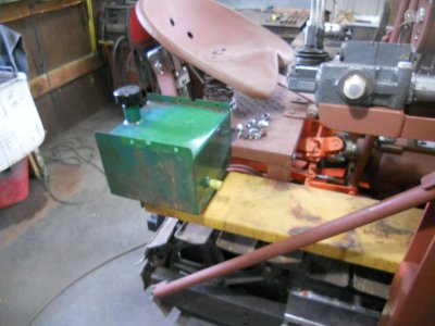
The tank sits on the back of the right fender.

DSCN2210.JPG


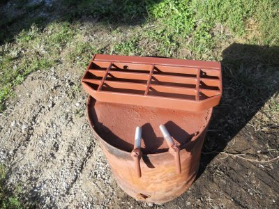
This is the return line fitting on the front side of the tank.

DSCN2211.JPG


The outlet fitting is on the underside of the fender.
This will have a steel line going all the way up to the front of the fender to connect with the inlet fitting on the pump.

DSCN2214.JPG
 
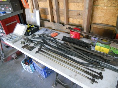
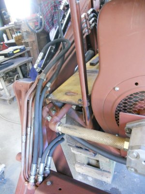
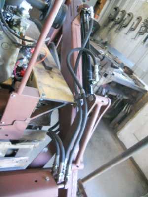
Getting hydraulic hoses and fittings organised.

DSCN2229.JPG


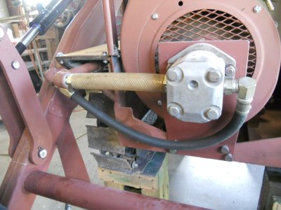
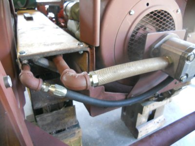
The inlet and outlet lines are run to the pump.
None of the lines are tight yet because they will all have to be removed when the crawler is ready for painting.

DSCN2232.JPG


The pressure line from the pump is also run under the fender.

DSCN2233.JPG


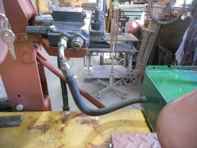
The pressure line comes out the side of the fender and runs up to the valve.

DSCN2236.JPG


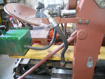
This is the return line from the valve down to the tank.

DSCN2237.JPG
 
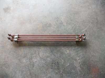
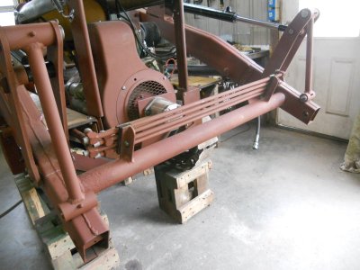
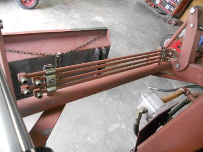
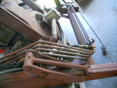
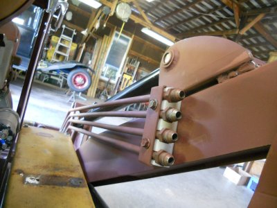
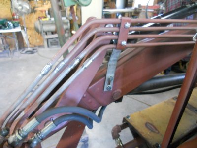
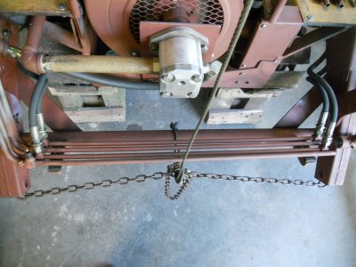
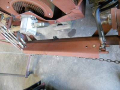
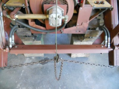
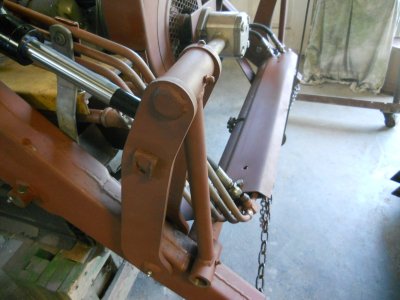
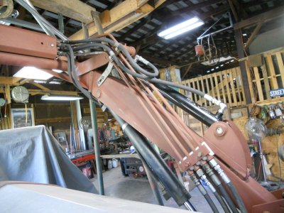
The hard hydraulic lines that ran across the front of the loader frame are mounted to two brackets.
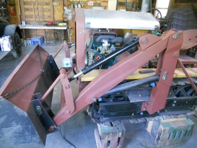
DSCN2242.JPG


This assembly is then welded to the cross tube on the loader frame.
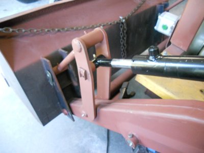
DSCN2244.JPG

DSCN2245.JPG


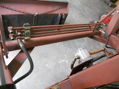
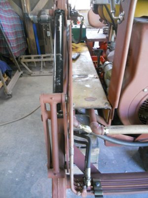
Two of the hydraulic hoses are hooked up to the hard line.

DSCN2247.JPG


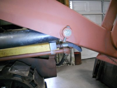
These two hoses go to the return port on each lift cylinder.

DSCN2248.JPG
 
Back
Top