You are using an out of date browser. It may not display this or other websites correctly.
You should upgrade or use an alternative browser.
You should upgrade or use an alternative browser.
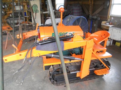
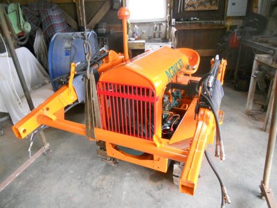
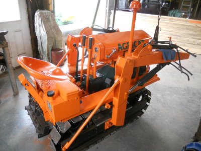
Agricat crawler model-F
- Thread starter jdcrawler
- Start date
Go to any air conditioning supply house and ask for a gallon Kleen Brite Coil Cleaner in the PINK bottle or the Zep brand. Mix it as described, USE GOOD RUBBER gloves and you will be amazed with the results. Wet the aluminum down first with water, work an area with the coil cleaner by spraying it on, let it FOAM UP and then wash it off with a water hose.Last minute engineering change.
I have decided to put an aluminum radiator in the hydraulic return line to cool the hydraulic fluid.
View attachment 92366
The rear mount is made up from a piece of 1/8 inch thick steel strap.
This strap fits under the gas tank mounting strap and the cooler is fastened to it with a rubber covered steel clamp.
View attachment 92367
The front mount is a piece of pickup bed strap from my 59 Chevy truck.
The two ends are fastened to the grille support rods with small steel clamps and the cooler is fastened to it with two of the rubber covered clamps.
View attachment 92368
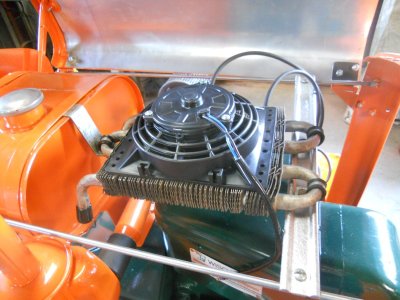
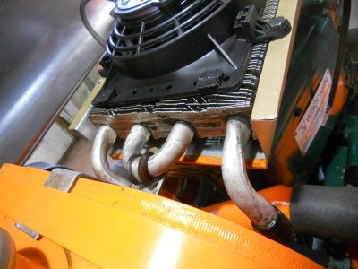
This shows the clearance for the spark plugs.
I have a 6 inch, 12 volt electric, radiator cooling fan ordered to fit on top of the cooler.
View attachment 92369
Let it really foam up like this example.
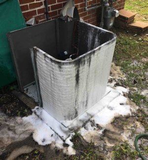
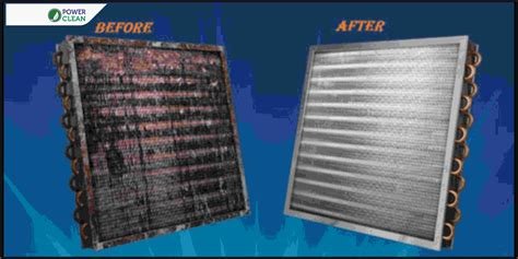
BUT, do NOT use EZ-Off oven cleaner.
The difference would be like this example,
This fan draws air up thru the cooler so I have made an air duct to fit under the cooler.
This duct is made out of aluminum and is also a heat shield to block the heat off the top of the engine.
The front of the duct extends out closer to the grille shell to draw in cooler air from in front of the engine.

The air duct also extends out a little ways past the back end of of the cooler.
There is about 1-1/4 inch air space under the cooler.
this is plenty of air space with the volume of air that the fan draws.
As you can see, it is open all the way thru so the air can be drawn from both the front and from the rear of the duct.
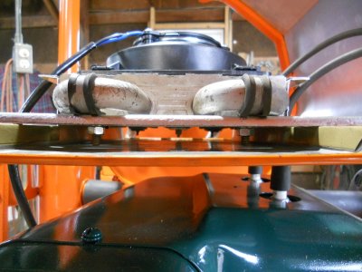
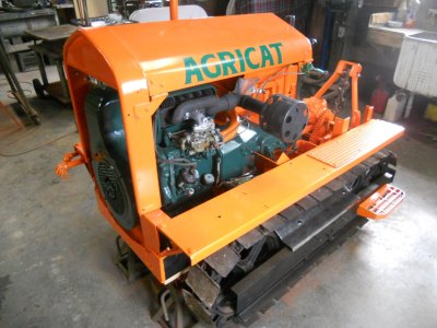
I do not know the exact year of this crawler but the Agricat crawlers were built in the 1950s and 1960's.
Because the hydraulic cooler is something that would most likely not have been on a little crawler back then, I have wanted to keep it so it doesn't show with the hood down.
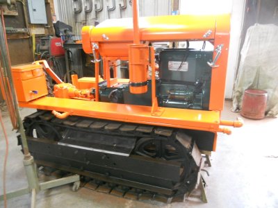
This duct is made out of aluminum and is also a heat shield to block the heat off the top of the engine.
The front of the duct extends out closer to the grille shell to draw in cooler air from in front of the engine.

The air duct also extends out a little ways past the back end of of the cooler.

There is about 1-1/4 inch air space under the cooler.
this is plenty of air space with the volume of air that the fan draws.
As you can see, it is open all the way thru so the air can be drawn from both the front and from the rear of the duct.

I do not know the exact year of this crawler but the Agricat crawlers were built in the 1950s and 1960's.
Because the hydraulic cooler is something that would most likely not have been on a little crawler back then, I have wanted to keep it so it doesn't show with the hood down.

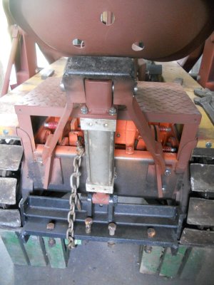
Would I assume the back end has a sleeve hitch? If so, how does it raise and lower?I was able to get some of the loader parts on the crawler today.
View attachment 93121
View attachment 93122
View attachment 93123
Got a little more work done today.
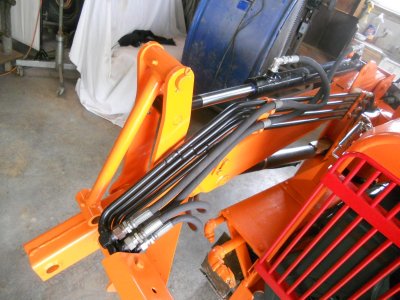
The bucket control arms are assembled on both sides and the upper hydraulic cylinders are connected to them.
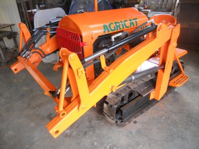
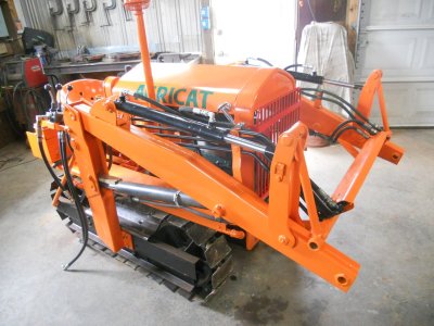
The hard hydraulic lines are mounted in place and the hoses for both the upper and lower cylinders are fastened to them on both sides.
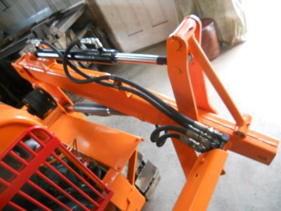
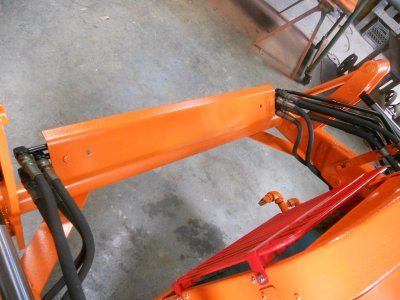
There is a steel panel mounted on top of the crossbar to protect the hard lines from getting damaged from anything falling off the back of the bucket.
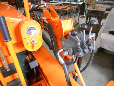
The hydraulic controls are mounted and the hoses are connected to the hard lines for the loader.
The bucket control arms are assembled on both sides and the upper hydraulic cylinders are connected to them.


The hard hydraulic lines are mounted in place and the hoses for both the upper and lower cylinders are fastened to them on both sides.


There is a steel panel mounted on top of the crossbar to protect the hard lines from getting damaged from anything falling off the back of the bucket.

The hydraulic controls are mounted and the hoses are connected to the hard lines for the loader.

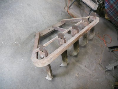
Looking really good JD, I like the ripper teeth alsoGot a little more work done today.
The bucket control arms are assembled on both sides and the upper hydraulic cylinders are connected to them.
View attachment 93146
View attachment 93151
The hard hydraulic lines are mounted in place and the hoses for both the upper and lower cylinders are fastened to them on both sides.
View attachment 93149
View attachment 93147
There is a steel panel mounted on top of the crossbar to protect the hard lines from getting damaged from anything falling off the back of the bucket.
View attachment 93148
The hydraulic controls are mounted and the hoses are connected to the hard lines for the loader.
View attachment 93152
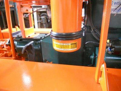
The hydraulic pump is mounted on the front and the hydraulic feed hose and pressure hose are hooked up.
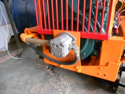
The hydraulic pressure hose is hooked up to the outside of the hydraulic valve.
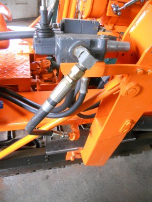
The two hydraulic hoses are run back for the rear cylinder.
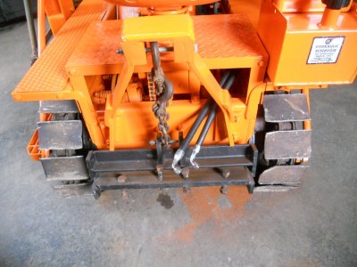
This is the return hose that had originally fastened onto the fitting on the bottom of the hydraulic tank.
This hose now needs to be replaced with a longer hose to go up to the cooler and then another hose needs to be made up to go from the cooler back to the fitting on the tank.
Obviously, there isn't any hydraulic fluid in the system yet.
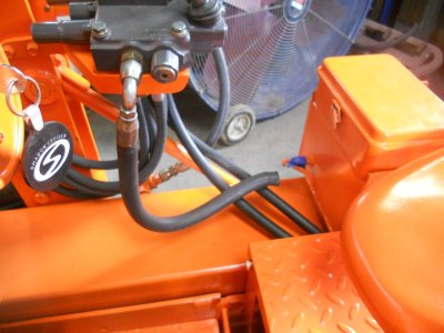
You'll note that the loader arm is not being held up by the overhead cable winch.
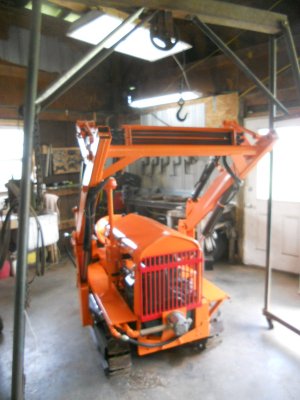
I have never trusted hydraulic lift systems or winch systems to never break and let whatever they're holding up to suddenly drop down ( as here with the loader arm up and me, underneath it, mounting the pump ).
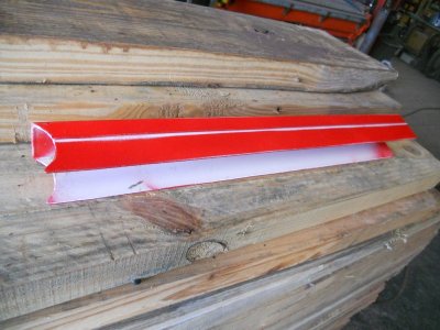
I have made up a safety stop out of a piece of aluminum U-channel.
This fits over the shaft on the hydraulic cylinder to keep the cylinder from closing and dropping the loader arm down.
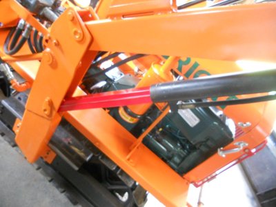
This is that safety stop.
There are rubber pads fastened onto the top of the gas tank and a steel pin sticking up with a piece of rubber hose over it.
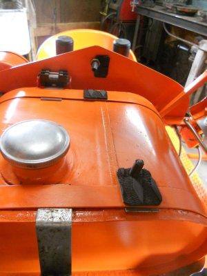
This is where the safety stop will be stored when not in use.
When showing my Lindeman crawler, I sometimes like to display it with the loader up and I have safety stops built into the loader arms on it.
I'll want to sometimes display this little crawler with the loader up so I want the safety stop to be readily available at any time.

The loader arm is lowered back down to make it easier to work on the hydraulic hoses going to the cooler.
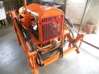

The hydraulic pressure hose is hooked up to the outside of the hydraulic valve.

The two hydraulic hoses are run back for the rear cylinder.

This is the return hose that had originally fastened onto the fitting on the bottom of the hydraulic tank.
This hose now needs to be replaced with a longer hose to go up to the cooler and then another hose needs to be made up to go from the cooler back to the fitting on the tank.
Obviously, there isn't any hydraulic fluid in the system yet.

You'll note that the loader arm is not being held up by the overhead cable winch.

I have never trusted hydraulic lift systems or winch systems to never break and let whatever they're holding up to suddenly drop down ( as here with the loader arm up and me, underneath it, mounting the pump ).
I have made up a safety stop out of a piece of aluminum U-channel.
This fits over the shaft on the hydraulic cylinder to keep the cylinder from closing and dropping the loader arm down.

This is that safety stop.

There are rubber pads fastened onto the top of the gas tank and a steel pin sticking up with a piece of rubber hose over it.

This is where the safety stop will be stored when not in use.
When showing my Lindeman crawler, I sometimes like to display it with the loader up and I have safety stops built into the loader arms on it.
I'll want to sometimes display this little crawler with the loader up so I want the safety stop to be readily available at any time.

The loader arm is lowered back down to make it easier to work on the hydraulic hoses going to the cooler.

That is an excellent safety stop JD, I fabricated and use one like that when I work on my loader tractor, as you posted rope chains cables straps and pipes and hoses can all brake suddenly without warningThe hydraulic pump is mounted on the front and the hydraulic feed hose and pressure hose are hooked up.
View attachment 93231
The hydraulic pressure hose is hooked up to the outside of the hydraulic valve.
View attachment 93228
The two hydraulic hoses are run back for the rear cylinder.
View attachment 93229
This is the return hose that had originally fastened onto the fitting on the bottom of the hydraulic tank.
This hose now needs to be replaced with a longer hose to go up to the cooler and then another hose needs to be made up to go from the cooler back to the fitting on the tank.
Obviously, there isn't any hydraulic fluid in the system yet.
View attachment 93230
You'll note that the loader arm is not being held up by the overhead cable winch.
View attachment 93232
I have never trusted hydraulic lift systems or winch systems to never break and let whatever they're holding up to suddenly drop down ( as here with the loader arm up and me, underneath it, mounting the pump ).
I have made up a safety stop out of a piece of aluminum U-channel.
This fits over the shaft on the hydraulic cylinder to keep the cylinder from closing and dropping the loader arm down.
View attachment 93233
This is that safety stop.
View attachment 93234
There are rubber pads fastened onto the top of the gas tank and a steel pin sticking up with a piece of rubber hose over it.
View attachment 93235
This is where the safety stop will be stored when not in use.
When showing my Lindeman crawler, I sometimes like to display it with the loader up and I have safety stops built into the loader arms on it.
I'll want to sometimes display this little crawler with the loader up so I want the safety stop to be readily available at any time.
View attachment 93236
The loader arm is lowered back down to make it easier to work on the hydraulic hoses going to the
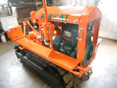
The hydraulic lines are all hooked up and the air is bled out of the system.
The loader arm is being held up by it's own hydraulic pressure.
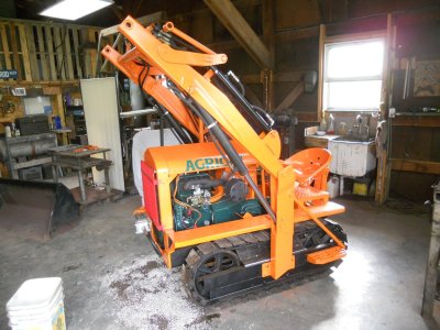
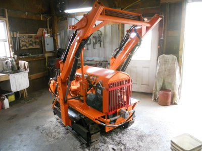
The rear hitch is also being held up by it's cylinder.
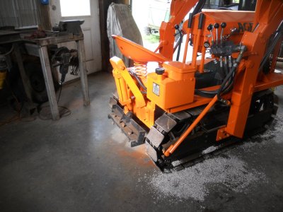
And of course, this is with the arm lowered.
I quickly realised that this pump has way too much capacity for this hydraulic system.
Just cranking the engine over on the starter alone will raise and lower the arm at a good rate of movement.
It moves way to fast with the engine running so I need to put a lower capacity pump on it.
This pump has a 1-1/16 SAE O-ring outlet and that size is rated at about 18 GPM.
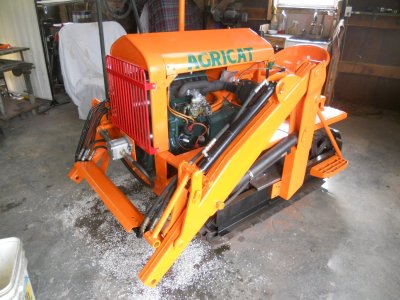
The loader arm is being held up by it's own hydraulic pressure.


The rear hitch is also being held up by it's cylinder.

And of course, this is with the arm lowered.
I quickly realised that this pump has way too much capacity for this hydraulic system.
Just cranking the engine over on the starter alone will raise and lower the arm at a good rate of movement.
It moves way to fast with the engine running so I need to put a lower capacity pump on it.
This pump has a 1-1/16 SAE O-ring outlet and that size is rated at about 18 GPM.

Last edited:

