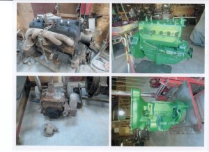
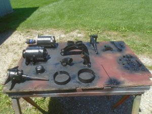
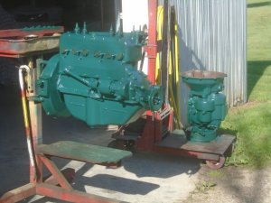
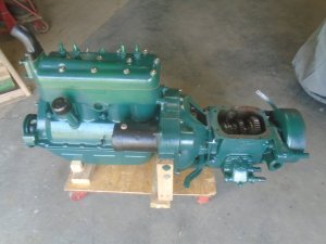
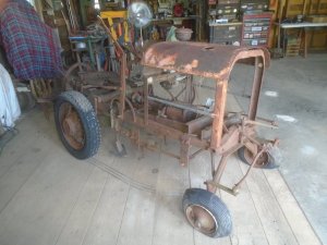
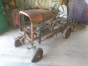
Ford model-T tractor converson

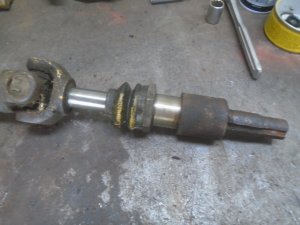
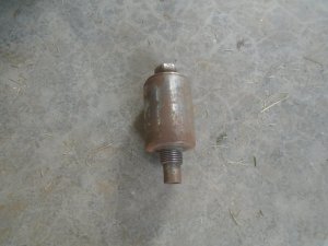
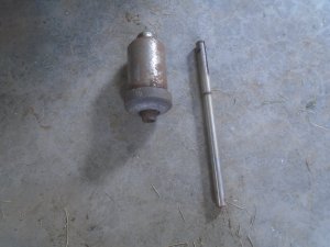
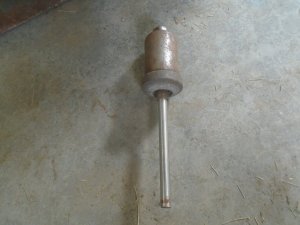
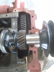
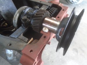
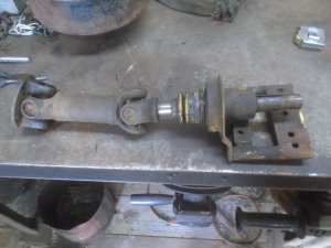
I have this small driveshaft off something ? It has a sliding yoke on the right end that has both a 1 inch and a 3/4 inch diameter shaft with a keyway in them.
DSC06193.JPG

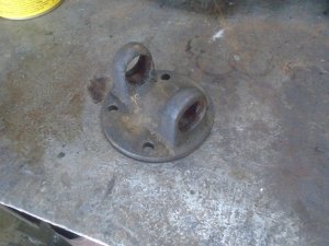
The U-joint mounting flange is removed from the left end of the driveshaft.
DSC06194.JPG


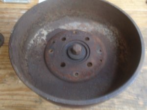
I want to fasten this mounting flange to the center of the brake drum on the back of the transmission but I'll need a spacer to clear the bolt in the center that holds the drum onto the transmission.
I have already pressed the studs out of the drum.
DSC06195.JPG


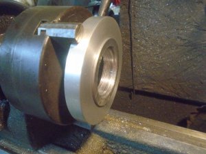
This piece of aluminum is just big enough diameter to clear the studs in the drum.
I have turned it down to leave a lip that fits into the counter-bore in the center of the drum.
DSC06196.JPG


Then I turn it around and machine a counter-bore that the U-joint flange fits into.
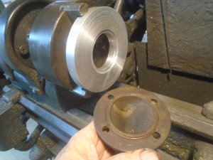
DSC06197.JPG


The holes are drilled out and counter-board in the spacer so it fits over the studs and can be bolted down.
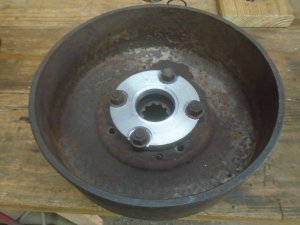
DSC06199.JPG


I've had to notch out four places around the U-joint flange to clear the nuts on the studs. The first hole is drilled and tapped for the studs to fasten the U-joint flange in place.
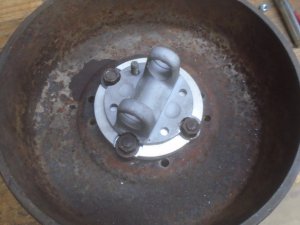
DSC06200.JPG


The finished U-joint flange is mounted to the drum.
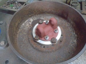
DSC06201.JPG


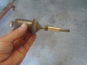
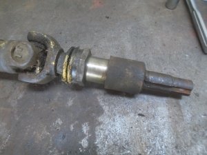
I'm going to take just the end piece with the sliding joint and it will be mounted onto the flange on the drum.
This gives me one end of a driveshaft with either a 1 inch or 3/4 inch shaft that should be easy enough to adapt to the model-T rear axle.
This is the length of the shaft when closed.
DSC06202.JPG


And the length when fully open.

DSC06204.JPG
 
Last edited:
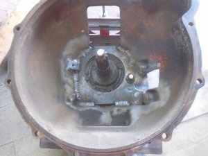
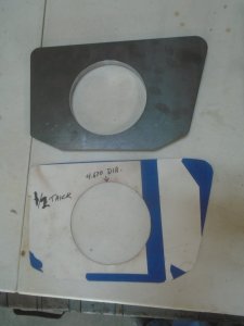
I made up a cardboard pattern of the front of the transmission for the adapter plate and gave it to my son.
He is an engineer for a company that manufactures all sorts of suspension and running gear parts for the ATV market.
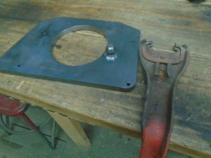
He had the adapter plate cut out of 1/2 inch steel on their laser cutting machine.

DSC06207.JPG


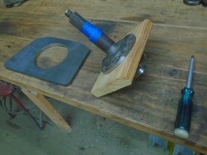
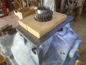
The transmission input shaft is fastened to a piece of wood so it is the same length as it would be when bolted to the front of the transmission.

DSC06210.JPG


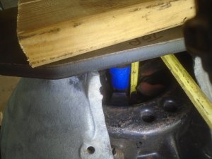
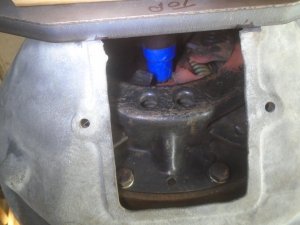
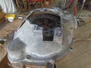
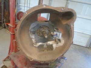
The adapter plate is set on top of the cutoff bellhousing and the input shaft is set in place so I can gauge how much still needs to be machined off the bellhousing. The bottom edge of the blue tape is the depth of the input shaft when it is bottomed out on the crankshaft.
I also mark the bellhousing where the bottom edge of the adapter plate will be.

DSC06211.JPG


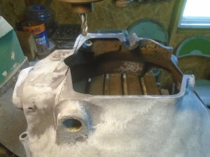
The bellhousing is set back up on the mill and it is lined up the the line for the bottom edge of the adapter plate.

DSC06212.JPG


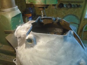
The bellhousing is cut along this edge mark and to the depth of the finished depth.

DSC06213.JPG


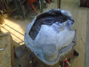
The rest of the surface of the bellhousing is then machined off and I put the bellhousing back on the engine.

DSC06214.JPG


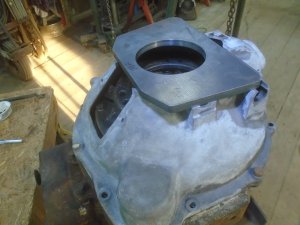
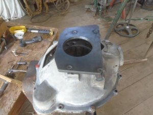
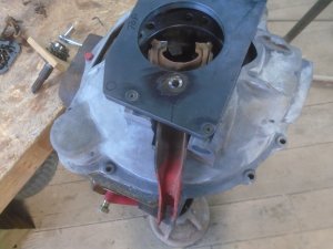
The adapter plate is set in place.

DSC06215.JPG


And the input shaft is set in place.
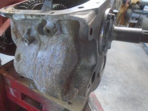
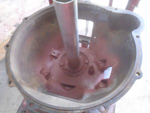
You can see here how the bottom edge of the adapter plate rest up against the step in the bellhousing. This way, the weight of the transmission when it is bolted to the adapter plate will be supported by the cast iron bellhousing itself and not just by the welds.

DSC06216.JPG


The input shaft now has about .100 clearance from bottoming out on the crankshaft.

DSC06217.JPG
 
Over the years I have made several transmission adapters but they have all been for automatic transmissions.
Those are simple. all you have to do is mate the starter flex plate and torque converter to the end of the crankshaft and make a plate to bolt to the back of the engine so the transmission can bolt to it.

This adapter is much more difficult.
I have the bellhousing cut down so the transmission input shaft sits at the right depth now. everything is lined up on center and I have secured the steel adapter plate to the bellhousing with four, counter sunk allen screws.
These not only hold the adapter plate in place while I finish doing other machine work, it will keep it secured later when I weld the adapter plate to the bellhousing.

DSC06219.JPG


I have to use a Chevy clutch disk to fit the transmission and I have to use the Ford pressure plate to fit the flywheel.
At this point, I'm ready to figure out where the Chevy clutch throw-out arm is going to go.

DSC06220.JPG


The hole for the throw-out arm is cut into the side of the bellhousing.

DSC06221.JPG


The rounded pin that the throw-out arm pivots on is mounted onto the back of the adapter plate and welded in place.

DSC06222.JPG


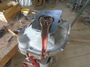
Checking the fit.
DSC06223.JPG


The throw-out bearing poses a big problem.
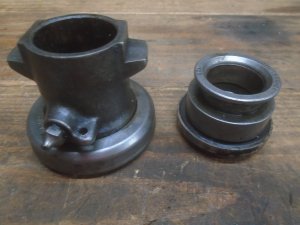
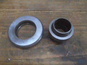
This is a model-A throw-out bearing and a Chevy throw-out bearing.
The model-A bearing is a lot bigger diameter than the Chevy and the slide housing is a lot longer with a lot bigger bore and uses a completely different throw-out arm than the Chevy.

DSC06224.JPG


So I need to mate the larger model-A throw-out bearing onto the smaller Chevy slide housing.

DSC06225.JPG


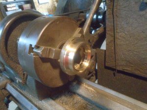
To do that, I've machined out a brass adapter collar.

DSC06228.JPG


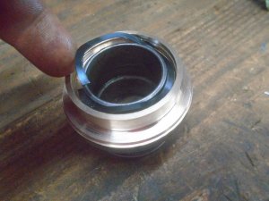
This fits onto the Chevy slide housing and is held in place with the spring ring just like the original bearing was.

DSC06229.JPG


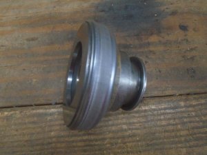
Then the model-A bearing is pressed onto it like it is on the model-A slide housing.
Now I have a model-A throw-out bearing that is the correct length to fit onto the Chevy transmission.

DSC06230.JPG
 
At this point, the input shaft is assembled back onto the front of the transmission.

DSC06256.JPG


Now the adapter plate can be centered on the transmission so the location of the mounting holes can be marked.
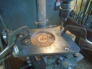
The plate is put up on the drill press and the mounting holes are drilled and taped.

DSC06257.JPG


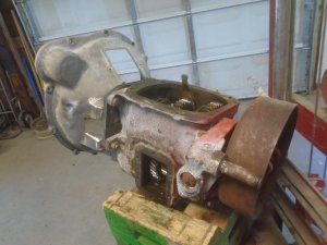
The adapter plate is bolted back onto the bellhousing with the countersunk allen screws and then the transmission is bolted to it.

DSC06258.JPG

DSC06259.JPG

DSC06260.JPG


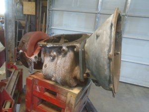
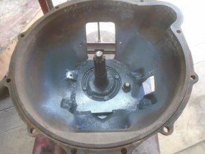
The adapter plate and the bellhousing are welded together on the inside. This way, none of the welds are showing on the outside.

DSC06261.JPG


The welds are cleaned and primed.

DSC06262.JPG


And finely painted to help keep them from rusting.

DSC06263.JPG
 
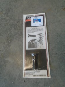
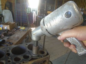
Snyder's Antique Auto Parts sells this slick little tool for removing the valve guides from the block.

DSC06264.JPG


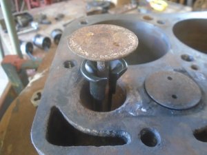
With the valve spring removed from underneath, the tool is set down under the valve.

DSC06265.JPG


The instructions on the package show that you can tap the valve guide out with the heal of your fist.
Well .. that might have worked 60 years ago but I had to use a hammer to get them out. Still, it didn't take much force to get the valve guides to move.

DSC06266.JPG


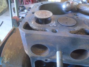
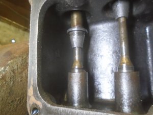
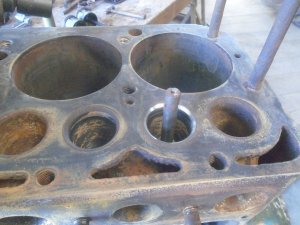
The valve guide drops out from below.

DSC06267.JPG


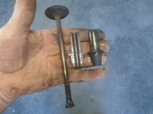
The guides themselves are made in two pieces and they split apart once they are out of the block.
The valve is then lifted out from the top.

DSC06269.JPG


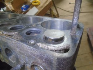
I used my die grinder to get down inside the pockets and clean them up.

DSC06270.JPG


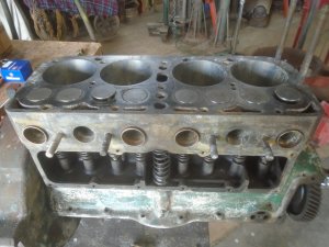
Then I took the block outside and cleaned it off good.
I'm ready now to grind the valve seats in the block.

DSC06271.JPG

DSC06272.JPG
 
Luckily, my son has this old hand operated valve grinding set for grinding the valve seats in the block.

DSC06273.JPG


It consist of arbors that have bearings inside with a hex head on one end and a thread on the other end.

DSC06274.JPG


The grinding stone is screwed onto it and the arbor then fits onto these guide pins.

DSC06275.JPG

DSC06276.JPG


The guide pins come in different sizes to fit into different size valve guide bushings.
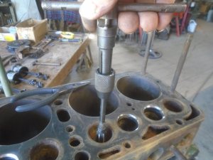
With this engine not having the valve guide bushings in it, I had to make up a brass sleeve to fit down into the block with the guide pin resting in it.

DSC06278.JPG


The arbor is spun with the hand held electric motor.

DSC06279.JPG


Here is the first finished valve seat.

DSC06280.JPG


My brass sleeve fits nicely into the four intake valve guide holes. These were the ones where the valve guides came out the easiest. I had to use more force to get the valve guides out of the exhaust ports and my brass sleeve doesn't fit into them.
I'm using a hand reamer to clean these holes out just enough so my brass sleeve fits into them. This will also make the fit more uniform when I go to install the new valve guides.

DSC06281.JPG


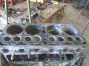
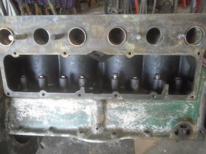
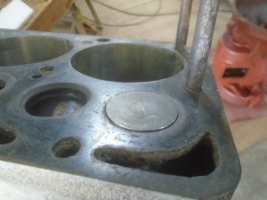
The valve seats are all ground smooth. Each valve will be hand lapped into the seat to finish the valve grind job.
I have sprayed the block with Eastwood's Oxisolv to remove the light surface rust that is already starting to form after I had cleaned the block.
It leaves that white coating on it to prevent rusting.

DSC06282.JPG
 
I'm replacing the solid lifters with a set of adjustable lifters.
I have also put steel sleeves into the exhaust ports. The sleeves they sell are split so they can adjust to any difference in the diameter of the holes.
I make my own sleeves that are solid all the way around and machined to fit snugly into each hole.

DSC06295.JPG


The new valves are extra long and even with the lifters adjusted all the way down, the end of the valves still need to be ground down a little.
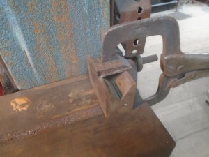
I clamped a V-block onto the belt sander at 90 degrees to the belt.

DSC06296.JPG


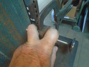
Holding the valve in the V-block with two fingers, I can then push the end of the valve into the sanding belt, rotating it as I do this.

DSC06297.JPG


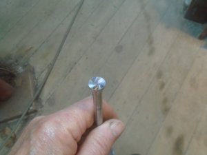
This leaves a nice flat " swirly " finish on the end of the valve.

DSC06298.JPG


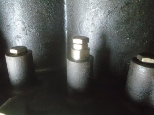
These lifters have a center lock nut between the head and the body of the lifter.

DSC06301.JPG


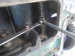
The valve is installed in the block with the spring and the valve keeper in place.
Then three wrenches are needed to hold the lifter body, adjust the head of the lifter and tighten the lock nut.

DSC06302.JPG


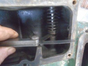
I use a go - nogo feeler gauge to set the clearance.

DSC06303.JPG


This is the valve closed.

DSC06304.JPG


And this is the valve open.

DSC06305.JPG


All of the valves are installed and the clearance set on each one.

DSC06307.JPG
 
I'm sure all of you have seen pistons installed in and engine at one time or another so I'm not going to bother with taking photos of that.
So, with the pistons all in and everything tightened down, it's time to start putting the engine back together starting with the timing gear cover.

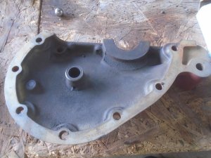
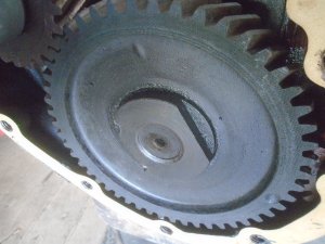
I haven't paid much attention to that part and as soon as I picked it up, I knew that I had another problem. That boss on the inside with the hole in it is suppose to hold the spring loaded plunger that rides against the end of the camshaft to keep it from sliding forward.

DSC06349.JPG


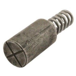
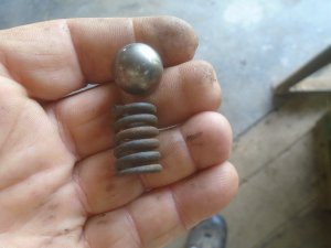
This is what that plunger looks like and I realize now that there wasn't one in there when I pulled the cover off.
A new timing gear has been put on this engine at one time and they forgot to put the plunger back in when they put the cover back on.
I can order one at $3.99 for the plunger and $12.76 for shipping and I wouldn't get it until Tuesday - at the earliest.
Naturally, this style of plunger is very old technology and the instructions for it says to be sure to grease it really good or it will make a nasty noise when you first start the engine.

DSC06350.jpg

Now days, there would be a hardened ball that would ride against the end of the cam with the spring putting pressure on it.
So I decided to up-date this old engine and I came up with a 5/8 diameter ball bearing and a spring just the right size.

DSC06351.JPG


There is already a chamfered hole in the center of the camshaft for the ball to ride on.
You can see here how good a condition the fiber cam gear is and you can tell that it has been changed because there are marks on the left side of the nut where they used a hammer and chisel to tighten the nut.

DSC06351a.JPG


With the spring and ball set into the cover, I held it up to the engine and you can see that there is about a 3/16 wide gap for compressing the spring.
That should be just the right amount of pressure on the camshaft.

DSC06352.JPG


The rope seal is fit into the cover and it is bolted on.
This leaves quite a bit of the rope seal sticking up that needs to be trimmed off.

DSC06353.JPG


The ends of the rope seal need to be trimmed off so you leave a little of it sticking out, both on this cover and on the oil pan, so the ends will be compressed together when the pan is bolted on.
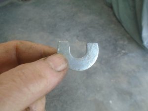
I use a washer that is about .100 thick and I've trimmed it to form a U-shape.

DSC06354.JPG


This is placed around the rope seal and then the ends can be trimmed off evenly with a razor blade.

DSC06355.JPG


This leaves a nice even amount of the rope seal sticking out.
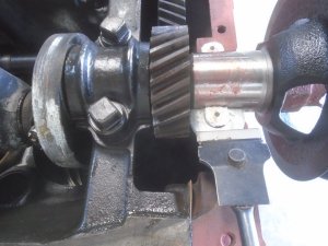
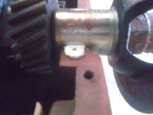
A light coating of grease is spread on the pulley shaft so there isn't a dry surface rubbing against the rope seal.

DSC06357.JPG


The rope seal on the oil pan is trimmed the same way and the pan is bolted onto the block.

DSC06358.JPG
 
Back
Top