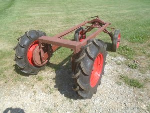
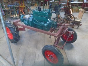
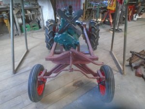
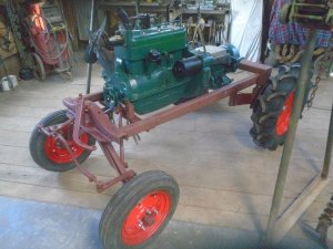
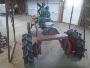
Ford model-T tractor converson

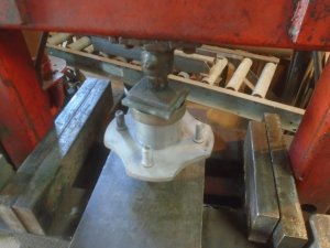
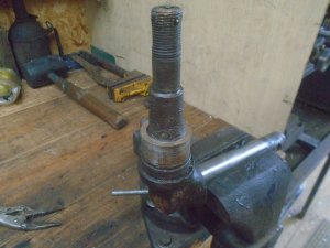
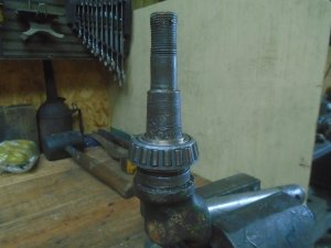
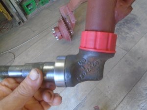
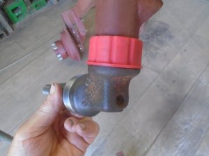
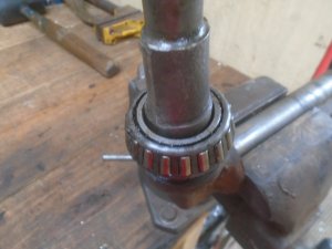
Checking the fit of the Mustang rear bearing on the tractor axle. The bearing is a little larger so just making up a sleeve will take care of fitting it onto the axle.
DSC06476.JPG


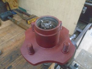
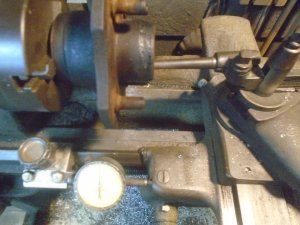
The Mustang hubs are put on the lathe to bore the hole for the tractor bearing race larger.
DSC06479.JPG


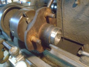
It is machined out to a light press fit on the bearing race.
DSC06480.JPG


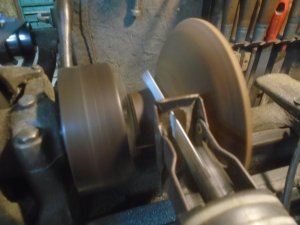
Naturally, the Mustang press in dust cap is no longer going to fit so I decided that I would like to use the screw on caps off the old tractor hubs.
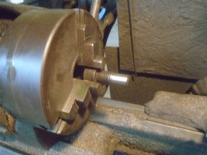
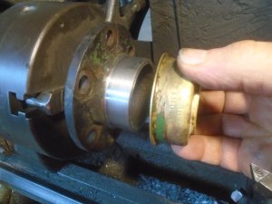
I chuck them up on the lathe and cut them off while the hubs are turning.
DSC06482.JPG


Then I face off the end and bore it out just enough so the bearing race will easily slide past it.
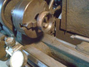
DSC06483.JPG


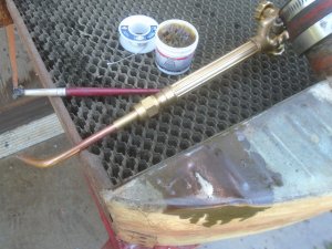
The end is brazed onto the end of the Mustang hub.
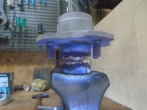
DSC06485.JPG


Then the outside is turned down a little.
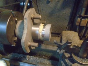
DSC06487.JPG


I cut two pieces of aluminized exhaust pipe to fit over the hubs.
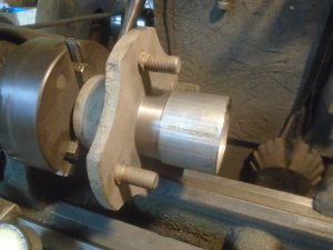
DSC06488.JPG


These are press fit onto the hubs.

DSC06489.JPG


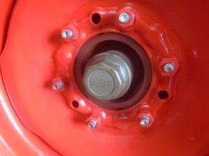
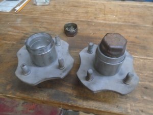
Here are the finished hubs with the dust cap screwed into one of them.
DSC06490.JPG
 
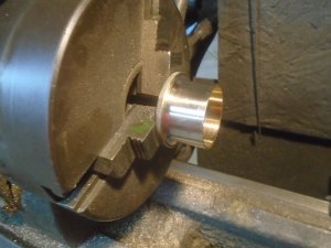
The center of a piece of brass is bored out so it fits over the axle spindle.

DSC06491.JPG


The outside of that brass piece is then turned down to form the adapter sleeve for the rear bearing race to fit onto.

DSC06492.JPG


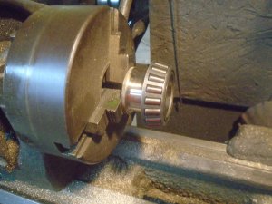
The sleeve is a light press fit into the bearing race.

DSC06493.JPG


Now the rear bearing fits onto the axle spindle.
DSC06494.JPG


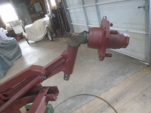
The Mustang hub can now be installed.
I discovered that the end of the spindle has cotter-pin holes drilled thru it so I found a couple of castle nuts that fit and I'm going to use cotter-pins to lock the spindle nuts in place.

DSC06495.JPG


The dust cap is screwed on and the spindle assembly is set into the end of the axle.

DSC06497.JPG


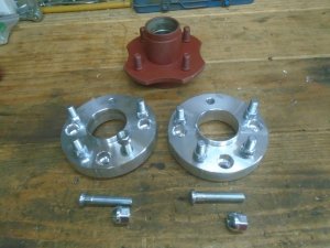
The 1965 Mustang hubs have 4-lug bolts and I have already picked up a pair of adapters so I can use regular 12 inch, 5-lug tractor wheels on these hubs.

DSC06498.JPG
 
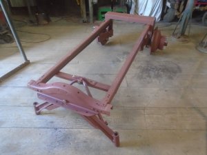
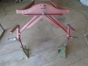
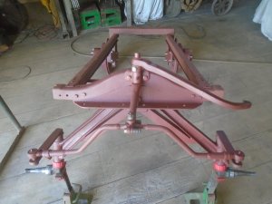
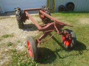
The frame is off the stands and turned right side up.

DSC06499.JPG


The front axle spindles are just metal to metal contact to support the weight of the tractor as they rotate in the ends of the axle housing.
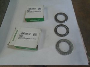
I got a pair of thrust bearings that I'm going to use on the front spindles.

DSC06500.JPG


I need something to fit over the outside of the thrust bearings to help keep the dirt out of them.
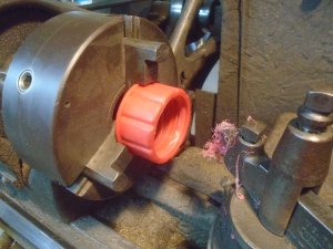
For that, I'm going to use the screw tops off the spouts from gas cans that I have changed the spouts on to convert then from non-vented to vented cans.
Here I'm boring the top out to fit over the end of the axle housing.

DSC06501.JPG


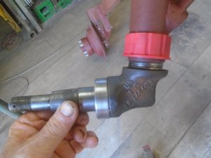
These are a tight fit onto the axle housing and here you can see how the thrust bearing is exposed by itself.

DSC06503.JPG


The gas cap dust shield is pushed down over the thrust bearing to protect it from the dirt.

DSC06504.JPG


As you can see here, the dust shield grips the axle housing and does not rotate with the axle spindle.

DSC06505.JPG


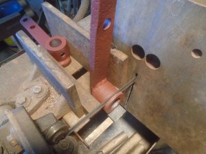
The thrust bearing makes the axle spindle set a little lower from the axle housing so I have to cut that much off the underside of the upper steering arms.

DSC06506.JPG


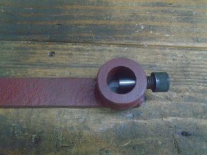
These steering arms have a 1/2-13 threaded hole in the back side of them. A regular 1/2 inch bolt screwed into the hole and tightened down on a dimple in the side of the shaft of the axle spindle to lock the steering arm in place.
I could see where these steering arms had already wobbled back and forth and wore the dimple out to the sides.

I have drilled a .390 diameter hole partway into the shaft and I'm turning down a grade-8 allen bolt to form a pin to fit into the hole in the shaft.

DSC06507.JPG


You can see here how the allen bolt will thread into the steering arm and the end of the bolt will tighten down on the end of the hole in the shaft to lock the arm in place.
This mount is not going to wobble loose or snap the bolt off.

DSC06509.JPG


The two steering arms are fastened onto the axle spindles.

DSC06510.JPG
 
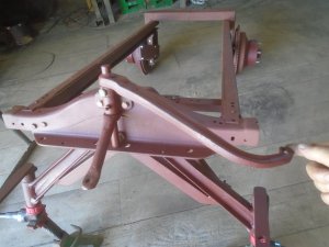
The steering arm is bolted to the frame.

DSC06511.JPG


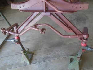
And the two tie-rod arms are fastened to the spindle arms.

DSC06512.JPG


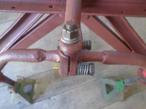
The ball is bolted onto the end of the steering arm and the two tie-rod arms are fastened to it to form the socket around the ball.

DSC06513.JPG


Originally, these two halves of the socket were bolted tight together with a washers held between them. This made it so that the ball had some slop inside the socket.
I bolted the two halves together without the washers in between them so the ball fit snugly in the socket. This worked out alright until I tried to make a full turn to the left or right. Then the ball and socket started to bind up a little.

To correct this, I used longer bolts with springs on them to hold the two halves of the socket together.
Now the ball and socket fit together snugly and there is enough flex so they don't bind up on full turns.

DSC06515.JPG
 
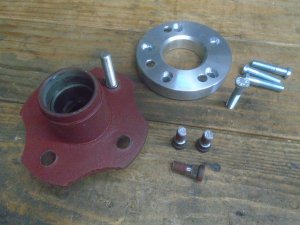
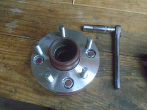
Working on fitting the wheel adapters onto the hubs. The lug studs in the hubs had to be shortened a little so they stay below the outside surface of the adapters.
One lug stud goes all the way thru the hub flange and the adapter.

DSC06516.JPG


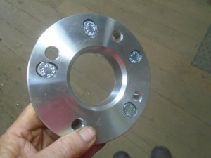
The back side of the adapters has slots milled into it that the head of the special lug studs fit into.

DSC06516a.JPG


The adapter is bolted onto the hub to convert it from 4-lug to 5-lug.

DSC06517.JPG


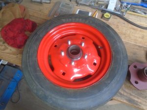
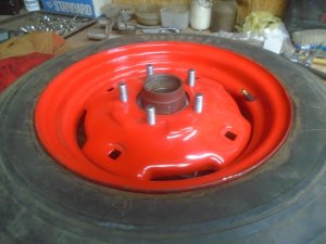
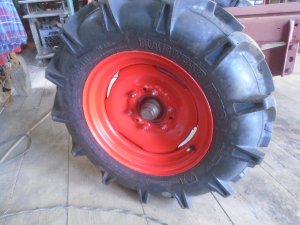
The 12-inch front wheel of a Farmall cub fits onto the hub now.

DSC06518.JPG

DSC06519.JPG


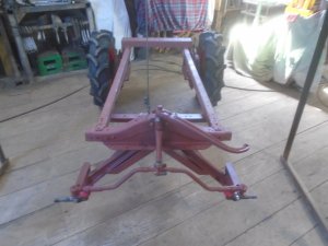
The front axle is ready to have the wheels installed. All I'm waiting on is for the grease seals for the hubs to show up.

DSC06520.JPG


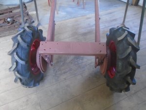
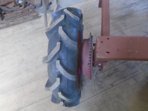
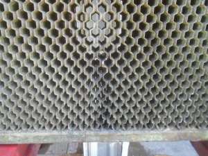
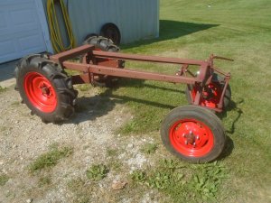
The 8.00x16 inch rear tires are mounted on the tractor.

DSC06521.JPG


Outside to outside width of the tires is a little over 4-foot wide.

DSC06523.JPG


There is about 3-inches clearance between the side of the tire and the chain sprocket on the rear drums.

DSC06524.JPG
 
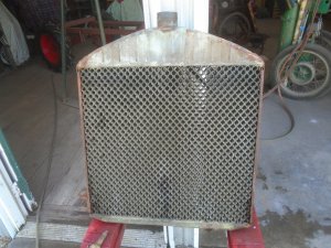
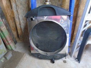
Interesting project today. Checking out the old model-T radiator that I have and It isn't as bad as I thought it would be.

DSC06525.JPG


Small leak in the center of the front about 6 inches up in the core ( you can see a shiny spot of solder ).

DSC06526.JPG


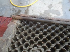
Two leaks on the back lower left side.

DSC06527.JPG


And a small crack in the top tank.

DSC06528.JPG


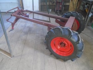
I was able to solder the crack in the tank up completely and I was able to solder up the spots in the core to where there is just a some small drips. I'll run some Bars-leak, powder pellets in the coolant and that will seal up the small drips.

This radiator was built in November of 1926 so it may - or may not - hold up once I get the tractor up and running. These " Honeycomb " radiators were built with thicker brass in them then what the factory straight tube radiators had so they do last longer.

DSC06530.JPG


The cost of a new, stock model-T radiator is around $800 to $1,000 so buying a new one is out of the question.
If this one doesn't hold up, I'll pull the top and bottom tanks off and find a newer car radiator that is about the same width and solder these tanks onto it.
That is how I built the 3-core radiator for the model-T with the Hemi engine in it. The core is from a 1953 Ford truck and I put the top tank from the model-T radiator onto it.

DSC02352.JPG
 
Last edited:
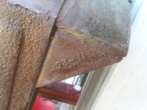
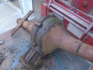
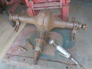
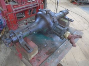
Starting to clean up the model-T rear axle and I think I found out what color the tractor was.

DSC06572.JPG


A wire brush in the die grinder is handy for getting the scaly rust off.

DSC06573.JPG


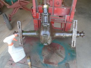
The axle is then sprayed down with a rust inhibitor.

DSC06574.JPG


I need to shorten the input shaft on the axle as much as I can so I can get it up as close as possible to the back of the transmission.
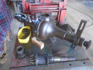
The parts for the input shaft are removed from the axle housing.

DSC06575.JPG


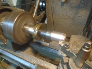
The back portion of the enclosed driveshaft housing is shortened about 1-1/2 inches and the outside is turned down so the grease seal cap will fit back onto it.

DSC06576.JPG


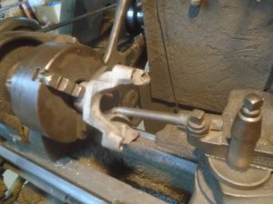
Then I cut the splines out of the center of a driveshaft yoke.

DSC06577.JPG


The input shaft is shortened about 6 inches and the end turned down to fit the driveshaft yoke.

DSC06579.JPG


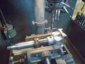
A hole is drilled thru the yoke and the shaft for a 3/8 allen bolt.

DSC06580.JPG


With everything re-assembled, the input shaft is about 9 inches shorter than it was.

DSC06582.JPG
 
Back
Top