Ford model-T tractor converson

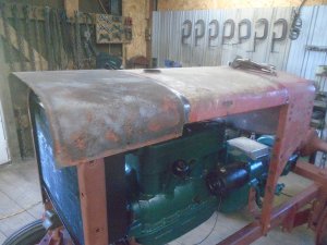
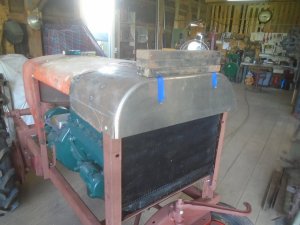
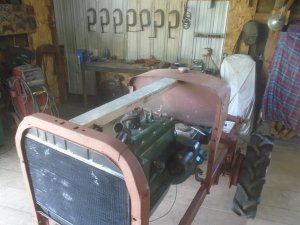
Starting on the hood. First thing is to set a piece of wood in between the gas tank and the radiator to support the metal while I fitting it in place.
The wood will be removed once the hood is finished.
DSC06806.JPG


The back piece is bolted onto the tank.
DSC06807.JPG


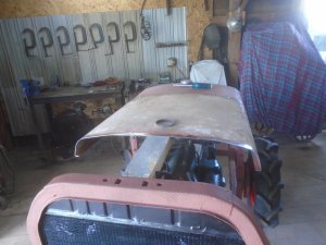
Unfortunately, I don't have a piece of sheet metal that is large enough to form the front part of the hood out of.
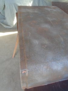
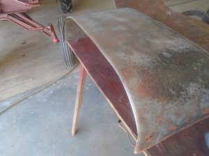
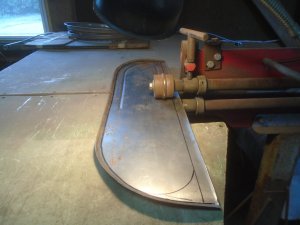
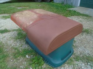
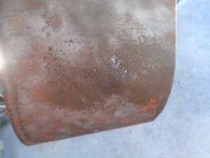
So I cut a 12 inch wide strip off the metal from the original hood. After sand blasting it, I found some spots that are rusted thru so that will have to be fixed.
DSC06809.JPG


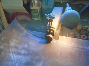
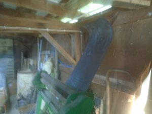
Forming the tight curve in the metal to match the curve on the back piece of the hood. ( a little glare from the sun shining in )
DSC06813.JPG


Checking the fit of the curve.

DSC06814.JPG


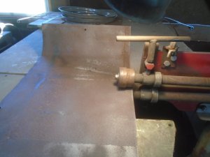
I'm using a set of step dies on the bead roller to form a stepped down lip along the back edge.
DSC06815.JPG


Here is the formed edge.

DSC06816.JPG


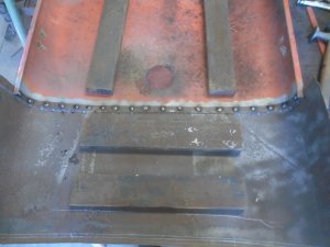
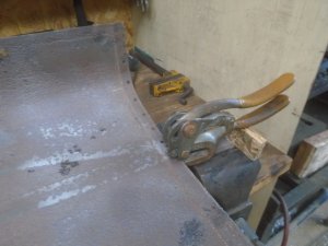
Then holes are punched into it for welding thru.
DSC06817.JPG


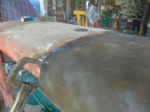
The stepped down lip fits underneath the the edge of the back part of the hood. This makes the surface of the two pieces flush to each other.
DSC06818.JPG


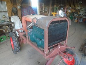
The front of the hood is formed around the larger curve of the radiator support. I'm thinking of forming a curved side panel at the front of the hood that would blend with the curve side panel on the gas tank.
DSC06820.JPG
 
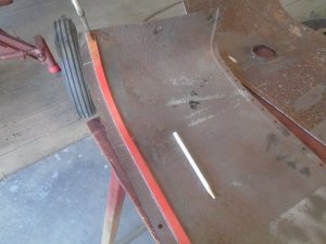
Using the plastic strip as a guide for drawing a straight line on the inside of the curved hood.

DSC06821.JPG


The edge is trimmed off at that line then it is run thru another roller that forms a half radius along the edge.

DSC06822.JPG


Here is the finished edge with the half round formed into it.

DSC06823.JPG


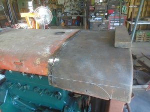
The front piece is set back in place and tack welded to the back piece of the hood.
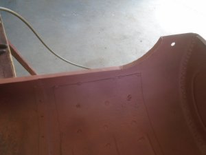
I've drawn a line on the side where it will be trimmed off later.

DSC06825.JPG


The two pieces are finish welded on the inside.

DSC06826.JPG


Forming the front panel and test fitting it.
This piece has the other half of the rounded edge formed into it where it fits up to the hood.

DSC06827.JPG


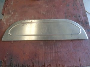
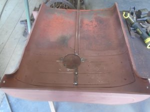
Once I'm satisfied with the fit, I turn it upside down and roll a bead into the center panel.

DSC06828.JPG


Here is the finished bead pattern.

DSC06829.JPG


This is then tack welded to the front of the hood.

DSC06830.JPG


It is finish welded on the inside and here is how it looks so far with the welds ground down and primed.

DSC06831.JPG
 
Last edited:
Working on shaping the sides of the front part of the hood.

DSC06832.JPG


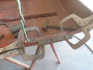
Two pieces of steel bar are clamped to either side and the lip is bent over to match the lip on the back part of the hood.

DSC06833.JPG


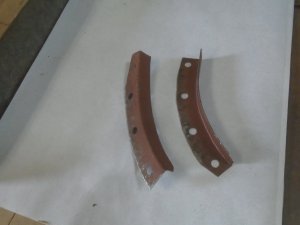
Then I formed two pieces for the lip on the curved area.

DSC06834.JPG


These are welded in place and the area is primed.

DSC06835.JPG


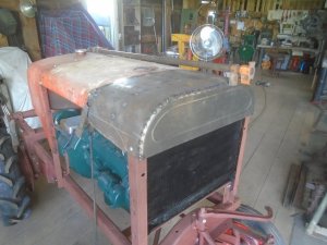
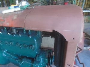
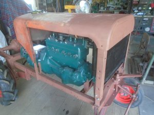
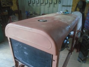
Here is how it looks back on the tractor.

DSC06836.JPG
 
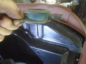
Originally, I had intended to use an elbow fitting and solder the radiator fill neck cup onto the back of the upper tank.
However, there isn't very much flat area on the back of the tank to solder the elbow to so that makes it much harder to get a good seal with the solder.
Also, I would be working really close to two other soldered joints. The top of the radiator core and the soldered seam along the top of the fan shroud.

DSC06850.JPG


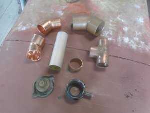
Here are the parts that I have to work with for fitting a radiator fill neck onto this radiator.
There are two 1-1/2 inch, 45 degree fittings. A 2 inch, 45 fitting and a 1-3/8, ' T ' fitting.

The radiator cap that I'm going to use does not have the rubber seal on it.
The model-A did not have a pressurized cooling system and I'm not sure if the water pump seals would hold pressure.
I'm figuring that the metal to metal fit on the radiator cap will hold very little, if any pressure at all.

DSC06851.JPG


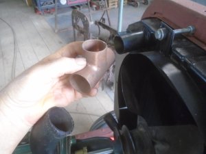
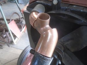
The water outlet fitting on the cylinder head is 2 inch OD and the fitting in the top of the radiator is only 1-1/2 inch OD so I'm going to have to make an adapter to go between these to fittings.
If I have to make an adapter anyway, why not put the ' T ' fitting in it for the fill neck ?

DSC06852.JPG


Lining up the pieces. One end is cut off the 2 inch fitting that will fit on top of the cylinder head.
This end will have to be heated up and hammered down to fit around the ' T ' fitting.

DSC06853.JPG


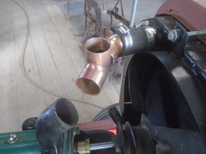
I made up a sleeve to fit inside the 1-1/2 inch fitting so the ' T ' fitting can then fit into it.
These two fittings are soldered together.

DSC06854.JPG


Then the top end of the 2 inch fitting is re-shaped to fit the ' T ' fitting and these two are then brazed together.

DSC06855.JPG

DSC06856.JPG


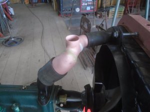
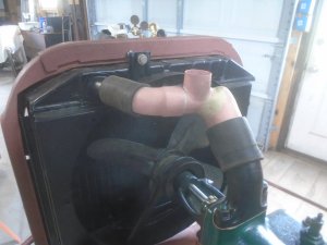
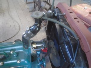
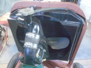
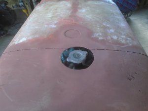
Here is the finished upper radiator hose and water fill fitting. The radiator cap will set just below the surface of the hood and be accessible thru a hole in the hood.

DSC06859.JPG

DSC06860.JPG
 
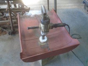
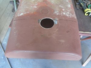
Cutting the hole in the hood for access to the radiator fill.

DSC06863.JPG

DSC06864.JPG


I hadn't planned on having a hole in this location when I welded in the center support on the inside of the hood and obviously I've had to remove part of that.
The metal on the front part of the hood is thinner than what the back part is so I have welded a second layer of metal with ribs rolled into it to the inside of the front part.
This makes the hood stiffer without actually needing that center support.

DSC06865.JPG


Here it is mounted on the tractor.

DSC06866.JPG

DSC06867.JPG
 
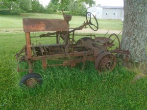
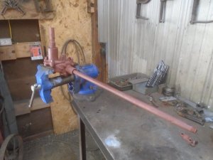
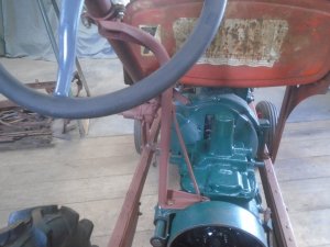
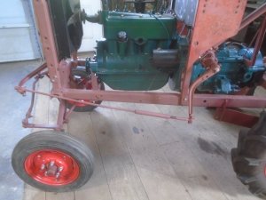
The steering is next. As you can see here, the steering box is located high off the frame and it is mounted in the center of the tractor with a long shaft going out to the steering arm.

9.JPG


I'm going to have the steering mounted over on the left side and the steering arm will then be closer to the steering box.
I've cut the steering arm shaft in two and you can see here that this arm is the same length as the steering arm on the front of the tractor.

DSC06871.JPG


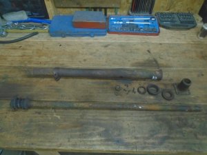
The steering wheel will not turn at all so I'm taking apart the whole assembly. The outer housing is removed from the steering shaft.

DSC06872.JPG


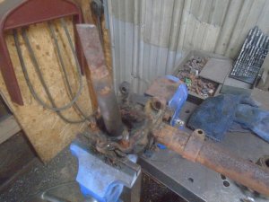
The steering shaft is removed and you can see what a mess everything is.

DSC06874.JPG


It took a brass punch and a 5 pound sledge to finally get the steering column shaft out of the housing.

DSC06875.JPG


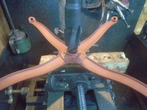
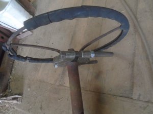
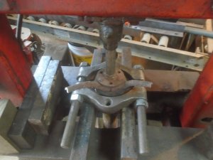
Now to get the steering wheel off. I've fit the press clamp around the bottom of the wheel.

DSC06876.JPG


The outer ring had to be cut off so this could fit into the press to remove the steering wheel from the column shaft.

DSC06877.JPG


The column is disassembled.

DSC06879.JPG


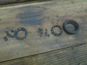
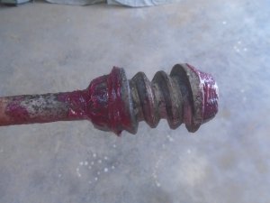
It looks lie the inner bearing races are machined onto the ends of the worm gear.

DSC06880.JPG


These are the parts for the two bearings in the gearbox and I'm going to have to clean them up and reuse them.

DSC06881.JPG
 
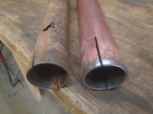
The steering column housing is in bad shape. I found a piece of pipe with the same inside diameter to replace it. The pipe is much thicker so that will make the steering column even stronger.

DSC06887.JPG


The bearings cleaned up fairly good. They are re-assembled onto the ends of the worm gear on the steering column shaft.

DSC06888.JPG


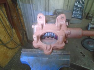
The steering column shaft is then assembled into the steering box.

DSC06889.JPG


Then the steering output shaft is bolted in place on the box. This shaft is still the length that I had cut it off at. Once I get the steering arm mounted, then the shaft can be trimmed down.

DSC06890.JPG


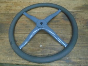
I'm going to use an old Ford model-T steering wheel on this. The wheel has been welded on in the center so no one is going to want it to put on a car.
With the weld repair, this is exactly the type of used steering wheel that would have been used on a tractor like this. It will be perfect.
However, the hole in the model-T wheel is a straight 3/4 inch diameter hole and the steering shaft takes a wheel with a tapered hole. The model-T wheel just slides down onto the steering shaft.

DSC06892.JPG


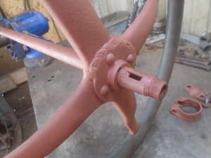
I'm going to have to take the center hub out of the original steering wheel and fit it into the model-T wheel.

DSC06893.JPG


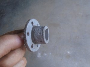
Here is the hub out of the original wheel.

DSC06894.JPG


I'm using a counterbore tool with a 3/4 pilot to bore out the center of the steering wheel.

DSC06895.JPG


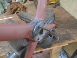
The original hub is pressed into the hole in the model -T wheel. Three 1/4-20 holes are drilled and tapped into the model -T wheel. A piece of threaded rod is screwed into a hole until it is flush with the back of the wheel. This is then cut off flush with the front face. The same thing is done with the other two threaded holes in the hub

DSC06898.JPG


These holes are brazed over on the front and the other three holes are filled with braze. The braze is ground down smooth with the front flange. It is painted and re-assembled onto the steering wheel ring.

DSC06899.JPG
 
Last edited:
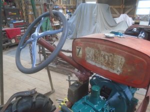
The steering wheel is hanging from the hoist and the steering box is resting on wood blocks for positioning it in place.

DSC06903.JPG


Forming the pieces for the steering box mount and tack welding them together.

DSC06904.JPG


The mount is all welded up and everything is bolted back in place.

DSC06906.JPG

DSC06907.JPG


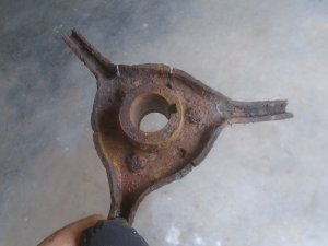
This is the original steering column support bracket. It is made out of pieces of a model-T running board bracket that are welded together.
I'm going to modify it a little and re-use it to support the steering column.

DSC06908.JPG


The " U-shape " bottom bracket that the column fits into is actually the upper clamp for the front motor mount off a model-T
They drilled a hole in the center and welded a bolt onto it for attaching it to the support bracket.

DSC06914.JPG


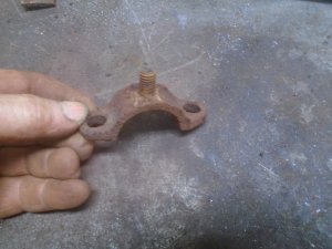
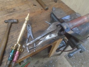
Making the upper clamp to go on the steering column by heating a piece of strap steel and forming it around a pipe.

DSC06915.JPG


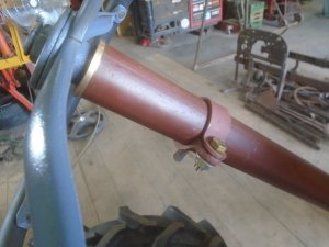
Here is the finished clamp.

DSC06916.JPG


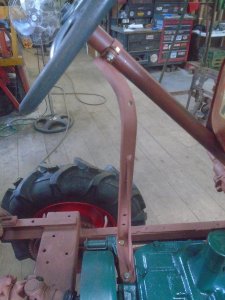
The steering column support is finish and mounted in place.

DSC06917.JPG

DSC06918.JPG
 
With the steering box mounted in place, I can now figure out just how the steering arm will fit.
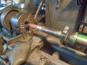
Here I'm turning down the area of the pinion shaft for the arm to fit onto it.

DSC06921.JPG


The excess part of the shaft is cut off and the arm it mounted onto it.

DSC06922.JPG


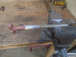
The drag link need to be extended about 7 inches. I've cut off the one end and have turned down a piece of 5/8 threaded rod to fit into it.

DSC06923.JPG


The threaded rod is brazed and I'm going to drill and tap one end of the piece of 7/8 diameter steel rod to screw onto it.

DSC06924.JPG


the other end of the 7/8 steel rod is drilled out to fit over the drag link. This is welded onto it and then it is primed.
NOTE .. the curve in the drag link.
DSC06925.JPG


The drag link is mounted in place to complete the steering.
DSC06927.JPG


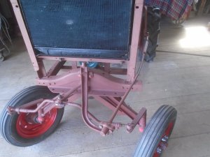
This is why there is a curve in the drag link. It allows the wheels to be turned to the right a little more.

DSC06926.JPG


If I had built this tractor myself, I certainly wouldn't have used this style of steering.
I would have had a pitman arm extending straight out about 6 inches from the front of the tractor.
Then I would have mounted a bell-crank with 6 inch arms on the front corner of the frame with one arm pointing forward and the other arm pointing out to the side.
The drag link from the steering box would have attached to the arm on the bell-crank sticking out to the side.
Another drag link would go from the forward arm on the bell-crank to the steering arm in the center.
This would allow the front wheels to be able to turn even farther then they are able to now without having to have a bend in the drag link.

However, the tractor was built with these extra long pitman arms on the front and on the steering box with just the one drag link. It is noticeably a part of the original design so I want to keep it if I can.
 
Last edited:
Watching you work on your projects makes me even more certain that in a few years I will stop, or at least severely cut back working on other people's stuff so that I can finally find time and energy to return to my own projects that have had to be moth-balled the last several years.
 
Steering ki
With the steering box mounted in place, I can now figure out just how the steering arm will fit.
Here I'm turning down the area of the pinion shaft for the arm to fit onto it.

View attachment 56566


The excess part of the shaft is cut off and the arm it mounted onto it.

View attachment 56567


The drag link need to be extended about 7 inches. I've cut off the one end and have turned down a piece of 5/8 threaded rod to fit into it.

View attachment 56568


The threaded rod is brazed and I'm going to drill and tap one end of the piece of 7/8 diameter steel rod to screw onto it.

View attachment 56569


the other end of the 7/8 steel rod is drilled out to fit over the drag link. This is welded onto it and then it is primed.
NOTE .. the curve in the drag link.

View attachment 56570


The drag link is mounted in place to complete the steering.

View attachment 56571


This is why there is a curve in the drag link. It allows the wheels to be turned to the right a little more.

View attachment 56572


If I had built this tractor myself, I certainly wouldn't have used this style of steering.
I would have had a pitman arm extending straight out about 6 inches from the front of the tractor.
Then I would have mounted a bell-crank with 6 inch arms on the front corner of the frame with one arm pointing forward and the other arm pointing out to the side.
The drag link from the steering box would have attached to the arm on the bell-crank sticking out to the side.
Another drag link would go from the forward arm on the bell-crank to the steering arm in the center.
This would allow the front wheels to be able to turn even farther then they are able to now without having to have a bend in the drag link.

However, the tractor was built with these extra long pitman arms on the front and on the steering box with just the one drag link. It is noticeably a part of the original design so I want to keep it if I can.
Kind of reminds me of the old Case CC, DC, SC and V series with the "fence cutter" or "chicken roost" steering.
 
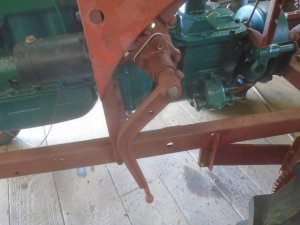
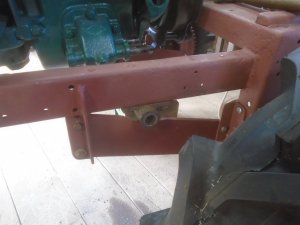
The mount for the pivot shaft for the brake and clutch pedals is bolted to the underside of the frame.

DSC06929.JPG


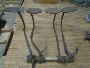
I'm using model-A pedals and they had to be straightened out to fit the tractor.
The stock model-A pedals are on the left and the modified pedals are on the right.

DSC06930.JPG


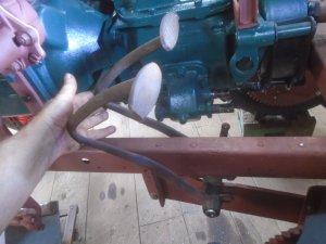
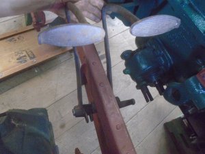
Here's how the look on the tractor.

DSC06932.JPG

DSC06933.JPG


On a side note. ........
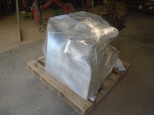
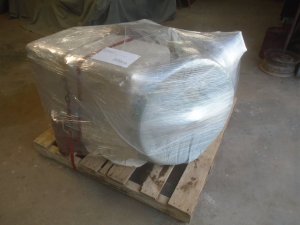
Remember the Simplex Servi-Cycle that I built to put up for sale ?
Here it is all packed up and ready to be shipped out to Seattle Washington tomorrow.

DSC06934.JPG

DSC06935.JPG
 
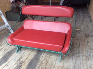
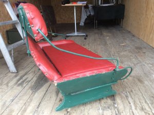
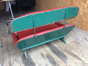
I have been hunting for a buggy seat for the tractor about two months now.
Any that I could afford their asking price have been so far away that the shipping cost was outrages.
The ones that were close enough for me to go pick up have all been priced too high to start with.

This one just showed up on ebay today with the asking price that I can afford and it is located only about 60 miles from where my daughter lives in Ohio.
She just bought it for me and will bring it with her the next time she comes down for a visit.

seat.jpg

seat-2.jpg

seat-3.jpg
 
Back
Top