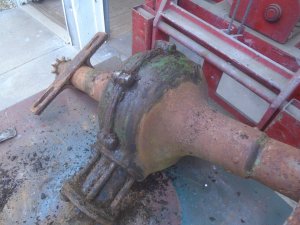
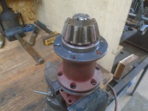
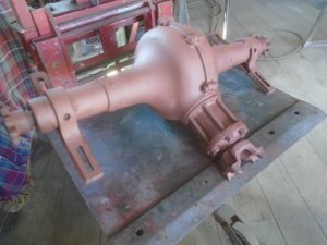
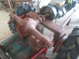
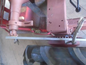
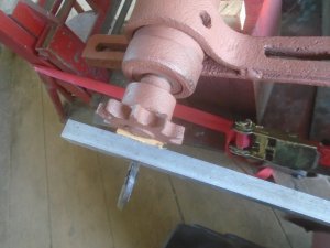
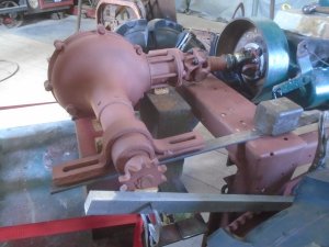
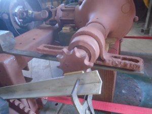
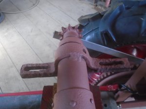
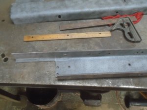
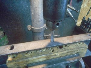
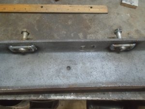
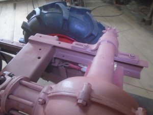
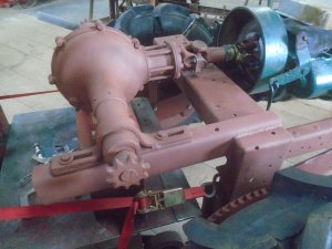
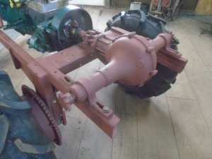
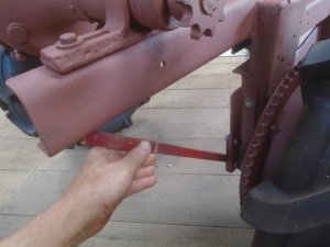
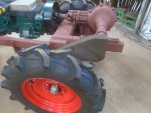
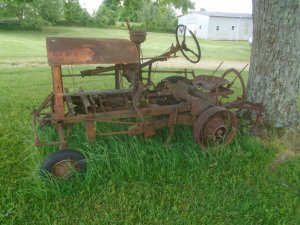
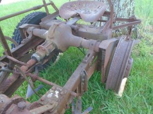
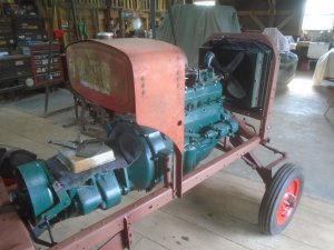
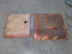
The model-T has a driveshaft housing with the driveshaft rotating around inside it.
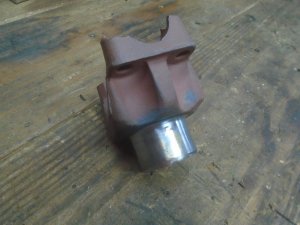
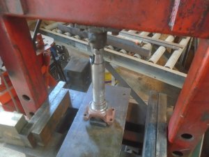
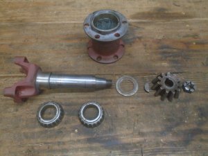
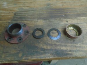
At the rear axle, there is a large roller bearing that fits inside a bearing housing and rides on a case hardened sleeve that fits onto the driveshaft.
There is a thrust bearing in front of this roller bearing.
The pinion gear fits onto the end and is held on with a nut.
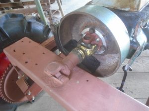
The driveshaft is pinned into the U-joint on the back of the transmission to hold it up against the thrust bearing.
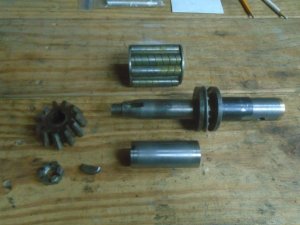
While putting this cut off section of the drive shaft together, I realized that there is nothing to hold it up against the thrust bearing. When the tractor isn't running, this input shaft can move in and out and it is only pushed up against the thrust bearing by the force of the ring and pinion gears meshing together at the angle.
The model-T relies on the long driveshaft being held in the U-joint on one end and the roller bearing on the other to keep it from wobbling.
With the short input shaft being held only by the roller bearing, there is enough slop so the shaft can wobble around a little along with being able to move in and out.
So I have decided to re-engineer this input shaft assembly.
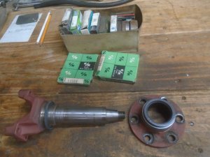
1960 Chevy front inner wheel bearings are just the right size to fit snugly over the hardened sleeve.
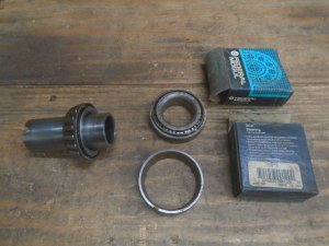
The outer race on these bearings are a little smaller than the bore in the model-T bearing housing.
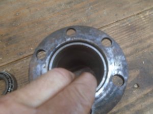
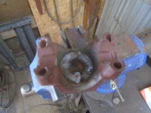
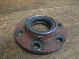
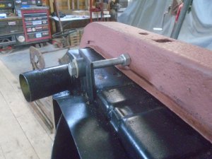
I made up a sleeve out of a piece of pipe that is pressed down into the bearing housing.
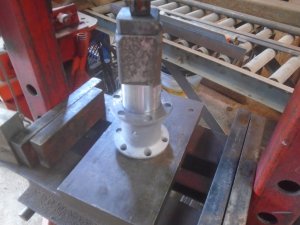
It is then welded thru two holes in the housing to make sure that it never moves.
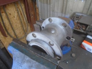
Then I put it on the lathe and start machining the counterbores for the Chevy outer bearing races.
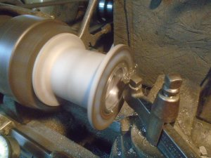
The Chevy wheel bearings now fit into each end of the housing.
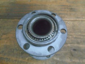
The thrust washer is removed from the input shaft and a piece of steel tube is put on there in it's place.
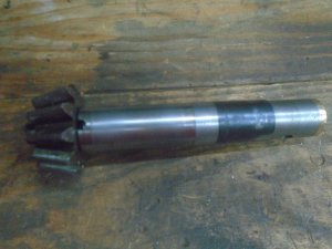
The input shaft in now supported by two tapered roller bearings.
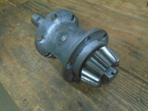
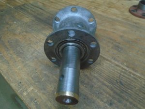
At the rear axle, there is a large roller bearing that fits inside a bearing housing and rides on a case hardened sleeve that fits onto the driveshaft.
There is a thrust bearing in front of this roller bearing.
The pinion gear fits onto the end and is held on with a nut.
The driveshaft is pinned into the U-joint on the back of the transmission to hold it up against the thrust bearing.

While putting this cut off section of the drive shaft together, I realized that there is nothing to hold it up against the thrust bearing. When the tractor isn't running, this input shaft can move in and out and it is only pushed up against the thrust bearing by the force of the ring and pinion gears meshing together at the angle.
The model-T relies on the long driveshaft being held in the U-joint on one end and the roller bearing on the other to keep it from wobbling.
With the short input shaft being held only by the roller bearing, there is enough slop so the shaft can wobble around a little along with being able to move in and out.
So I have decided to re-engineer this input shaft assembly.
1960 Chevy front inner wheel bearings are just the right size to fit snugly over the hardened sleeve.

The outer race on these bearings are a little smaller than the bore in the model-T bearing housing.

I made up a sleeve out of a piece of pipe that is pressed down into the bearing housing.

It is then welded thru two holes in the housing to make sure that it never moves.

Then I put it on the lathe and start machining the counterbores for the Chevy outer bearing races.

The Chevy wheel bearings now fit into each end of the housing.

The thrust washer is removed from the input shaft and a piece of steel tube is put on there in it's place.

The input shaft in now supported by two tapered roller bearings.


Last edited:

