Ford model-T tractor converson

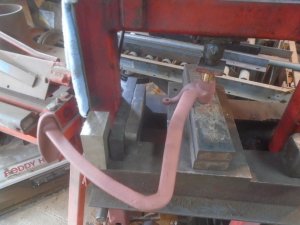
I pressed in new bushings in both pedals.
DSC06942.JPG


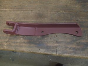
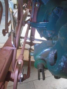
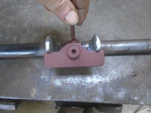
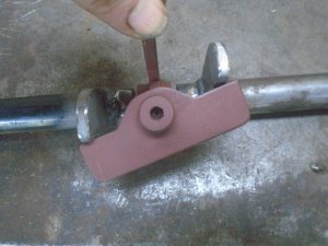
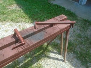
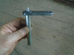
This is the outside lever for the cross shaft on the clutch linkage.
DSC06944.JPG


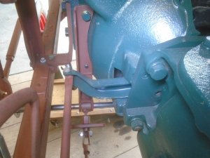
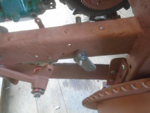
It fits into the pivot bracket that is mounted thru the frame.
DSC06945.JPG


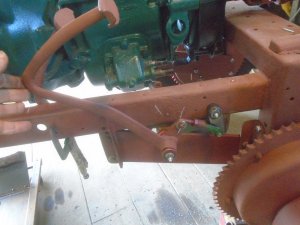
A short linkage rod connects it to the clutch pedal.
DSC06946.JPG


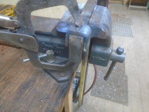
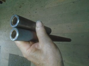
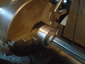
I did not have a piece of round stock large enough for what I need to make the hub for the lever on the inside of the cross shaft. So I turned down two pieces of pipe so they fit inside each other. Then I fit them over a piece of 1 inch bar stock.
I drilled a hole down thru the pieces and pressed a pin into it with the outside of the pin braised on both ends.
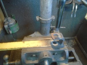
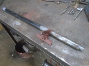
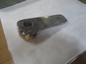
The center is drilled out and reamed to fit onto the cross shaft.
DSC06949.JPG


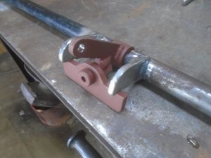
The lever is pressed onto the hub and welded in place.
DSC06950.JPG


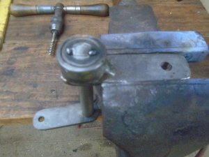
this is positioned on the crass shaft and a spot of weld holds everything together. Then I drilled and tapped a 5/16-18 threaded hole so half of it is on the crass shaft and the other half is on the hub.
With a set screw threaded into the hole, it is just like a key to keep the hub from rotating around the cross shaft and the threads keep it from sliding along the shaft.
DSC06951.JPG


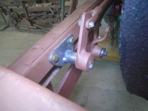
The cross shaft is mounted back in place and a square head set screw is tightened down into the 5/16 threaded hole.
DSC06952.JPG


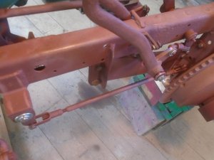
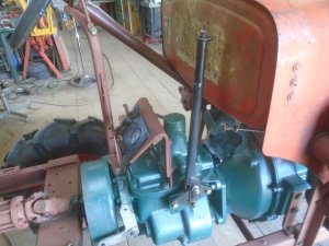
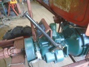
The linkage arm is then made up to go from the inside lever up to the clutch throw-out arm.
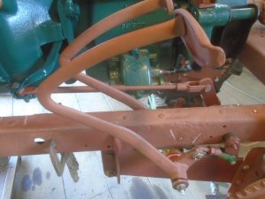
This is the position of the pedal with the clutch engaged.
DSC06954.JPG


And with the clutch arm pulled all the way back as far as it will go.
The clutch pedal will only have to move about two thirds of this distance for the clutch to work.
DSC06955.JPG
 
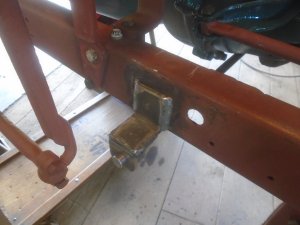
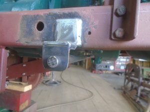
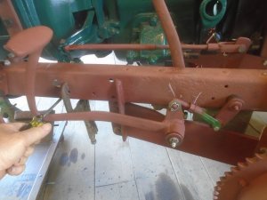
Brakes are next. I've made up two " Z " shaped brackets for holding the 5/8 diameter steel rod that the brake rocker shafts will pivot on.
One bracket is welded onto the left side of the frame.

DSC06957.JPG


And the other is welded to the right side with the 5/8 rod extending between them.

DSC06958.JPG


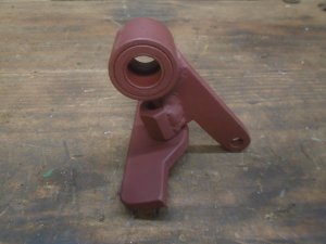
These are the parts for the equalizing lever that will allow the same pressure to be applied to each brake.

DSC06959.JPG


This is how it looks when all assembled together.

DSC06961.JPG


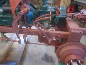
Forming a " U " shape support bracket of flat stock.
DSC06962.JPG


Drilling and reaming a 5/8 diameter hole thru both sides.
DSC06963.JPG


The long side of the bracket is cut off and a piece of angle iron is fit to it that will bolt up to the bellhousing on the engine.

DSC06964.JPG


With this bracket bolted to the bellhousing, the 5/8 diameter rod is supported by the two holes in the sides of the " U " shape bracket with the equalizer lever mounted between them.

DSC06965.JPG


The brake rod is mounted to the lever on one end with the other end mounted to the lever on the brake pedal ( under the clutch throw-out rod ).

DSC06966.JPG
 
Two sleeves are made up from 1 inch OD steel tube with brass bushings in each end.

DSC06972.JPG


they are assembled on the 5/8 rod with the equalizer lever in between them to make up the cross shaft assembly for the brakes

DSC06975.JPG


A lever is welded onto each tube that rides up against the cross bar on the equalizer lever.

DSC06976.JPG


This is the position of the levers with the movement being the same on both brakes.

DSC06977.JPG


This shows how the crossbar will maintain equal pressure on both levers even if one side has to move more than the other.

DSC06978.JPG


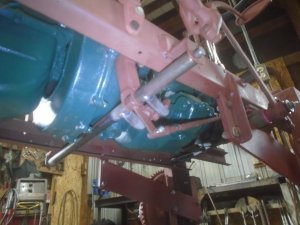
The assembly is mounted back up under the tractor.
I've ordered some 3/8-24 fine threaded rod for using on the brake rods going back to the wheels so I won't be able to finish hooking up the brakes until it comes in.

DSC06979.JPG
 
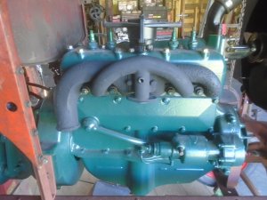
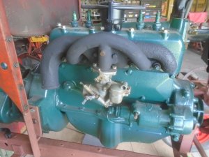
While I'm waiting for parts .. I've mounted the manifold on the engine.

DSC06980.JPG


And the carburetor.

DSC06981.JPG


the exhaust is fixed up with w U-shape pipe so it points straight up.

DSC07001.JPG


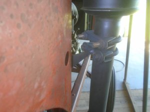
There is a bracket bolted to the gas tank frame that supports the outer part of the exhaust pipe.
I don't want to use a flapper rain cap on this exhaust so the bottom of the U-shape pipe has a 1/8 diameter hole drilled into it so any water that gets in on a rainy day can drain back out.

DSC07002.JPG


Here you can see how the support bracket is welded to the pipe clamp.

DSC07007.JPG


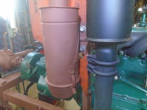
This air cleaner housing is off a Alis Chalmers tractor.
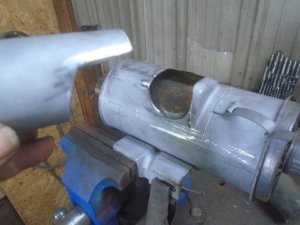
I cut the outlet pipe off that came straight out from the side of the housing

DSC07008.JPG


The hole in the housing is cut out farther and a piece of pipe is trimmed to fit into it so the outlet will come out at a 90 degree angle from what it use to.

DSC07009.JPG


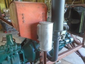
The new outlet pipe is welded onto the side of the housing and the finished air cleaner is mounted onto the tractor.

DSC07010.JPG


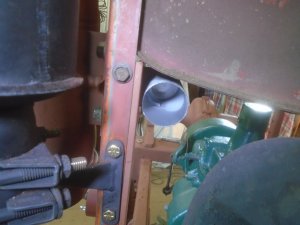
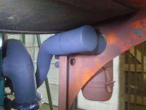
The outlet pipe now comes out under the gas tank.

DSC07011.JPG


The air cleaner is fastened to the side of the gas tank shroud with two bolts.

DSC07012.JPG
 
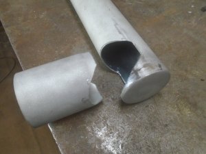
Working on the intake air tube that will go down to the carburetor. I used a freeze plug to cap one end on a piece of exhaust pipe.
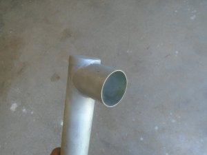
Then I cut a notch in it and also in another piece of pipe so they will fit together.

DSC07017.JPG


The two pieces are welded together.

DSC07018.JPG


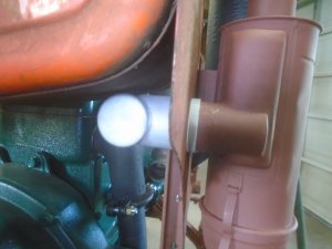
this fits over the outlet pipe on the air cleaner.

DSC07019.JPG


the open end is flush with the front of the gas tank.

DSC07020.JPG


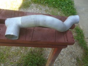
Using a couple of elbows, I formed up the rest of the pipe that goes down to the carburetor. The one end is larger so it slides over the piece that fits onto the air cleaner.

DSC07021.JPG


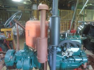
The finished air pipe is mounted in place.

DSC07023.JPG


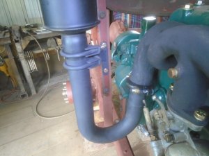
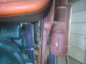
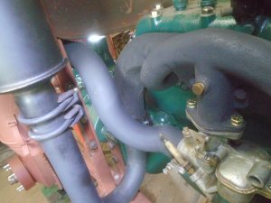
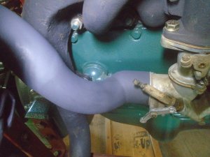
The lower end slips onto the carburetor.

DSC07024.JPG


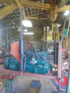
Here's how it looks when fit together under under the gas tank.

DSC07025.JPG
 
The parts came in to finish the brakes.
The levers are welded on the outside of the two cross shafts.

DSC07035.JPG


The crass shafts are mounted back under the tractor and the rods are made up to go back to the brake levers on the rear hubs.

DSC07037.JPG


With both the clutch and brakes hooked up, the two pedals are adjusted so the are even with each other.

DSC07036.JPG
 
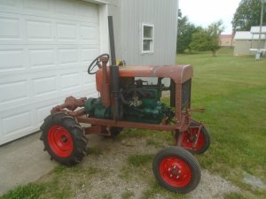
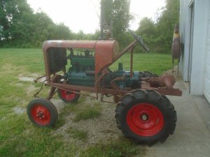
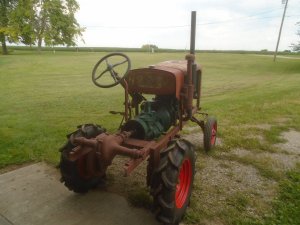
It's hard to get a clear view of how a project is looking while it is still in the garage with all the stuff scattered around it. I like to put it outside once in awhile just to make sure that everything is blending together alright.

If I need to make any changes in the design, it's a lot easier to do that now than after everything is completely finished.
I'm pleased with how it sits so the work will continue on schedule.

DSC07040.JPG

DSC07041.JPG

DSC07043.JPG
 
Like the earlier Ford model-T, the 1928 thru 1931 Ford model-A had finger levers on the steering column for operating the spark advance and the throttle.
The model-A also had a foot pedal for the throttle ( the model-T did not have a foot pedal ).

I have a Model-T steering column that I had thought of using on this tractor but it would have to be shortened a lot.
The model-T has planetary reduction gears right under the steering wheel. model-T steering.jpg

The gear reduction would be increased if the column is hooked to a regular steering box. This would make it so the steering wheel would have to be rotated completely around a lot in order to turn the tractor.

I decided that rather than destroy a good model-T steering column, I would just make my own column and attach it to the original gear box on the tractor so it would steer with the normal amount of steering wheel rotations.

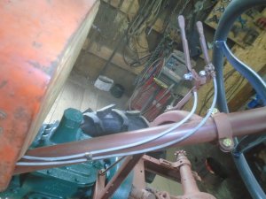
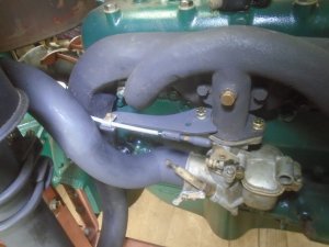
So that brings me to the problem of making the spark advance and throttle linkage. I could make the two levers that go on the side of the steering column, like on the model-T and the model-A, but that would take a lot of effort and because of the location of the steering in relation to the engine, it would take some fancy linkage.
The simplest solution is to use cable linkage on both of them.

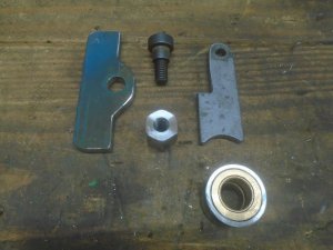
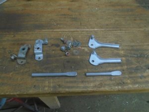
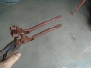
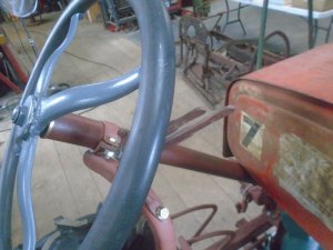
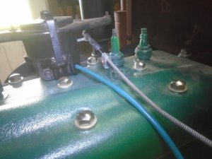
These are the disassembled parts for two universal throttle cable levers. Throttle cable levers like these were available back when this tractor was first built.
There are also two pieces of steel rod with one end flattened.

DSC07044.JPG


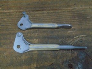
Those rods are brazed onto the lever arms.

DSC07045.JPG


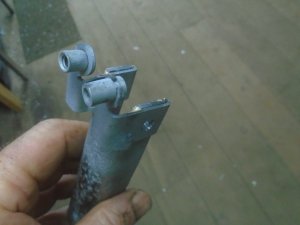
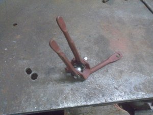
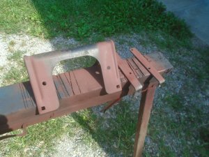
The mounting brackets for the levers are trimmed down and brazed onto a piece of steel channel ( the steel channel is part of a model-T running board bracket ).

DSC07046.JPG


The levers are bolted onto the brackets and the lower part of the steel channel is cut off.
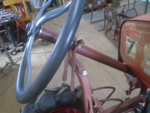
This gives me a pair of finger control levers that look correct for the year range of the tractor.
The short lever is for the spark control and the longer one is the throttle.

DSC07047.JPG


A piece of steel rod with a hole in one end is welded to it.

DSC07048.JPG


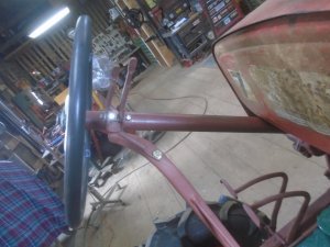
This bolts onto the steering column support bracket.

DSC07049.JPG

DSC07049-1.JPG


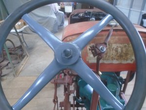
The end of the short lever is flush with the outside of the steering wheel and the longer one extends out past the steering wheel a little.
This is the position with both levers fully retarded.

DSC07050.JPG


And this is with them fully advanced.

DSC07051.JPG
 
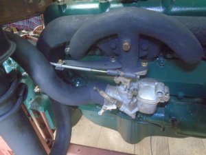
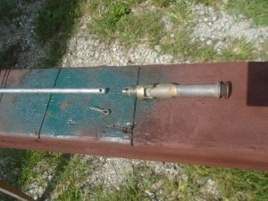
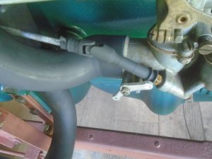
I went down to TSC and bought a 1/4 drive universal.
This is brazed onto the end of the choke / mixture control sleeve.
Then I took a 3/16 socket and drilled it out to a 1/4 inch hole. This socket is brazed onto the other end of the universal.
The end of the choke / mixture control rod fits into the drilled out socket and is held in place with a cotter pin.

DSC07058.JPG


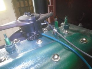
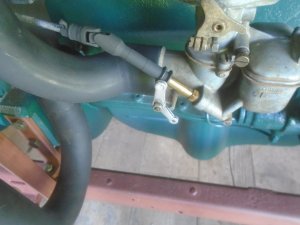
The choke / mixture control rod is mounted to the underside of the gas tank on a bracket with a nylon bushing in it.

DSC07059.JPG


The knob is rotated to adjust the fuel mixture.

DSC07059-1.JPG


The rod then rotates the sleeve on the carburetor.

DSC07060.JPG


When the choke is pulled out. ...

DSC07061.JPG


It then pulls the sleeve up on the carburetor to close the choke.

DSC07062.JPG
 
I went down to TSC and bought a 1/4 drive universal.
This is brazed onto the end of the choke / mixture control sleeve.
Then I took a 3/16 socket and drilled it out to a 1/4 inch hole. This socket is brazed onto the other end of the universal.
The end of the choke / mixture control rod fits into the drilled out socket and is held in place with a cotter pin.

View attachment 57672


The choke / mixture control rod is mounted to the underside of the gas tank on a bracket with a nylon bushing in it.

View attachment 57673


The knob is rotated to adjust the fuel mixture.

View attachment 57674


The rod then rotates the sleeve on the carburetor.

View attachment 57675


When the choke is pulled out. ...

View attachment 57676


It then pulls the sleeve up on the carburetor to close the choke.

View attachment 57677
Beyond my understanding!
 
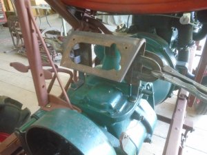
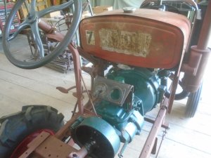
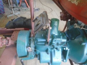
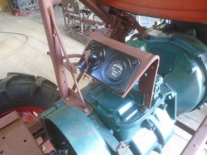
I'm using a dash panel that came on the Ford model-T trucks with the wood cab and I'm making two brackets to mount it onto the top of the transmission.

DSC07064.JPG


This is the back of the panel and the two mounting brackets. They are primed before there bolted together.

DSC07065.JPG


Checking to see how it will look with the switch plate mounted on the dash panel.

DSC07066.JPG

DSC07068.JPG


The switch plate is painted and fastened onto the primed dash panel.

DSC07071.JPG


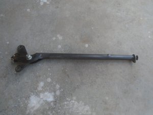
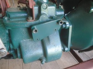
I have a model-A hand brake lever that needs to mount onto the side of this Chevy truck transmission to operate the parking brake.

DSC07072.JPG


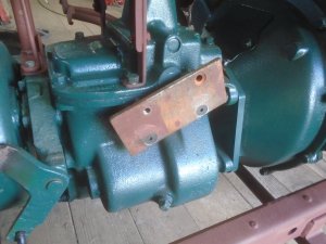
Mounting a 1/4 inch thick steel plate onto the side of the transmission. This will be the adapter plate for the hand brake lever.

DSC07074.JPG


The finished adapter plate.

DSC07075.JPG


The model-A hand brake lever is bolted onto the adapter plate. This is the full forward position.

DSC07076.JPG


And this is the position of the lever when pulled all the way back.

DSC07077.JPG
 
Crazy , crazy amount of work you're putting into this . I mean that in a good way...
Your work is going to have the average guy not appreciating the amount of time and skill you have in this.. Incredible work..!
 
Back
Top