Ford model-T tractor converson

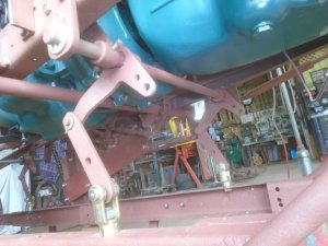
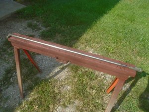
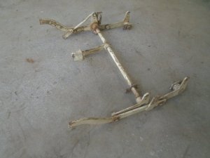
This is the lift assembly off a garden tractor. I have no idea what tractor it came from.
DSC07154.JPG


The only parts that I'm interested in are the four angle lift brackets.
DSC07155.JPG


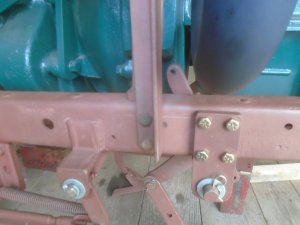
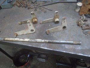
Four mounting brackets are made up and bolted to the side of the tractor frame, two on the front and two on the back. Then a 3/4 inch steel rod is slid in place between them.
DSC07156.JPG


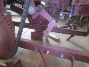
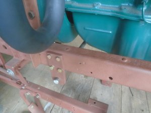
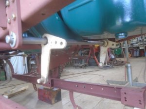
The angle lift brackets are slid onto the 3/4 rods.
DSC07157.JPG


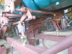
This gives me a lifting bracket on each corner of the frame.
DSC07158.JPG


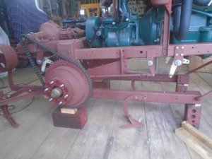
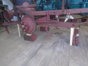
The cultivator frame is raised up to its maximum height and set on blocks of wood.
DSC07159.JPG


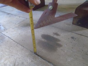
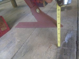
This lifts the cultivators up a little more than 5 inches off the ground.
DSC07160.JPG


With the cultivator frame raised up, there is still plenty of room around the flat belt pulley.
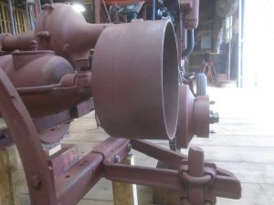
DSC07161.JPG


When the cultivator frame is raised up, the the angled support bracket on the front swings up and this moves the frame back about 3 inches.
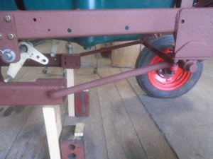
DSC07162.JPG


This increases the clearance between the rear arch support and the pulley housing.
This also maintains the clearance between the rear cultivators and the rear tires as the cultivators move up and back to fallow the curve of the tire.
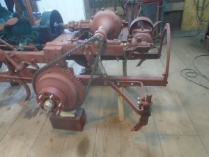
DSC07164.JPG
 
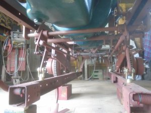
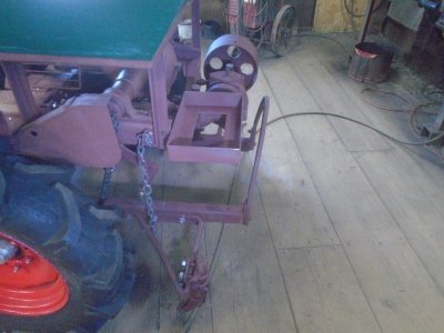
Lifting brackets are bolted to the top of the cultivator frame and strap hangers are fastened to them and the lifting arms up on the tractor frame.
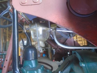
This is the front lifting arm assembly and the angled lifting arms are fastened solid to the cross shaft.
DSC07167.JPG


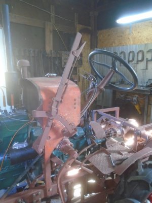
this lever sticking up above the tractor frame is what the operating lever will be attached to for raising and lowering the cultivator frame.

DSC07168.JPG


These are the two rear lifting arms.

DSC07169.JPG


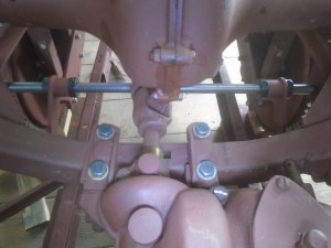
The two lifting arms on the rear are not fastened to the cross shaft. They each can rotate independently on the cross shaft. They are held in place by a round collar that is clamped to the cross shaft on either side of the lifting arms.
Each of these two arms will be operated by a rod coming back from the front lifting arm on each side. Because these two arms can vary in their movement, this will keep the lifting assembly from binding as it is being raised and lowered.

DSC07170.JPG


This is one of the operating rods that will fit between the two lifting arms on one side of the frame.
Because it will operate in a pushing motion instead of a pulling motion, it is made out of a piece of 5/8 diameter solid steel rod.

DSC07171.JPG


The two rods for operating the rear lifting arms are mounted in place.

DSC07172.JPG

DSC07173.JPG


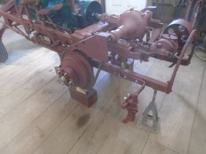
I have lifted the back of the cultivator frame up and it is resting on just one jack stand. The lifting arm assembly keeps all four corners of the frame up at the same level.

DSC07176.JPG


With this finished. it has gained 3/4 inch of clearance.

DSC07177.JPG


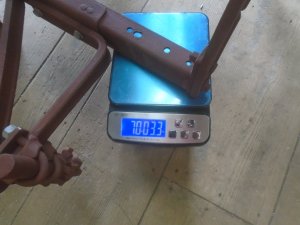
The whole cultivator frame assemble only weighs 70 pounds.

DSC07178.JPG
 
Got to thinking about how to control the depth of the cultivators. The lift control lever for raising and lowering it will have notches to hold the lever in different positions but I didn't like the idea of the digging force being put on the all the different parts of the lift assembly.
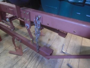
So I decided to put a chain depth guide on each of the four corners.

DSC07179.JPG


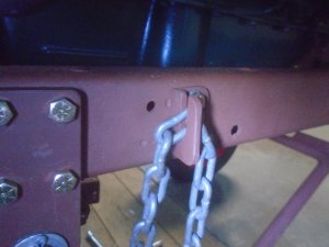
The chain slips into a slot on the upper bracket. By setting the different links into the slot, the depth can be lowered in one inch increments down to four inches deep. Having a depth chain on each corner will keep the cultivator frame level at whatever depth it is set to.
Instead of having the lift control lever lock into a notch when the cultivators are lowered, I'll make it so it floats in that position and the four chains will control the depth.

DSC07180.JPG
 
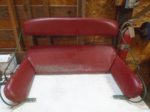
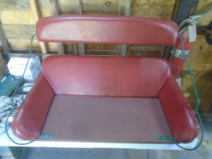
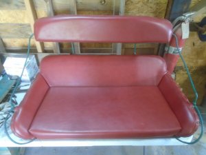
My daughter came down to visit this weekend and she brought the buggy seat with her.
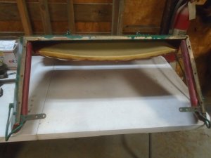
There is a rotted out area on one corner of the wooden base so I have removed the whole thing.

DSC07185.JPG


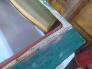
The edges of the rest of the wood frame looks to be in mostly good condition.

DSC07184.JPG


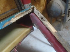
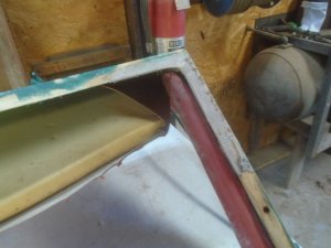
There is a little rot on this back corner which will have to be repaired.

DSC07183.JPG


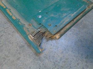
Here is the matching corner on the wood base that is rotted out bad. I'm going to replace the whole base board.

DSC07182.JPG
 
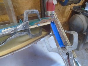
The rotted wood is trimmed out around the corner and pieces of thin cardboard are taped to the inside and outside of the wood frame. Then pieces of wood are clamped in place to support the cardboard.
The area is filled with a mixture of fiberglass resin mixed with sawdust.

DSC07186.JPG


Once that has hardened, it is smoothed down.

DSC07187.JPG

DSC07188.JPG


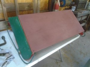
The new wood bottom panel is glued in place and fastened with screws at the corners.

DSC07189.JPG

DSC07191.JPG


The padded seat bottom is re-installed.

DSC07193.JPG
 
I haven't been able to post on this forum for awhile. Now that I can again, there is some catching up to do.
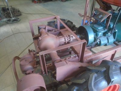
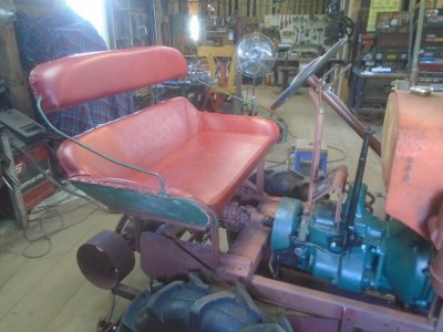
A angle iron frame is made up on the back of the tractor.

DSC07198.JPG


The seat bolts to this frame.

DSC07201.JPG


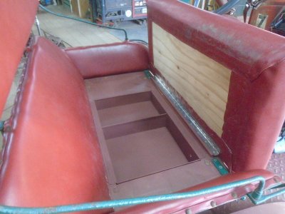
There is a storage box under the seat.

DSC07296.JPG


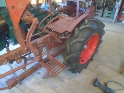
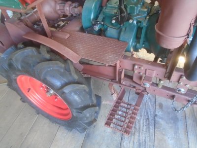
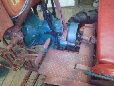
The foot plate with a little fender and a step are mounted on both sides.

DSC07221.JPG

DSC07266.JPG


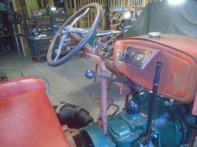
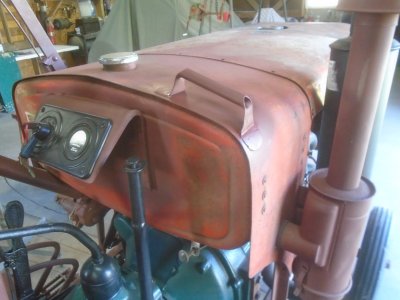
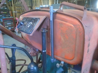
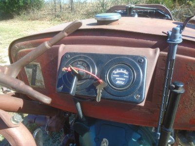
The dash panel has been moved up onto the back of the gas tank.

DSC07225.JPG


A handle is mounted on top of the gas tank on the right side to help passengers to get on and off.

DSC07267.JPG


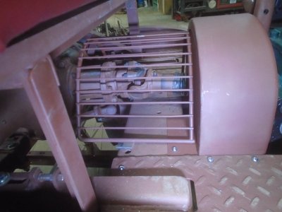
The brake drum on the back of the transmission and the driveshaft have a guard over them.

DSC07286.JPG


The battery box is mounted behind the seat.

DSC07291.JPG


This is the lever to operate the PTO on the side of the transmission that powers the flat belt pulley on the back.

DSC07254.JPG
 
A lever is mounted on the left side of the gas tank to raise and lower the cultivator frame. This operates easily with just one hand.

DSC07398.JPG


The gas gauge tube is mounted on the back of the gas tank.

DSC07325.JPG


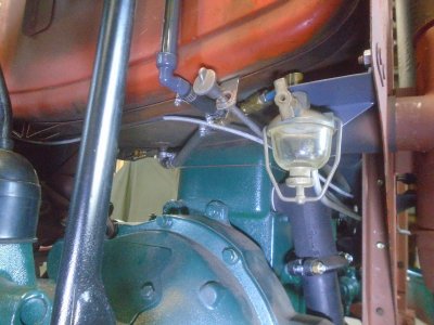
The fuel bowl with the shut-off valve is mounted down on the right side under the tank.

DSC07326.JPG


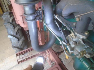
A steel fuel line runs from the fuel bowl out to the carb.

DSC07322.JPG

DSC07320.JPG


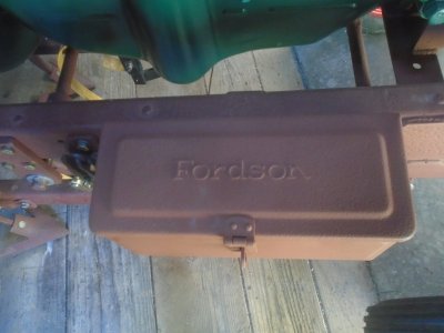
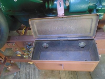
An old Fordson tool box is mounted on the frame.

DSC07303.JPG

DSC07304.JPG


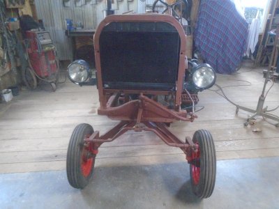
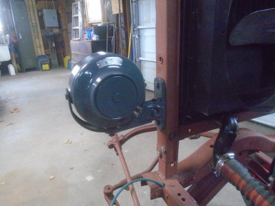
The headlights are mounted in place.

DSC07356.JPG

DSC07359.JPG


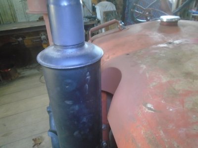
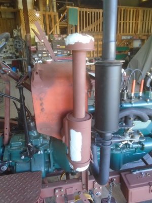
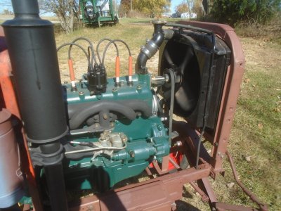
The side of the hood is notched out for clearance around the muffler.

DSC07375.JPG
 
I have changed my mind on the electrics. Originally I had intended to stay with the 6-volt system that the Ford model-A had. However, if you go to any antique tractor show you will find that most of the old tractors have had their 6-volt electrical system converted over to 12-volt and there is a reason for that.
The 6-volt just doesn't have the cranking power that the 12-volt does. Especially when you use the 12-volts with the original 6-volt starter. Also with a 12-volt system, you can use a starter solenoid that will send a full 12-volts to the coil to produce a hotter spark while the engine is being started.

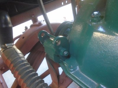
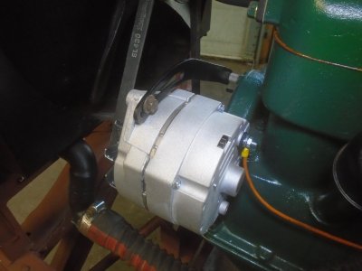
I'm using one of the newer GM one wire alternators and it will not bolt up to the generator mount on the model-A engine.
So I made up this bracket that bolts onto the model-A mount and the alternator can then bolt onto it.
The bracket fits up against the side of the engine so it is held in place and can't pivot.

DSC07399.JPG


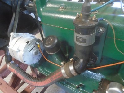
The alternator fits nicely onto the bracket. The coil is changed over to a 12-volt coil that uses an external ballast resister.
I made up a flat steel plate that bolts onto the side of the engine behind the water inlet fitting and the coil bolts to that.

DSC07400.JPG


Sorting thru my collection of generator and alternator tension brackets, I found one that was just the right size and didn't need any modifying ( that doesn't happen very often ).

DSC07401.JPG


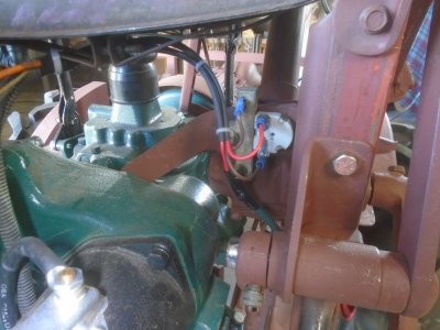
The ballast resister is bolted the steering column mount under the left side of the gas tank. The green wire coming up along the angle iron support is the wire from the solenoid that give the coil the full 12-volts while starting.
The other ( round ) unit beside it is the voltage reducer to cut the 12-volt power down to 6-volts for the old headlights.

DSC07401-1.JPG


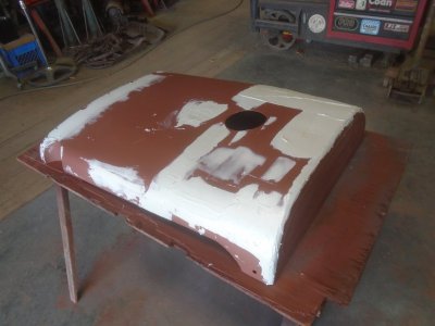
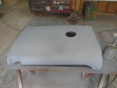
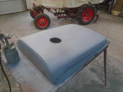
The weather has been decent enough to start putting body fill on the sheet metal parts.

DSC07402.JPG

DSC07403.JPG
 
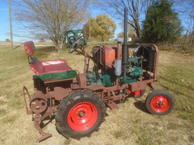
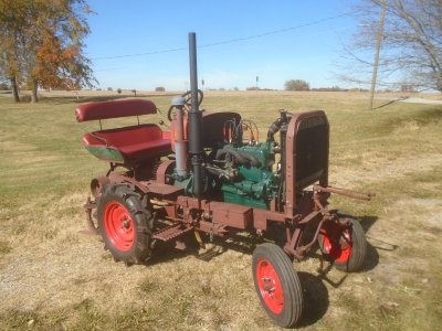
Drove the tractor out of the garage today. The engine is running all of these photos. It runs good and doesn't smoke.

DSC07405.JPG

DSC07406.JPG


It runs for a little while and then it stalls out for lack of fuel.
I've got good gas flow to the carb so I'm thinking the float or the needle valve is sticking.

DSC07407.JPG


Alternator works fine.

DSC07408.JPG
 
When I had first turned the gas valve on the other day to start the tractor for the first time, there was a good stream flowing into the fuel bowel.
I pulled the carburetor off today and when I loosened the gas line going into the carburetor, there was gas in the line.
Took the carb apart and it looks good and clean. The float is set right and the needle isn't sticking. I still went ahead and took it all apart and made sure that all the little fuel passageways were open and clean.

Put the carb back on and started it up. After a couple of minuets of fast running it stalled out. I imediantly closed the gas valve on the fuel bowl and when I loosened the line fitting on the carb it was dry.
So I took off the glass fuel bowl and opened the valve and this is all the flow that is coming thru with the valve wide open.

DSC07411.JPG


I took the fuel bowl off and found that there is sediment building up in the line coming out of the tank. I flushed the tank out and pressurized it to blow the line clear.
Put everything back together and had the engine running at a fast RPM for over an hour.
 
Back
Top