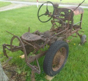
Ford model-T tractor converson

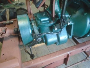
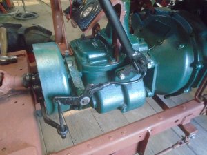
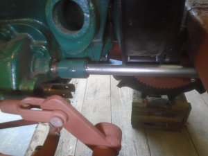
Finished making the linkage rod for the parking brake.
This is with the brake released.

DSC07077-1.JPG


And the brake engaged.

DSC07077-2.JPG


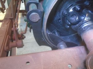
Normally on drum style parking brakes, there is a brake band that goes around the outside of the drum.
This one has two brake shoes. One on the the outside of the drum and one on the inside of the drum.
They grip the drum between them just like a vice grip and it really holds the drum firmly.

DSC07077-3.JPG


Now to move onto something that I have been waiting to work on for a very long time.
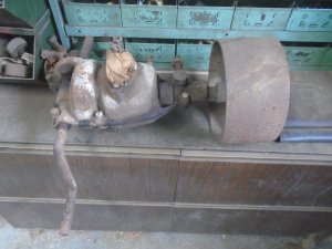
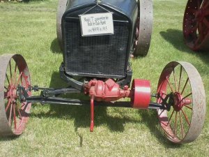
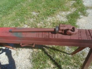
This is a flat belt drive system to put on a model-T for powering equipment around the farm that was driven by belt power from a tractor.
I got this one out of a second hand shop over 40 years ago.

4.JPG


It is designed to mount on the front of the model-T and is powered off the front of the engine.
It has an extension for the hand crank built into it for starting the engine.

5.jpg


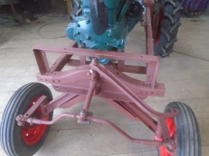
Obviously, this can't mount on the front of my tractor because the front axle mount and the steering arm are directly in front of the engines crankshaft.

DSC06663.JPG


This is why I went to all the trouble of adapting that Chevy truck transmission to the engine. The transmission has a power takeoff on it so I can mount this on the back of the tractor and drive it with the PTO from the transmission.

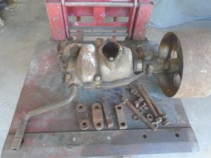
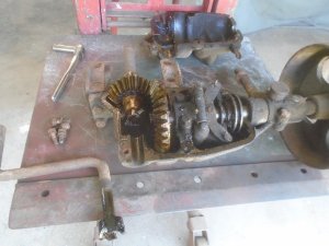
First thing is to start taking it apart so I can clean it up.

DSC07078.JPG


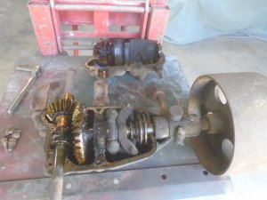
I'm very pleased to see that the gears and bushings look really good.

DSC07079.JPG


With this being mounted on the back, I won't need the hand crank so that is removed and the hole will be plugged later on.

DSC07080.JPG


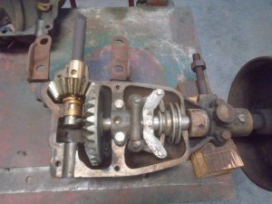
The inside cleaned up good.

DSC07082.JPG
 
Amazingly good inside for probably a 100 yr old unit, I'm curious about the spring lever assy toward the pulley it looks like it could be a clutch assy?

That is a governor to control the speed of the engine. The grooved pulley to the right will move in along the shaft as the governor weights are thrown out from cintrifical force. There is a lever that rides inside the pulley groove to connect up to the throttle on the carburetor.
 
That is a governor to control the speed of the engine. The grooved pulley to the right will move in along the shaft as the governor weights are thrown out from cintrifical force. There is a lever that rides inside the pulley groove to connect up to the throttle on the carburetor.
Ok so are you going to install the gov function, or does it have a gov on the engine now
 
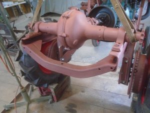
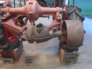
The flat belt pulley assembly is designed to mount onto the drop center part of the front cross frame of the model-T.
It just so happens that I have one of those frame sections up on the storage racks. It is now welded onto the end of the rear frame rails.

DSC07086.JPG


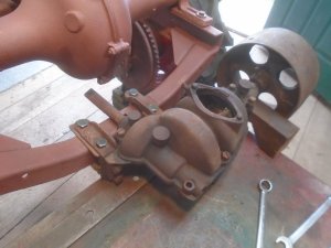
Starting to fit the pulley drive housing mounts to the frame.

DSC07088.JPG


It is now bolted onto the frame.

DSC07092.JPG


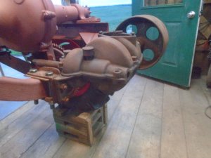
The pulley is set so it hangs outside of the side frame rail.

DSC07093.JPG


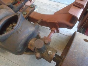
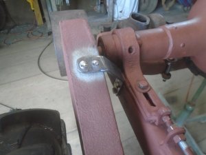
There is a 5/8 threaded hole in the casting close to the pulley that has a stud threaded into it. I made up a bracket with a hole in it for the stud to fit thru and it is welded to the frame.

DSC07095.JPG


There is a nut on either side of this bracket so they can be tightened up to support the pulley housing.

DSC07096.JPG


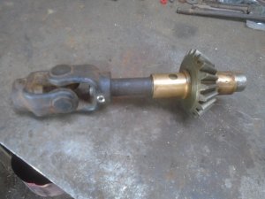
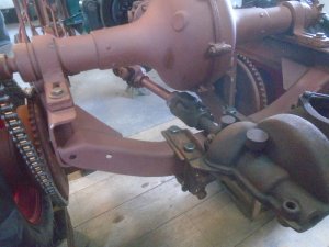
A universal joint is mounted on the drive shaft.

DSC07097.JPG


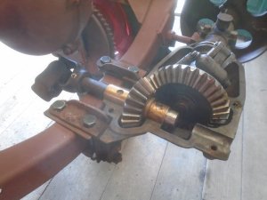
And the shaft is set back into the housing.

DSC07098.JPG
 
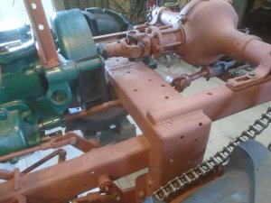
Making up the drive shaft to go from the PTO on the side of the transmission back to the flat belt pulley drive unit.
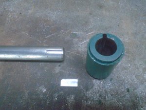
The keyway is machined into the steel shaft and the collar that will fit onto it.

DSC07099.JPG


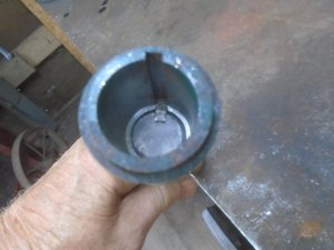
This hole in the other half of the collar fits onto the shaft on the PTO.

DSC07100.JPG


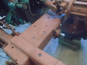
The collar is slid onto the PTO shaft and the drive shaft extends back under the rear frame crossmember.


There is a shaft coming out of the PTO along side the drive shaft. This engages and dis-engages the PTO by moving it in or out. There will be a hand lever to operate that but I'm not going to make that until after the seat is mounted.

The seat will be here in two weeks.

DSC07101.JPG


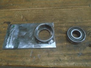
Making up a mounting bracket to hold a bearing.

DSC07102.JPG


This bracket bolts onto the back side of the crossmember to support the end of the drive shaft.

DSC07103.JPG


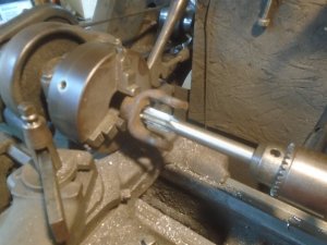
Machining out the universal joint.

DSC07104.JPG


The universal joint and the bearing are mounted onto the end of the driveshaft.

DSC07105.JPG


This is mounted back onto the tractor and a shorter drive shaft is made up to go on back to the pulley drive unit.

DSC07106.JPG

DSC07107.JPG
 
Last edited:
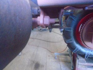
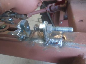
I made up adjusting brackets for positioning the rear axle. There is a block of steel welded to the end of the axle mounting bracket. This steel block has a counterbore drilled into it that the cone shaped head of the adjusting bolt fits into.

DSC07111.JPG


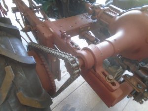
With the chains on, the adjusting bolts are screwed out to push the axle back and take the slack out of the chains.

DSC07112.JPG


Getting an idea of where the chain guards will sit.

DSC07113.JPG

DSC07114.JPG


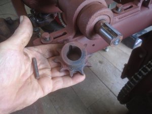
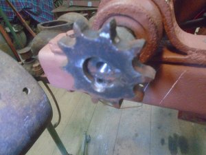
You may remember that the spread of the sprockets on the axle was a little narrower than the sprockets on the hubs. The sprockets are held onto the axle shafts with a solid dowel pin. I have removed the sprockets and the solid pins.

DSC07116.JPG


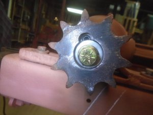
The hole the pin was in is tapped with a 5/16-18 thread. The axle sprocket is moved out to line up with the hub sprocket . A 1 inch long set screw is threaded into the hole until the end of the set screw is flush with the end of the axle shaft.

DSC07117.JPG


The center of the axle shaft has been tapped for a 3/8 bolt that holds a washer that covers over the end of part of the set screw so it can't accidentally come out.

DSC07118.JPG


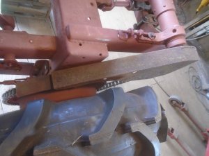
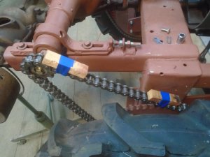
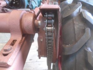
The chain is put back on and wood blocks are taped to it for the chain guard to sit on.

DSC07119.JPG


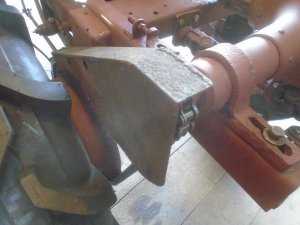
The first mounting bracket is bolted to the side of the frame and welded to the chain guard.

DSC07120.JPG
 
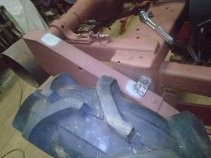
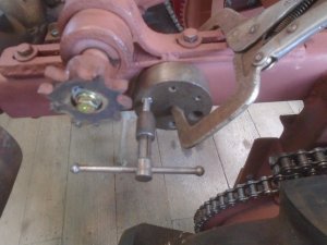
A tapping guide block is clamped to the side of the frame to make sure that the mounting holes are threaded in straight.

DSC07124.JPG


The rear mounting bracket is bolted onto the frame and welded to the chain guard.

DSC07125.JPG


This shows the clearance on the inside.

DSC07126.JPG
 
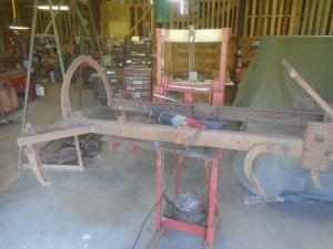
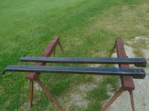
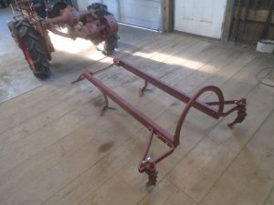
Ready to start on the cultivator frame. This was built using the frame rails from a Ford model-T. The tractor would straddle the crop to till the ground on either side of it so there is a curved piece of steel on the back to clear the crop as the tractor is driven down the row. There is an outrigger frame on each side with a cultivator mounted on it to till the ground after the rear tires roll over it.

This whole frame was raised and lowered by the long handle mounted on the right side of the tractor frame. I have been impressed with the engineering and the quality of the construction by the original owner but the cultivator lift system on this did not impress me. It was designed so the lever had to be pushed forward to lift the frame up.

It is very hard to lift the weight by pushing the lever forward. It works much better if you can pull back on the lever to lift the weight so you can brace yourself with your feet. The lift system will be completely re-designed.

12 (2).JPG


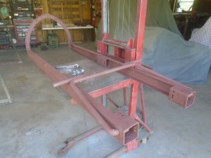
I'm using my die cart to lift the cultivator frame up to make it easier to start taking it apart. There are four cultivators mounted on the front of the frame and the two mounted behind the rear wheels.

DSC07129.JPG


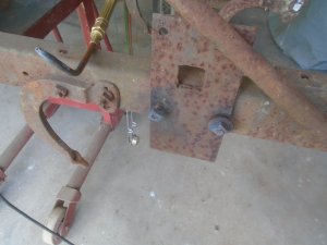
Everything is rusted solid so the nuts have to be heated up so they can be removed.

DSC07130.JPG


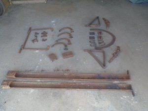
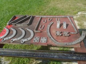
Here are all the pieces.

DSC07132.JPG


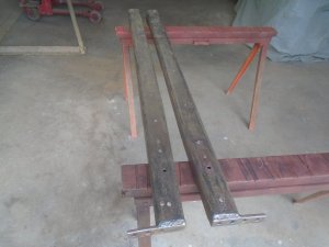
The two frame rails are cleaned up with an air powered grinding discs and a wire brush attachment.

DSC07133.JPG


I put them outside and sprayed them down with a liquid rust treatment. This leaves a dark finish on the metal after it has dried.

DSC07134.JPG


The other parts were small enough to fit into the sand blast cabinet.

DSC07135.JPG


After the parts are primed, I started putting them back together.

DSC07136.JPG


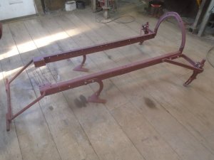
Here is the finished frame ( minus the two inside front cultivators ).

DSC07137.JPG


It is ready to have the tractor rolled back over it so I can start to figure out how to build the lift system.

DSC07137-1.JPG
 
When I added the flat belt pulley assembly to the back of the tractor, I knew that I would have to lengthen the cultivator frame so that the arch support on the back of it would clear the pulley housing. Before I could do that, I had to assemble the cultivator frame as is and set it under the tractor in order to be able to tell how much it needed to be lengthened.

I have the cultivator frame sitting so the arch support will clear the pulley housing. In this position, the rear cultivators are positioned far back from the rear wheels and would not fallow in the tire track on a tight turn.
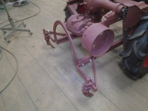
DSC07139.JPG


The front mount for the cultivator frame needs to come forward to about where the blue tape is on the side of the tractor frame. This would move the rear cultivators forward to their original position in relation to the rear tires.
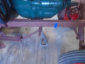
DSC07140.JPG


The cultivator frame is clamped down to the platform of the die cart and the rear cultivators and the arch support are removed. The mounting tabs for the arch support will be cut off the frame rails.
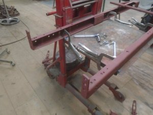
DSC07141.JPG


Luckily, whoever built this tractor used several pieces from another model-T frame for the supports in this frame.
This is a photo of the original tractor frame. I used the two cross pieces on the right to extend the tractor frame back and mount the rear axle on them.
I'm going to use part of the other two pieces that are sitting at an angle and holding the original transmission in place.
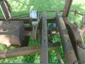
DSC07141-1.JPG


Here are those two frame pieces. They are both tapered about 1/2 inch from end to end so I will be cutting a section off each of them so they match.
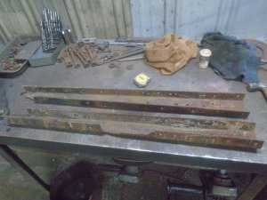
DSC07142.JPG


The frame needs to be extended out 7 inches. I cut the the extensions pieces at 11 inches so there is 3 inches of the frame extension that fits inside the end of original frame rails.
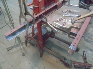
DSC07143.JPG


With the frame extensions welded in place, I bolted the rear cultivators back on and used a piece of angle to clamp across them to hold them in line. Then I welded the mounting brackets for the arch support to the ends of the frame rails.
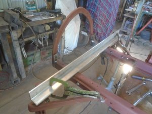
DSC07145.JPG


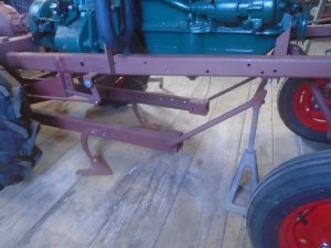
Now the front of the cultivator frame is sitting forward where it belongs.
DSC07149.JPG


This puts the rear cultivators closer to the tires and still leaves about 1-1/2 inch clearance between the arch support and the pulley housing.
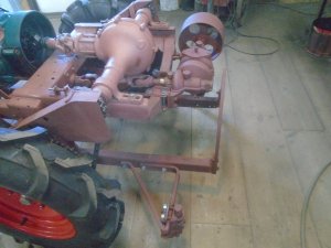
DSC07150.JPG


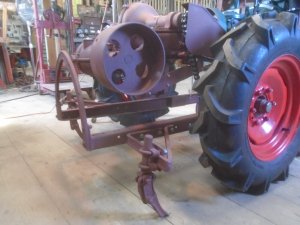
There is plenty of room to raise the cultivators off the ground and still have good clearance around the flat belt pulley.
I figure that when I'm using the flat belt pulley, I would most likely drop the cultivators down to the ground so that clearance would not be an issue anyway. Still, it's good to have it so the rear cultivator doesn't hit against the pulley while the tractor is being driven around.
DSC07151.JPG
 
Back
Top