Free tractor

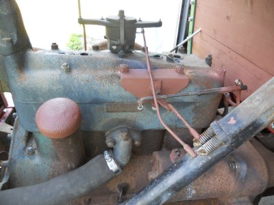
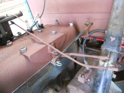
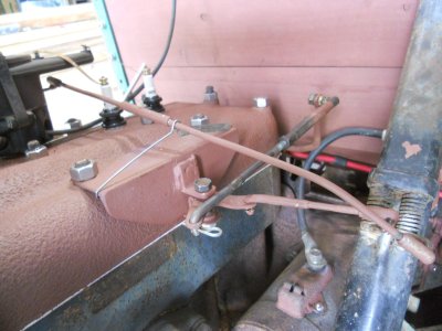
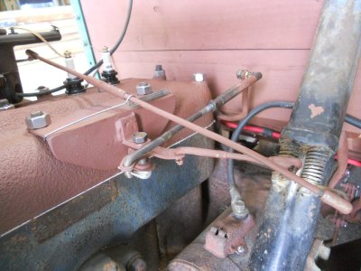
Both the throttle and spark advance rods are made up and installed.

DSCN3504.JPG


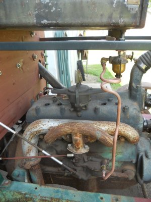
Today I put on the fuel filter bowl with a shutoff valve and made up the fuel line going down to the carburetor.
I decided that since the fuel filter is right over the engine, I didn't want to use a filter with a glass bowl so I found one with a brass bowl.

DSCN3506.JPG

I have the spark plugs out and cranking it over to get #1 on TDC so I can set the distributor.
# 2 and 4 have good compression but #1 and 3 have no compression so obviously, a couple of valves must be stuck open.

Time to pull the head.
I probably should have done this when I first got the tractor but the engine turned over so easily that I was thinking ( or hoping ) everything was okay inside.
 
The cylinder head is back on the engine and #1 piston is a TDC so I can set the timing.
The model-A, 4-cylinder engine has this pin threaded into the front of the timing cover.

To find TDC on #1 with the cylinder head on, this pin was un-screwed and turned around and stuck back into the hole.
There is a small indented spot on the front of the timing gear and the engine crank was rotated until you felt the tip of this pin slip into the indented spot.

Before I put the head on, I used this pin and I was not able to feel the indented spot with the pin.

DSCN3619.JPG


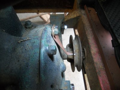
With the head on, I'm not going to be able to find TDC again later if I need to.
So I ground a notch on the back flange of the crank pulley and made up a marker point out of stainless to mark TDC.

DSCN3620.JPG


The distributor is mounted solid in the head.
The center shaft in the distributor has a collar on it with a notch in it.
They make this special tool for rotating and holding this collar.

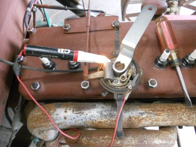
To set the timing, you hook a test light between the wire on the points and engine ground.
The collar is rotated clockwise until the test light just comes on.
That means the points have just closed.
Then, holding the collar firmly in place, you tighten the center screw to lock the collar in place.

DSCN3604.JPG


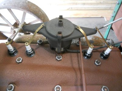
The rotor is pushed down onto the collar and the distributor cap is put on.
Hook up the four brass strips between the distributor cap and the spark plugs and the distributor is finished.

DSCN3608.JPG


The spark advance rod is bent on the end to fit down onto the lever on the steering column.
There is nothing to keep it from laying over and rubbing against the edge of the throttle bracket on the head.

DSCN3613.JPG

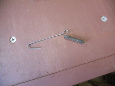
I made up a retaining clip out of stainless wire and a small spring.

DSCN3614.JPG


One end of the wire fits under the front edge of the throttle bracket and the other end fits down over the spark advance rod.
One end of the spring fits onto the wire, then goes under the rod and fastened to the back edge of the throttle bracket.
This holds the spark advance rod up off the engine.

DSCN3611.JPG


The lever on the steering column pulls the rod down some when the spark is advanced but the rod is still held up off the engine.

DSCN3612.JPG


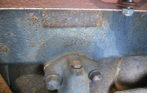
The 1928 - 1931 Ford model-A cars, pickups and 1-1/2 ton trucks all have the serial number stamped on the side of the engine above the water inlet fitting.
This engine does not have a number stamped on it and that has always baffled me.

DSCN3621.JPG


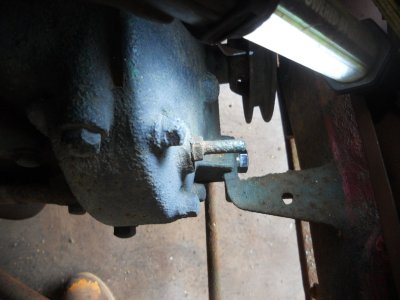
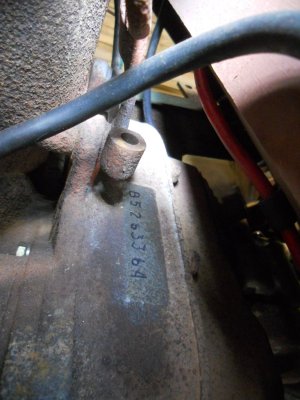
After doing some searching on the internet, I found that, starting in 1932 with the model-B, 4-cylinder engines, the cars and pickups still have the numbers stamped on the side of the block but the 1-1/2 ton trucks have an area on top of the bellhousing where the numbers are stamped on it.

I had to use my small air powered belt sander to clean the rust off to find the numbers.
Then I went over them with a felt tip marker and sprayed clear over the area.

This serial number was issued in early December of 1933.

DSCN3622.JPG
 
The cylinder head is back on the engine and #1 piston is a TDC so I can set the timing.
The model-A, 4-cylinder engine has this pin threaded into the front of the timing cover.

To find TDC on #1 with the cylinder head on, this pin was un-screwed and turned around and stuck back into the hole.
There is a small indented spot on the front of the timing gear and the engine crank was rotated until you felt the tip of this pin slip into the indented spot.

Before I put the head on, I used this pin and I was not able to feel the indented spot with the pin.

View attachment 95525


With the head on, I'm not going to be able to find TDC again later if I need to.
So I ground a notch on the back flange of the crank pulley and made up a marker point out of stainless to mark TDC.

View attachment 95526


The distributor is mounted solid in the head.
The center shaft in the distributor has a collar on it with a notch in it.
They make this special tool for rotating and holding this collar.

To set the timing, you hook a test light between the wire on the points and engine ground.
The collar is rotated clockwise until the test light just comes on.
That means the points have just closed.
Then, holding the collar firmly in place, you tighten the center screw to lock the collar in place.

View attachment 95527


The rotor is pushed down onto the collar and the distributor cap is put on.
Hook up the four brass strips between the distributor cap and the spark plugs and the distributor is finished.

View attachment 95528


The spark advance rod is bent on the end to fit down onto the lever on the steering column.
There is nothing to keep it from laying over and rubbing against the edge of the throttle bracket on the head.

View attachment 95529

I made up a retaining clip out of stainless wire and a small spring.

View attachment 95530


One end of the wire fits under the front edge of the throttle bracket and the other end fits down over the spark advance rod.
One end of the spring fits onto the wire, then goes under the rod and fastened to the back edge of the throttle bracket.
This holds the spark advance rod up off the engine.

View attachment 95531


The lever on the steering column pulls the rod down some when the spark is advanced but the rod is still held up off the engine.

View attachment 95532


The 1928 - 1931 Ford model-A cars, pickups and 1-1/2 ton trucks all have the serial number stamped on the side of the engine above the water inlet fitting.
This engine does not have a number stamped on it and that has always baffled me.

View attachment 95533


After doing some searching on the internet, I found that, starting in 1932 with the model-B, 4-cylinder engines, the cars and pickups still have the numbers stamped on the side of the block but the 1-1/2 ton trucks have an area on top of the bellhousing where the numbers are stamped on it.

I had to use my small air powered belt sander to clean the rust off to find the numbers.
Then I went over them with a felt tip marker and sprayed clear over the area.

This serial number was issued in early December of 1933.

View attachment 95534
Hi JD so is this engine a Model B engine? I like what you did with the advance rod and the TDC pointer
 
Yes, it is a model-B

Modified Ford Model Bs


It was known as the Model B engine and was produced for only four years beginning in 1932. Sporting only four cylinders, it was basically an upgrade of the earlier Model A powerplant. The “B” engine sported an impressive 200 cubic inches of displacement. Its compression ratio was a super-low 4.9-1. The paltry 50 horses it produced came at about 2,200 RPMs. The engine certainly didn’t appear likely to be a candidate for upgrading, but that wouldn’t be the case.

Shortly after its introduction, there was a wave of professional upgrades that evolved making every stock Deuce a potential race engine.

And, single-car garage engine builders would find many different ways of devising methods to triple, and sometimes more, it horsepower with a multitude of aftermarket and homemade performance parts.

It was a favorite of two types of motorsports fans.

First, there was the type that looked at it for performance street. But the performance improvements that were possible also made it an excellent candidate for oval track racing with the sprint car (then called big cars). There was one common component in a majority of the conversions, that being a pair of two-barrel carbs, usually Winfields.

All these conversions could run on either alcohol or high-test (then called ethyl) fuels, but for alcohol, it was necessary to open up the jets for more flow. The compression ratios were also higher for alcohol use.

Established B Block Aftermarket Conversions:

HAL B Block Conversion

The HAL conversion was a popular racing conversion for the Deuce. This conversion lasted into the 1950s where it was still competitive. On some occasions, the block was bored out to about 220 cid.
Besides the HAL cylinder head, there was also a balanced crank, and either a single or double overhead cam. The latter was the preferred system if the pocketbook would allow it.

It also used a pair of single-barrel carburetors. It’s compression ratio was about 7-1. It was reported that some of these set-ups were capable of producing one horsepower per cubic inch of displacement, which was a pretty heady accomplishment for the time period.

In addition, the very early HAL engines had carburetors sitting on top of the engine instead of the normal side-draft position. Hal B Block conversions have been noted with different displacements, some bored out to 220 cubic inches and sporting a balanced crank.

One restored 1934 HAL sprinter had an illustrious history and carried Flynn carburetors along with magneto ignition.

It burned alcohol. During its racing days, it won the NARA Northeast series and was reportedly driven by Indy 500 driver, Bill Holland.

Dreyer B Block Conversion

Pop Dreyer was one of the best-known engine builders of the period. His cast iron heads connected to the B Block provided one of the best sprint car powerplants during the 1930s. The engine also sported twin Winfield carbs, aluminum intake manifold and a SOHC cam set-up. It was reported that these engines could produce over 200 horsepower.

He later would build a block of his own which would incorporate a double overhead cam and five main bearings instead of the three on the standard B Block.

RAMAR B Block Conversion

The RAMAR conversion consisted mainly of the RAMAR high-compression cast iron head. The set-up was a perfect match for the early B Blocks. The cast iron head was connected to a pair of one and one-quarter inch Winfield Carbs. Also included in the package was a dry sump oiling system and magneto ignition. The horsepower was reported at about 150.

Miller-Schofield B Block Conversion

This conversion was a joint effort with racecar builder Harry Miller. The effort was financed by a group headed by George Schofield. The main component that evolved was the so-called Miller High-Speed Head, which was carried on the valve cover.

Again, the Winfield carb would be a player with this conversion. One of the big players in this operation was Leo Goosen who made the head design drawings.

Crager B-Block Conversion

This conversion could really be included as a part of the previous paragraph, but for clarity purposes, it is presented separately. This conversion was born following the failure of Miller-Schofield to continue in business. Cragar decided to scoop off the pieces and modified the Hi-Speed Head to its liking and carrying the new name.

A Cragar conversion was seen with a bored 213 B Block with the Cragar head, a pair of Winfield carbs, a drilled crank, and a pressure oil system.

Riley Four-Port Model B Conversions

This interesting conversion was somewhat different from the others of the period. It featured, for example, a Riley four-port OHV head, a pair of Stromberg 97 carbs and Mallory Ignition. The configuration featured intakes inside the head with exhausts in the block. It should be noted that replicas of the Riley head are currently being fabricated by the Scalded Dog Speed Parts in Batavia, Ohio (513-724-0700
icon12.png
) to precise detail of the original.

(Note) The author would like to thank Charlie Yapp for his assistance in this article.

 
Back
Top