John Deere Quik-Tatch hitch on Massey Ferguson 1655

May be I already explained this previously but anyway, lately I found out that my hitch is not letting the snowblower sitting properly on the ground. The scraper blade is touching at the back instead of the front. This leaves a lot of snow on the ground and sometimes it causes the blower to "climb" on snowbanks instead of ripping through it.

I was looking for a while now the height of the main pivot pin from the ground. Seems I did not evaluate this properly and this causes my problems. A member of MTF was nice enough to provide me the measurement measured on his 445 resting on concrete with the blade down on float.
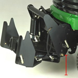
bm19782.jpg

Since there are multiple versions of this hitch, there can be variations to this height. Here is what I know so far, measure taken from the ground to the center of the pin.

BM17347 : 425, 445, 455 : 7.5" -- This is the hitch I used. I had the height at 6.25" and it makes quite a difference!
BM18120 : F900 series
BM18121 : 318, 322, 332 : 8.5"
BM18122 : 420, 430 : 6.5" (at least for the 430 which has an extension frame. 420 not sure.)
BM19782 : x465-x595, X700 series : 7.75"
BM20921 : 2210
LVB24898 : 4010, 4100, 4110, 4115

I will probably modify my hitch this weekend to fix this mistake. Should be relatively easy, drill higher, cut the hitch under this new hole and make a new bracket for the top of the hydraulic cylinder.
 
I finally did raise the main pivot point recently, from the 6.25" I had to 7.5"! It solved the angle of the snowblower. The blade on the other hand has a higher tendency to "dig" in my driveway's imperfections but this might be due to the current wear of the usage with the previous height (which changed the angle of the blade). It still seems to rip ice from the asphalt as it did before.

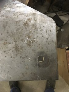
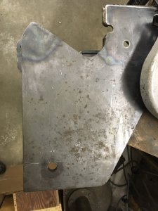
Here is the layout for my cut, it happened to be quite exactly on top of the previous hole. I like it this way, the mistake "disappears" (;
IMG_8237.jpgIMG_8238.jpg

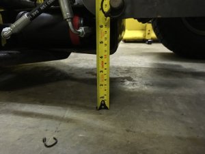
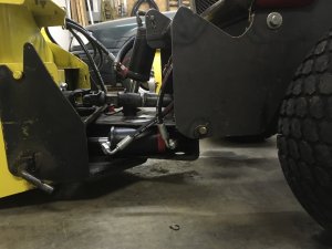
And here is the height measurements and final look. I took the time to round the lower front portion of the hitch so it's less agressive if it touches down. At least now it's 3.25" higher than previously, the hitch was hitting the ground too easily.
IMG_8246.jpgIMG_8247.jpg

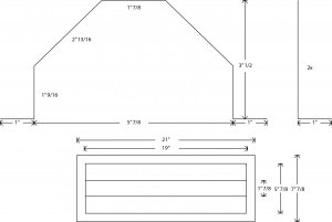
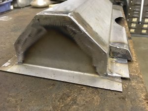
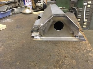
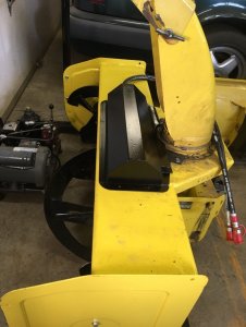
Also, my friend who welded the PTO shaft should be able to bend the parts I need to make the chute rotation cylinder cover. This is much needed to avoid it getting jammed with snow/ice. Here are the plans for the parts, I will do the welding myself once I will have figured out the final dimensions. It will be made in 1/16" thick steel which I will paint black.
cover.jpg
 
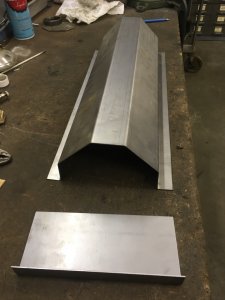
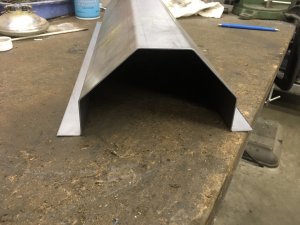
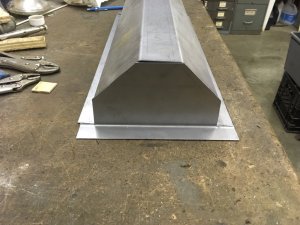
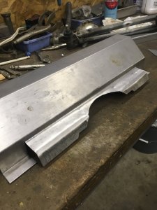
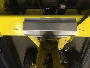
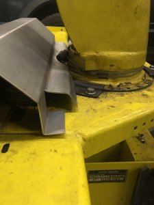
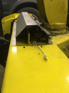
I got my "sheet metal" parts for the cover and started to fit it.

IMG_8293.jpgIMG_8295.jpgIMG_8297.jpg

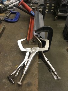
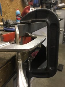
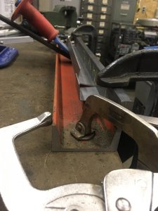
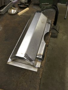
I had to be creative a lot to make a bend that was not on the full width, this is to let the cables go around the chute. It was not easy but I managed to make a reasonably clean bend. To make the bend I was holding the part under my workbench with one hand and I was pulling the chisel "upward". I made many iterations until I was unable to bend more at which point I clamped another flatbar behind the section to bend, applied force with a pipe wrench and hit the flatbar with a hammer in the direction of the bend to get the metal to "remember" the bend.
IMG_8298.jpgIMG_8299.jpgIMG_8300.jpg

I made some more cuts in the part, it's not finished but here is where I am now. There will be some covers welded for the small gap you can see bottom left between the two opposed bends.
IMG_8302.jpg

Here is what it looks on the blower so far
IMG_8303.jpgIMG_8304.jpgIMG_8305.jpg

To be continued...
 
Finally I have time to make an update of the progress.

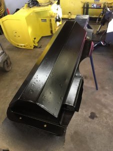
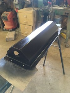
First I finished the cover, I welded both ends and I made a hole for the hoses to the cylinder. BTW I was too lazy to switch my welder to MIG therefore the welds were made with flux cored wire, not the best result around but I don't care
IMG_8351.jpgIMG_8352.jpgIMG_8353.jpg

Then I painted it black... Had a lot of trouble getting the paint to stick, seems I didn't clean it properly before painting. In the end there are 2 coats of POR15 then a sprayed on primer then 2 coats of metal spray paint... The dips are where the POR15 was not sticking.

IMG_8480.jpgIMG_8481.jpgIMG_8482.jpg

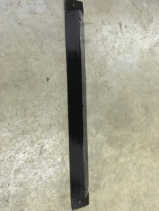
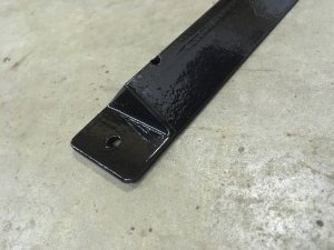
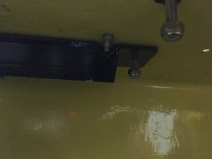
And I also made the last part I needed, the "cover" that goes inside the housing to protect the bolts for the pulley stacks. It's only an angle with caps at the ends that are used to bolt it in place. On this one I didn't have troubles getting the POR15 to stick (:

IMG_8525.jpgIMG_8526.jpgIMG_8527.jpg

The project is now mostly complete! The winter is also over but at least it worked properly this winter and it will be ready for the next one. I hope to find an old crazy carpet to cut a washer to put between the housing and the chute. Also eventually I'll see to have the spout controlled by a hydraulic cylinder but I have other projects to work on for now so it will probably wait.
 
Somehow, I missed this. What a write-up.
Thanks for the time and effort. Also, letting us see it.

Nice job
 
I made some "indirect" progress lately to this project. Some of you might have seen that I bent the frame of my 1655 most probably while ripping ice off my drive way. Details here Limits of a Massey Ferguson 1655/1855

Well I finally made a subframe to hopefully eliminate this weakness. The main goal is to redirect the kinetic energy of the counterweight directly to the QuikTatch hitch when the tractor hits something hard like thick ice. Secondary goal being to try to reinforce the tractor's frame where it is changing width close to the engine but this is really secondary and probably not fully resolved in the current state.

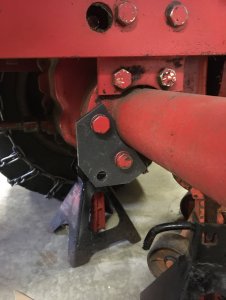
First here is where I attach the subframe at the back of the tractor. I made some 1/4" plate that bolt to the axle a bit like the frame does. Close to this at the back of the axle is where the lower 3pt hitch is attached to. I didn't take pictures of the finised plates but where the hole is for the subframe I added 1/4" thick plates on both sides to make the width a total of 3/4". This will minimize the wear that the pin might want to inflict on the hole during shocks.
IMG_9248.jpg

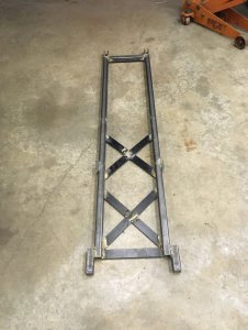
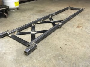
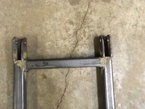
Here is the current subframe. It's made of 1.25 x 1.25 x 1/8" square tube and 1.5 x 1/4 flat bar. All the holes (6 of them) through the frame are reinforced with tubes welded inside the tubes Given the tubes are only 1/8" thick, without this the holes would have too much tendency to deform.

The bottom of the first picture is the front of the tractor. You might guess that my mounts at the axle are conveniently placed 1.25" off of the front of the tractor's frame width up front.
IMG_9251.jpgIMG_9252.jpg

Those are the rear mounting points to the tractor's axle, I made some "U" out of 1/4" plates.
IMG_9255.jpg

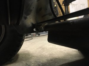
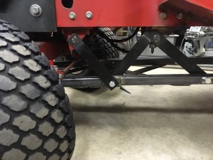
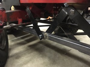
Here are some incredibly bad pictures to try not to show you how it's attached up front on my custom QuikTatch :confused: In short, the subframe attached right behind the main pivot of the QT. There is a hole in the QT and I added L bent flatbars to increase the surface area for the pins and reinforced those L by adding plate between both sides of the QT.
IMG_9253.jpgIMG_9254.jpg
 
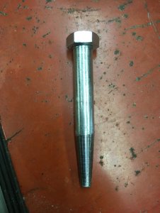
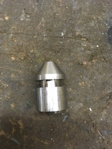
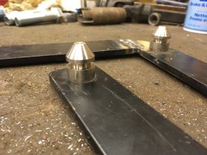
Here are the pins I've been talking about. Being lazy, I bought some 1/2" bolts and tapered the ends on my lathe. 5° angle if someone wonders. The pins are locked in place by "R" clips as I want the frame to be "quick" to install/remove. There are 8 of those pins total.
IMG_9257.jpg

Now going to the braces between the tractor's frame and the subframe. I decided to attach to the exact same mounts as the mower therefore I replicated the pins to use the original lock springs on the mounts.
IMG_9262.jpg

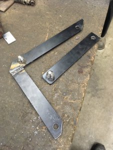
Here is the reinforcing braces for one side
IMG_9273.jpgIMG_9274.jpg

And finally the braces installed. The goal was to make triangles where the tractor's frame is at it's weakest to reinforce it a bit like a bridge or a steel building's roof is made. I think I will find a way to add a horizontal brace at the mower mounting points to "close" the main triangle where I the trame is widening for the engine and where it bent last year. I have to figure out a way to do this without adding too much complexity to the installation/removal process.
IMG_9275.jpgIMG_9277.jpg

I must admit currently the installation and removal are quite hard to do. I made everything so tight that I must use a jack to push the subframe up on the tractor and a prybar to pry it off. All the pins must be inserted by hammer as they align the components. I'll see over the years if this is really a problem or I can live with it. At least it's only twice a year I have to change this.

So far I've hit a small concrete edge between the asphalt and the grass with the blade and the tractor feels rigid as a steel cube would... it's not enjoyable for the operator! Before this subframe I guess the tractor's frame was "springing" and dampening the shock.
 
Back
Top