You are using an out of date browser. It may not display this or other websites correctly.
You should upgrade or use an alternative browser.
You should upgrade or use an alternative browser.
MF 1450
- Thread starter MFDAC
- Start date
I built an adjustable top link this afternoon, Hopefully it will at least be as good as that piece of tubing with pinched ends that was on it when I got it.
It will adjust an inch shorter or longer from this position. The lower arm adjusters are hard to turn. Left one has a bit of a bend in it but still works pretty well. Right one is hard to turn but it's soaking in penetrating oil. I was able to turn it quite a aways, but it's way too hard to do.
DAC
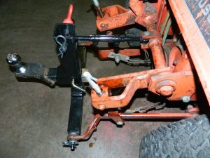
It will adjust an inch shorter or longer from this position. The lower arm adjusters are hard to turn. Left one has a bit of a bend in it but still works pretty well. Right one is hard to turn but it's soaking in penetrating oil. I was able to turn it quite a aways, but it's way too hard to do.
DAC

The 1450 did some work today to earn it's keep and handled what I needed just fine. BUT it isn't charging after all. The last time I wanted to start it it cranked too slow. 7.2 volts in the battery. Going to need to figure that one out now.
Then the 3 point has a mechanical float built into it. I put too much dirt and junk in the back of the utility trailer so not much tongue weight and the trailer pulled the 3 point up when I tried to back up.
My question is, can it be locked when desired? I can't see a provision to do that. I'll try to look closer soon, but tomorrow we have a lot of running around to do, then I go on the "Dreaded on call" at work for a week on Tuesday. May not be very productive during that time.
DAC
Yeah Doug you have to watch for that lol. Its built that way so your ground implements can float.
Is there any way to lock it when downward pressure is needed, Jason? I'm thinking that they just assume there will be enough weight on whatever implement being used. Probably wouldn't have traction anyway if it could be locked.Yeah Doug you have to watch for that lol. Its built that way so your ground implements can float.
Got any ideas on the charging problem? Rectifier, maybe?
DAC
Most garden tractors have some sort of float built into there hitches I think Doug. My Fords have a slot in the lift arm from the cylinder to the sleeve hitch or tiller. You should be able to make a bracket to take the float out. Just my take on it.
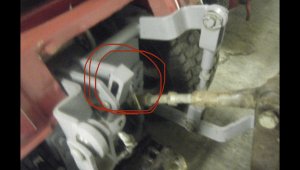
The picture of the 3 point is of a MF 14. I circled the built in float part on those tractors Doug. I don’t know where it is on your tractor.
My John Deere snow thrower has a slot in it where the hydraulic cylinder, for lift and lowering, hooks to it. Even thou the tractor hydraulic lever has a float position.
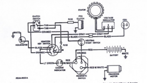
If the rectifier is a three terminal, the middle wire is B. You do a continuity test from the B wire, with it off the rectifier, to the positive post on the battery with the key in the run position. You should have continuity. If not, you have a bad connection somewhere. And it will not charge. Stator check is take the other two wires, which come from the stator, hook up the meter to those two wires and set meter to AC volts. Run engine at full throttle and you should have 28 or more AC volts. If not, there’s trouble with the stator or those two wires. Hope fully I explained that right.
Noel.
Attachments
Last edited:
Thanks for the test procedures, Noel! Will probably have to wait till the weekend. On call again.Most garden tractors have some sort of float built into there hitches I think Doug. My Fords have a slot in the lift arm from the cylinder to the sleeve hitch or tiller. You should be able to make a bracket to take the float out. Just my take on it.
The picture of the 3 point is of a MF 14. I circled the built in float part on those tractors Doug. I don’t know where it is on your tractor.
My John Deere snow thrower has a slot in it where the hydraulic cylinder, for lift and lowering, hooks to it. Even thou the tractor hydraulic lever has a float position.
If the rectifier is a three terminal, the middle wire is B. You do a continuity test from the B wire, with it off the rectifier, to the positive post on the battery with the key in the run position. You should have continuity. If not, you have a bad connection somewhere. And it will not charge. Stator check is take the other two wires, which come from the stator, hook up the meter to those two wires and set meter to AC volts. Run engine at full throttle and you should have 28 or more AC volts. If not, there’s trouble with the stator or those two wires. Hope fully I explained that right.
Noel.
The float happens in the black circled area.
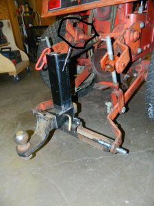
The lift side of that pivot has been repaired at one time. The "L" shaped bracket coming off the cylinder pivots on the shaft for the upper links. It catches the stop on the shaft to lift but is free to let all 4 arms float. No slotted holes.
Thanks again!
DAC
Thanks, Noel! Just got back from an hour at the plant! At least it didn't wake me up in the middle of the night---Yet!Ya, I knew you where on that. Didn’t say any thing. Just be a bad rant and get myself annoyed.
Hopefully things are quiet for you Doug.
Noel
DAC
Like to see a pic of the other side of the circled area. Might have an idea then how to make a temp 'non-float' situation.Thanks for the test procedures, Noel! Will probably have to wait till the weekend. On call again.
The float happens in the black circled area.
View attachment 42723
The lift side of that pivot has been repaired at one time. The "L" shaped bracket coming off the cylinder pivots on the shaft for the upper links. It catches the stop on the shaft to lift but is free to let all 4 arms float. No slotted holes.
Thanks again!
DAC
I will try to get a pic from the other side soon. Probably be Saturday, Kenny. Thanks!Like to see a pic of the other side of the circled area. Might have an idea then how to make a temp 'non-float' situation.
DAC
With most lift systems on garden tractors the key word is lift. many of the components are good for working under suspension or pulling force but much to light to hold up under compression.Hi Doug I was looking at the picture also probably thinking the same as Kenny but it looks to me like it can be done
Don
Hi Doug seems each mfg had their own ideas as how it should work, my PK's have hyd lift with a float position that I only use now & then the Sear Suburbans are all mechanical / arm strong with no real float with the 3 pts on the sleeve hitch's I added a limited amount of floatWith most lift systems on garden tractors the key word is lift. many of the components are good for working under suspension or pulling force but much to light to hold up under compression.
Don
Thanks for the comments everyone! I'll probably be building most of the stuff that gets attached to the 3 point, so if I want some downforce, I'll beef it up accordingly. I am thinking if I ever get to building a new shed, Some dirt work will be needed and some down pressure would be good to rip a little sod. I've got some ripper teeth that I used on the MF8E back when I was tearing up the go-kart track with 25 years ago that may be ok for some downward pressure. Of course, like I mentioned above, light tongue weight in the yard cart is a problem also, and some times, like dumping gravel or dirt out of it, the 3 point will tip up rather than just the dump box.
Here's the pic you asked about, Kenny. That weld looks like I did that repair to the lift lock but it was already there when I got the tractor---LOL!
DAC
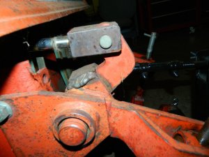
Here's the pic you asked about, Kenny. That weld looks like I did that repair to the lift lock but it was already there when I got the tractor---LOL!
DAC

Looks like some one was trying to stop the float earlier!Thanks for the comments everyone! I'll probably be building most of the stuff that gets attached to the 3 point, so if I want some downforce, I'll beef it up accordingly. I am thinking if I ever get to building a new shed, Some dirt work will be needed and some down pressure would be good to rip a little sod. I've got some ripper teeth that I used on the MF8E back when I was tearing up the go-kart track with 25 years ago that may be ok for some downward pressure. Of course, like I mentioned above, light tongue weight in the yard cart is a problem also, and some times, like dumping gravel or dirt out of it, the 3 point will tip up rather than just the dump box.
Here's the pic you asked about, Kenny. That weld looks like I did that repair to the lift lock but it was already there when I got the tractor---LOL!
DAC
View attachment 42869
That welded on piece is for lifting if that's what you mean, Kenny. I'm guessing the stop broke at some time and a new chunk of plate got welded back on. Hopefully I can get some more pics soon to explain it better.Looks like some one was trying to stop the float earlier!
DAC
Finally not on call at work for about 9 weeks again now! Had to catch up on a few emails, then I got to take a look at the tractor again. It was too hot outside to open the overhead door so didn't try to start it right now so I simulated the 3 point lift with a floor jack.
Lowered all the way down.
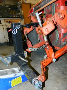
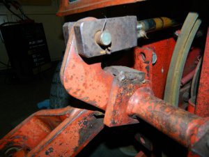
Jacked it up to 10" of lift at the pins.
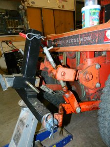
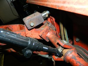
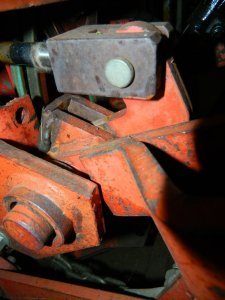
Can't really see a way to lock out the float. I guess will just have to make sure there's more tongue weight on a trailer I may be using. I can just use one of the other tractors for yard cart use when the weight will be on the back of the cart.
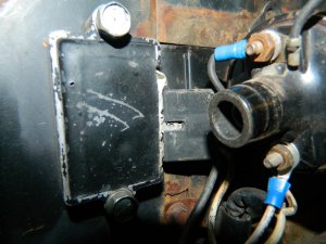
Going to pull the rectifier out and clean the contacts and inspect it better, then do the charging test Noel posted.
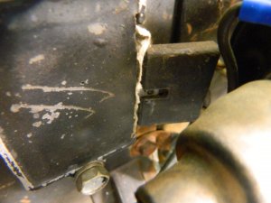
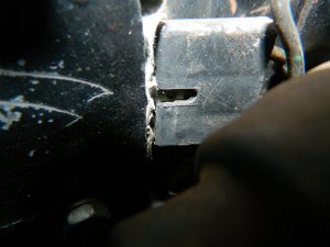
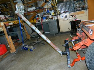
Then I couldn't help myself making a crude mock up of a boom that Jason had talked about in his thread.
Thinking about too much at once. Story of my life. Oh well one of these things will get done soon---LOL!
DAC
Lowered all the way down.


Jacked it up to 10" of lift at the pins.


Can't really see a way to lock out the float. I guess will just have to make sure there's more tongue weight on a trailer I may be using. I can just use one of the other tractors for yard cart use when the weight will be on the back of the cart.
Going to pull the rectifier out and clean the contacts and inspect it better, then do the charging test Noel posted.


Then I couldn't help myself making a crude mock up of a boom that Jason had talked about in his thread.

Thinking about too much at once. Story of my life. Oh well one of these things will get done soon---LOL!
DAC
Looks like a pretty hard place to get a drill into, Jake but will do a little checking into that idea! If that pivot assembly was to ever come out of the tractor for some reason, then it would be much easier! Got no plans to take that apart at this time!You could drill a hole through all three pieces and put a pin or bolt through them Doug. Depending on how much weight is on the back of the cart, you might not need to thick of a pin or bolt.
DAC

