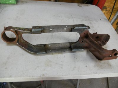
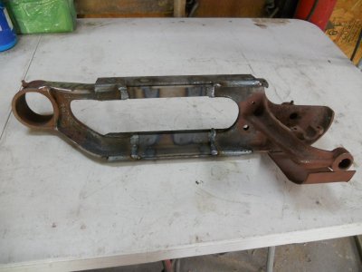
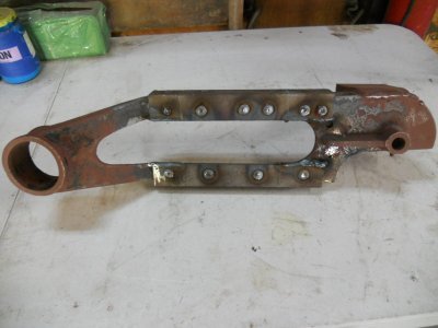
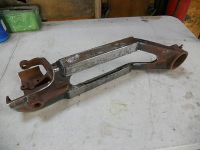
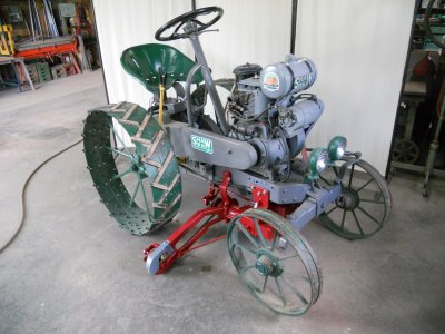
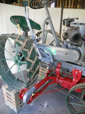
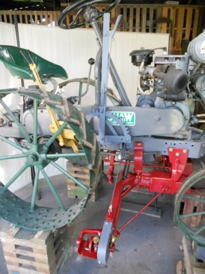
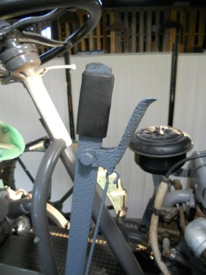
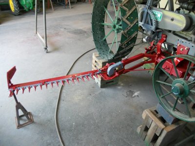
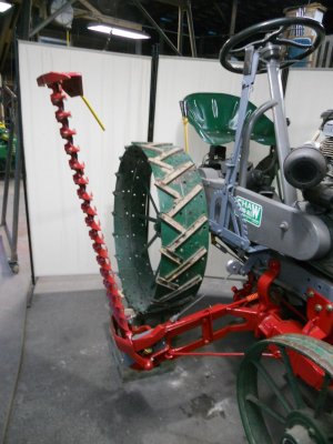
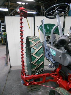
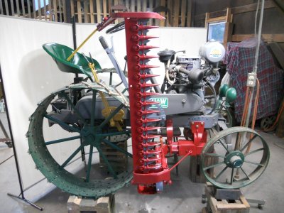
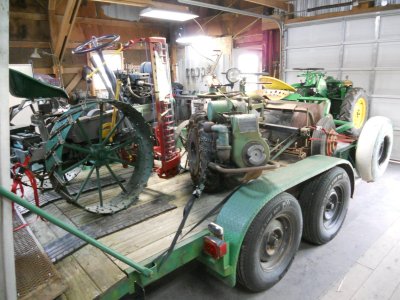
sickle mower

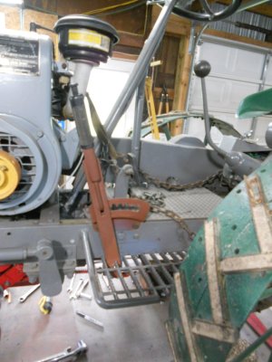
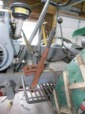
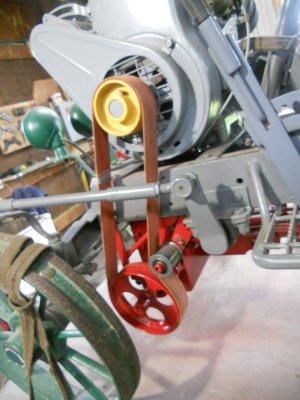
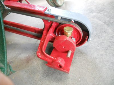
I'm going to make some drastic changes to the design of the flat belt drive system.
Yesterday, someone on another forum asked about the possibility of putting some sort of dog clutch on the drive pulley on the engine so it could be disengaged from the engine when I wanted to stop the belt.
This would keep the belt on the pulley because the pulley would also be stopped from moving.
With doing that, the belt tensioner could be set to hold pressure on the belt all the time.
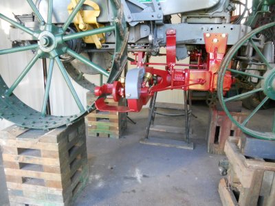
It's and interesting idea but not really feasible in this case because the end of the crankshaft is flush with the end of the pulley. The end of the engines crankshaft would have to be sticking out past the pulley far enough to mount the dog clutch assembly on it.
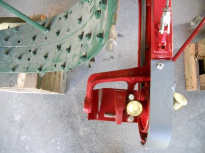

Thinking about this later, I realised that while the dog clutch will not work on the engine pulley, it will work on the shaft under the tractor that goes between the bottom pulley and the right angle gearbox.
I also remembered that I just happen to have the two mating parts for a dog clutch.

DSC04759.JPG


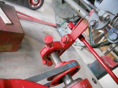
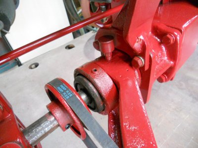
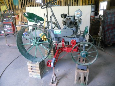
So ... with adding the dog clutch to the lower drive shaft, the belt tensioner will no longer engage and disengage the belt.
It is now be set so the belt is engaged all the time.

DSCN1305.JPG


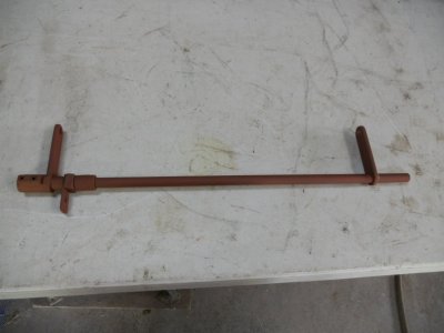
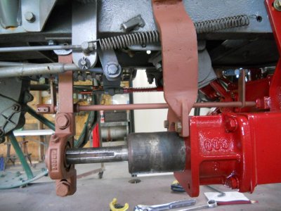
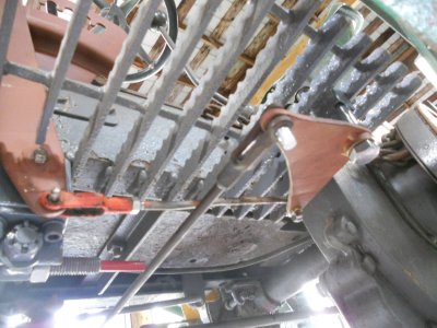
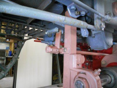
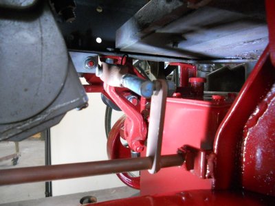
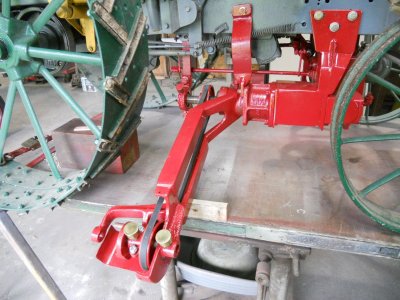
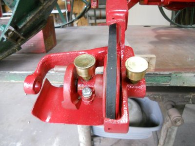
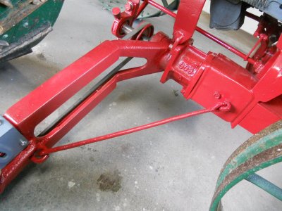
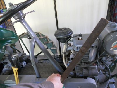
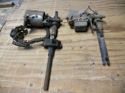
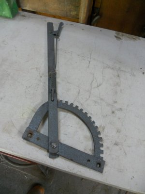
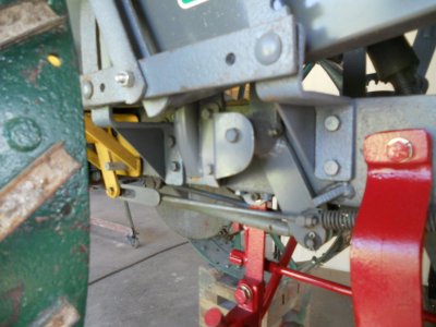
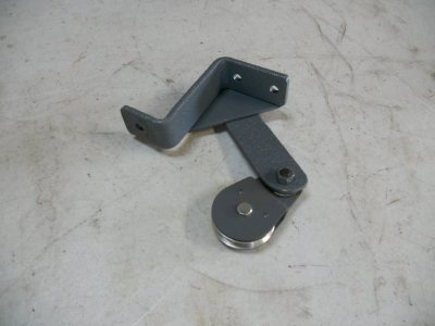
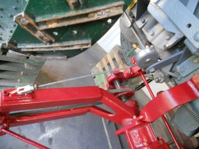
I have a fixed position, spring loaded rod mounted under the tractor that is connected to the tensioner lever arm.

DSCN1306.JPG


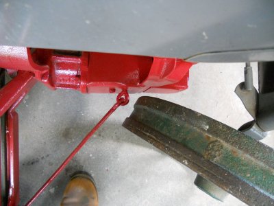
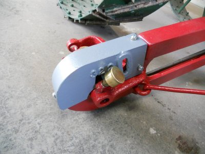
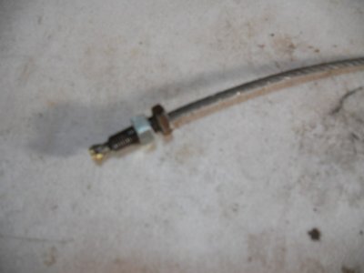
The other end of this rod slips thru a threaded rod. The spring tension is adjusted by turning the nut on the right end of the threaded rod. Once the tension is set, the threaded rod is locked in place with the a locknut of the left side up against the threaded bracket.
After everything was assembled, I saw that there is room to put the locknut on the right side of the threaded bracket so I'm going to switch that locknut.
This will allow more of the threads on the rod to be holding the spring pressure.

DSCN1308.JPG


These are the parts to make the dog clutch work :
The two dog clutch halves.
A splined shaft with a splined collar to fit onto it ( parts off a Ford model-T driveshaft and universal joint ).
A clutch throwout bearing fork to move the one side of the dog clutch in and out ( off a Ford model-A ).

DSCN1309.JPG


One half of the dog clutch will be mounted on the input shaft of the gearbox.

DSCN1310.JPG


The other half of the dog clutch will have the splined collar fit inside it.

DSCN1313.JPG


The splined shaft will be fit onto the drive shaft.
A bearing will be fit inside the dog clutch that will be on the gearbox and the end of the drive shaft will fit into it so that the shaft will spin on the bearing when the dog clutch is disengaged.

DSCN1314.JPG
 
Ray just thinking will that dog clutch bang into gear or can you ease it in. That gear box may not like clanking into gear. Not sure if I'm following all the way.

Not really " bang " into gear but it will start as soon as the teeth make contact so the engine needs to be on slow idle when it is engaged.
The right angle gearbox is off a mower deck and the mower blade was attached to it. The shock of engaging the dog clutch isn't going to be anywhere near as much of a shock as it would get from the fast spinning mower blades hitting obstacles like sticks and stones..
 
Last edited:
Here you can see that the splined shaft has been braised onto the piece of round bar stock.

DSCN1314.JPG


I've machined the excess brass out of the grooves.

DSCN1315.JPG


This allows the collar to slide all the way back now, gaining about 3/4 inch more travel.

DSCN1316.JPG


I'm not going to use the bearing to hold the end of the splined shaft in place as I had first planned on doing.
I've decided that this whole dog clutch assembly is going to be encased inside a metal box that will hold 90W gear lube.
So instead of using the sealed bearing to hold the spline, I will use a bronze bushing. With everything running in oil, it will work much smoother and last longer than it would out in the open.

I'm going to put a hardened 1/2 inch diameter dowel pin in the end of the spline and it will run inside the bushing.
The splined shaft isn't super hard but it is hard enough that it soon takes the sharp edge off a drill so I'm using end mills to bore the hole for the dowel pin.

DSCN1317.JPG


The dowel pin is then pressed into the end of the spline.

DSCN1318.JPG


I pressed a piece of round aluminum inside the dog clutch.
This is being machined out for the bushing to go into it.

DSCN1319.JPG


The bushing is pressed into the hole.

DSCN1319-1.JPG


This half of the clutch fits onto the input shaft of the gearbox.
Once everything is ready for assembly, the shaft will be drilled down thru the holes in the clutch and Split pins will be pressed into them to fasten the clutch to the shaft.

DSCN1320.JPG


The splined shaft fits into the center of the clutch.

DSCN1321.JPG
 
For the other half of the dog clutch, I have this piece of 3 inch diameter steel with a 1-1/2 inch hole in it.
Unforentually, the splined collar is smaller then this hole.

DSCN1323.JPG


So I'm turning out a steel bushing to fill the gap.

DSCN1324.JPG


This is pressed into the hole.

DSCN1325.JPG


And the splined collar is then pressed into it.

DSCN1326.JPG


The front part of the 3 inch diameter piece has been turned down to fit into the clutch.

DSCN1327.JPG


A piece of bearing bronze is then turned down.

DSCN1329.JPG


This is pressed into the other end of the 3 inch piece.

DSCN1330.JPG


Then the center is bored out.

DSCN1331.JPG


The splined shaft fits up into the splined collar.

DSCN1332.JPG


And it slides all the way in so the smooth part rides inside the bronze bushing.
The way the clutch is supported on both ends of the shaft.

DSCN1333.JPG
 
The part of the throwout bearing that this clutch fork fits onto on the Ford model-A does not spin so there is very little wear on the fork ends when pushing the bearing in and out.

DSCN1335.JPG


On my situation though, this fork will fit into a groove in that 3 inch diameter piece of steel and it will be spinning all the time. If I leave the clutch fork like it is, it will wear out quickly even with it running in oil. So I have mounted a bearing on the end of each fork to ride against the inside of the groove.

DSCN1336.JPG


I used a narrow cutoff tool to machine out two grooves.

DSCN1351.JPG


Then I can use a regular cutting tool to hog out the center area.

DSCN1352.JPG


Here is the finished groove.

DSCN1353.JPG


And how the clutch fork will fit into the groove. The groove is about .030 wider than the bearings so only one side of the bearings touches the sides of the groove while it is moving the part in or out.

DSCN1354.JPG


With the two parts of the clutch fit together on the shaft. This is the maxum open position.
In actual use, the right clutch will only move out 1/8 inch past clearing the end of the left clutch.

DSCN1356.JPG


And with the clutch engaged.

DSCN1357.JPG
 
Not to be offensive Ray, but you don't seem to reply to hardly any questions. We all appreciate your work, and would also appreciate responses to questions.

You need to go back thru my posts and you will see that I answer a lot of questions all the time.
I did not answer the question asking what I did for a living because I have been asked that same question over and over and over and I'm tired of answering it !
 
Time to make the box that this clutch assembly will fit into.
This was a shelf that I had made up out of 1/8 inch thick steel some time ago and mounted it under my big bandsaw. It held a plastic tray with a small submersible pump for when I had coolant running on the sawblade.
That was back in the 80's and 90's when I had a part time business of doing pro-street cars and working on other peoples street rods. I took that coolant system off the saw about 30 years ago.

The top two bent over edges are 2-//2 inch wide.

DSCN1358.JPG


I only need 7 inches of it. Here I have cut thru both sides and I'm now cutting along the bottom panel.

DSCN1359.JPG


The bottom panel is cut off leaving two 1 inch wide bent over edges.
The two side pieces are turned over and the two 2-1/2 inch wide sections will be welded together to form the bottom.
The top panel will be cut out of the piece that I cut off the bottom that is sitting next to it.

DSCN1360.JPG


The front end plate is cut out of 1/4 inch thick steel and it is fit to the side of the right angle gear box.

DSCN1361.JPG


This front panel and one side panel are tack welded together.
A bung has been welded to the side for the oil fill plug and another has been welded to the bottom for the drain plug.

DSCN1370.JPG


This is mounted back onto the gearbox and the clutch assembly is set in place.

DSCN1373.JPG


The clutch fork is set up on blocks to where it needs to be positioned.
This is the position with the clutch engaged.

DSCN1374.JPG


And with the clutch disengaged.
At this point, the location of the pivot on the fork is marked on the inside of the side panel with a center punch.
The hole in the fork is 7/8 inch and my center punch is only 3/4 inch so I had to wrap tape around it until it fit snugly into the fork.

DSCN1375.JPG


Once the hole is marked, it was drilled out and a piece of round stock was welded to the side panel to hold the bushing.

DSCN1376.JPG


Here is how it looks from the outside.

DSCN1377.JPG
 
Ray I gotta ask.
What did use to do for a living ? You certainly know your way around making stuff..impressive..!

I apologize for not answering your question before.

I worked quality control in the machining industry and for about 8 years, I had a part time business at home doing pro-street cars and working on other peoples street rods.
 
With the bushing in place on the one side panel, I can then set the other side panel back up to mark the center for the hole on it.

DSCN1379.JPG


The hole on this side is machined out larger than the outside of the bushing.
This is so I can machine a part that will hold the bushing with a oil seal on the outside. This part will bolt onto the side panel.
With the hole in the fork being 7/8 diameter and the holes in the bushings and the operating lever being 3/4 diameter, I have to have a way to remove the bushing from one side to be able to get the shaft out.
The bushing on the other side panel will get a cap fastened over it to seal it off.

DSCN1380.JPG


A center punch pin is set into the hole in the end of the splined shaft.

DSCN1381.JPG


The end panel is cut out of 1/4 inch thick steel and the center for the hole is marked by hitting it with the hammer.

DSCN1382.JPG


This hole is also machined out larger than the shaft so it can be easily removed.

DSCN1383.JPG


The dog clutch housing is welded up.

DSCN1385.JPG

DSCN1386.JPG


The welds are ground down and it is primed.

DSCN1387.JPG

DSCN1388.JPG
 
Back
Top