Winter project

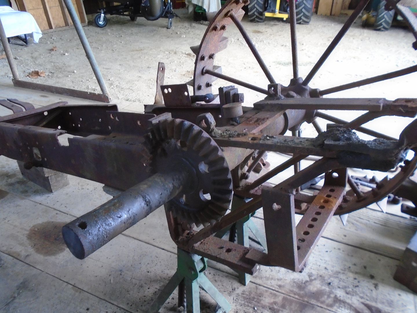
I managed to get the retaining pin to move in the rear axle.


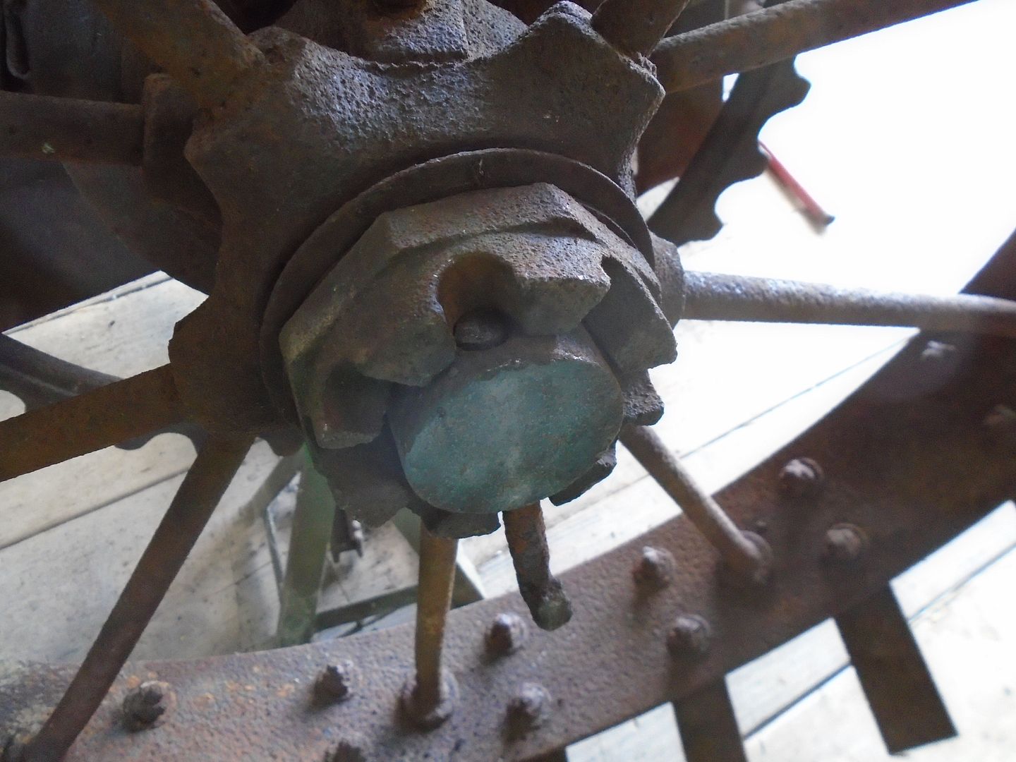
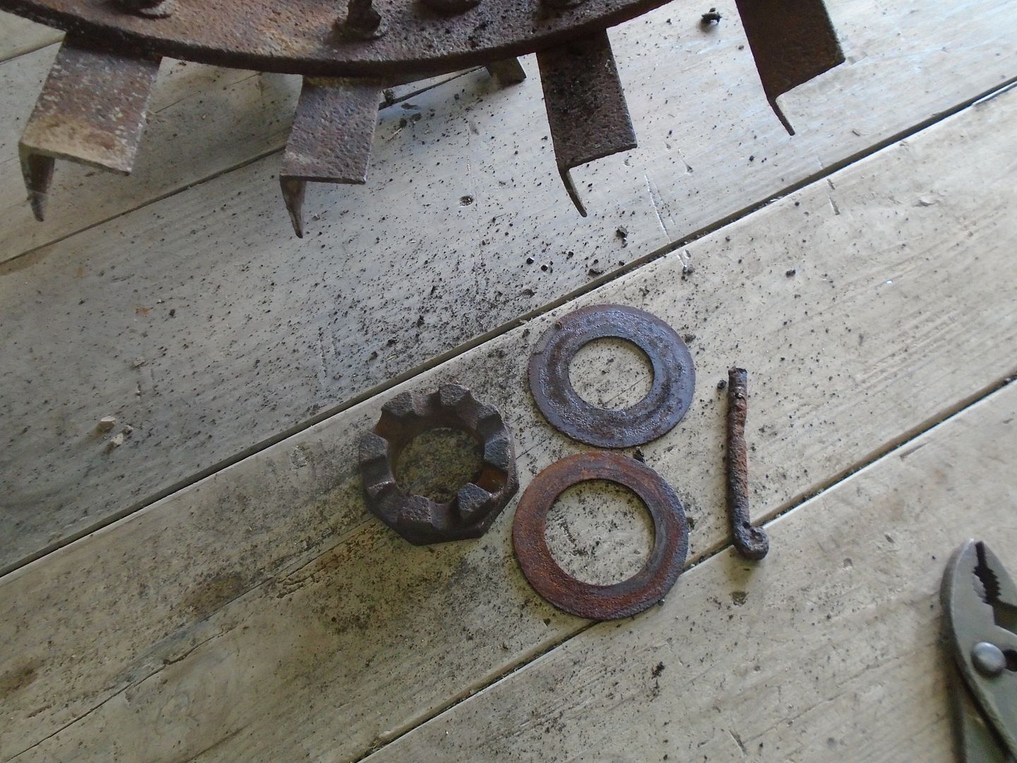
And was able to remove the spacing nut and the washers without any trouble.

This is not a threaded nut, it has three pin grooves machined into it and each one is at a different depth from the face of the nut.
You set the clearance for the ring and pinion gears and then rotate this spacer nut until one of the pin grooves lines up with the hole in the axle.
Then you put the pin in place to hold the wheel on.


This wheel has a grease cup on it and there was enough grease still inside the hub to keep it from rusting to the axle so it slid right off.


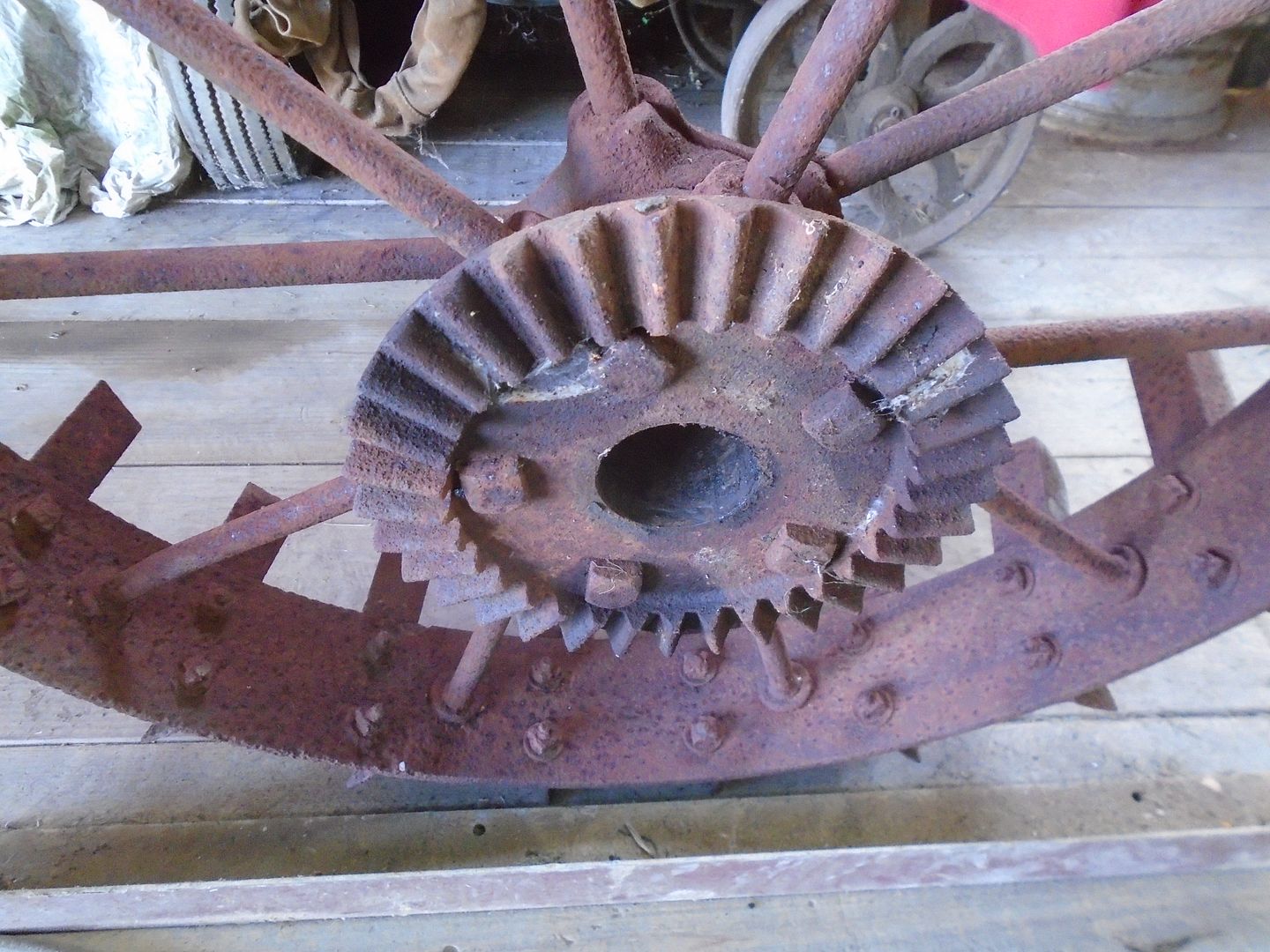
I was glad to see that none of the teeth are cracked or broken on this half of the ring gears.


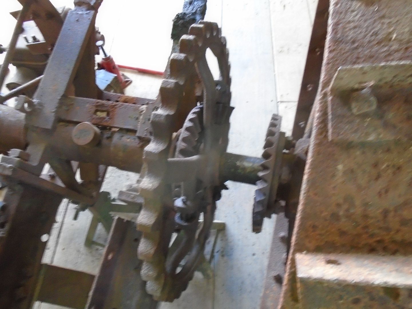
The sprocket does not have a grease fitting on it like the wheel and it took some time to get it worked loose.


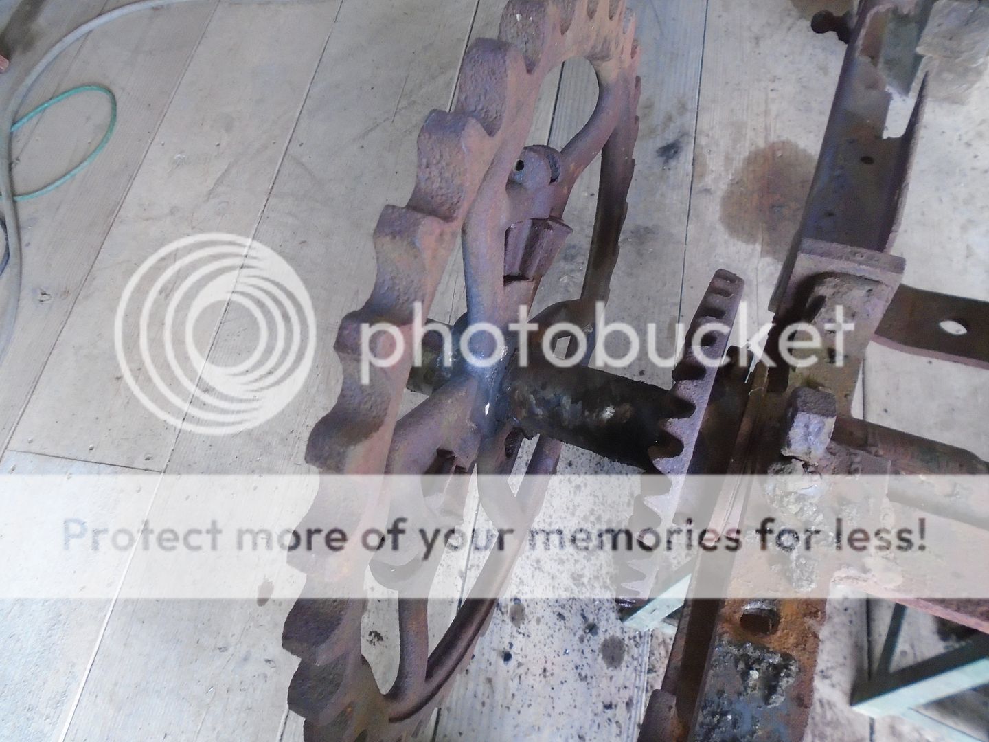
Again, I'm glad to see that there are no broken teeth on this half of the ring gear too.
The axle turns freely in the housing so this is as far down as I'm going to go with this rear end.
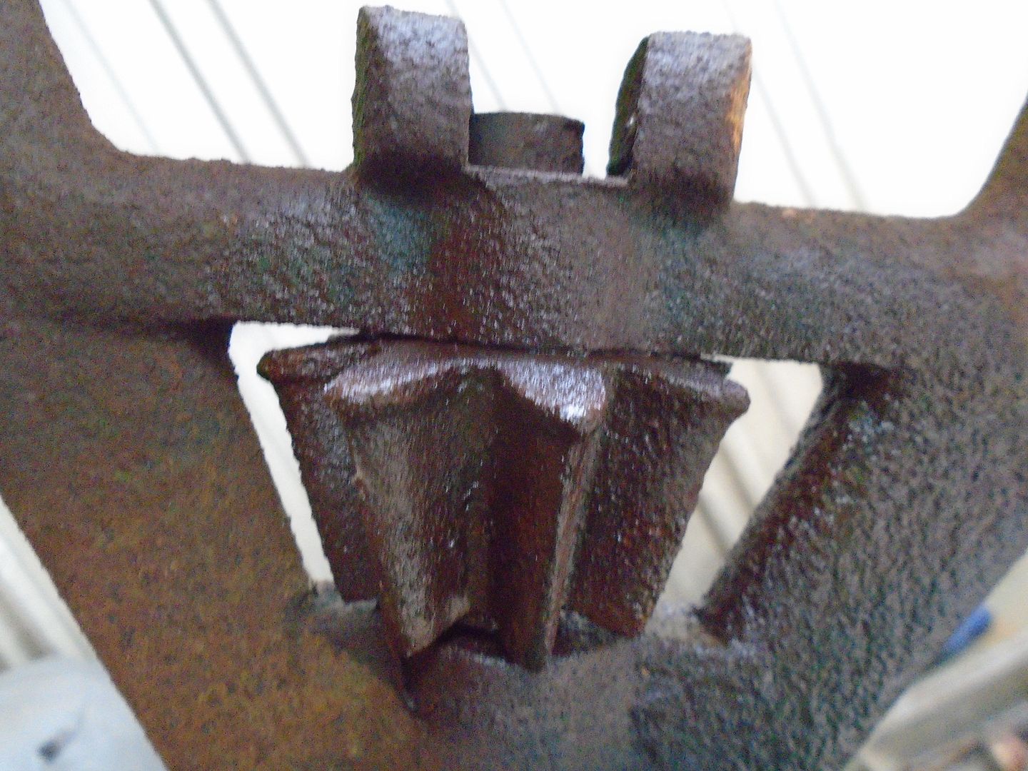
I'm working with cast iron that is anywhere from 94 to 96 years old and it was most likely not a high grade cast iron to start with, not like you will find in more expensive tractors and in cars.
I consider myself extremely lucky that I haven't already cracked or broken anything with all of the heating and hammering that I've been doing on it.


I clamped the sprocket up in the vice to work on getting the pinion gears loose.


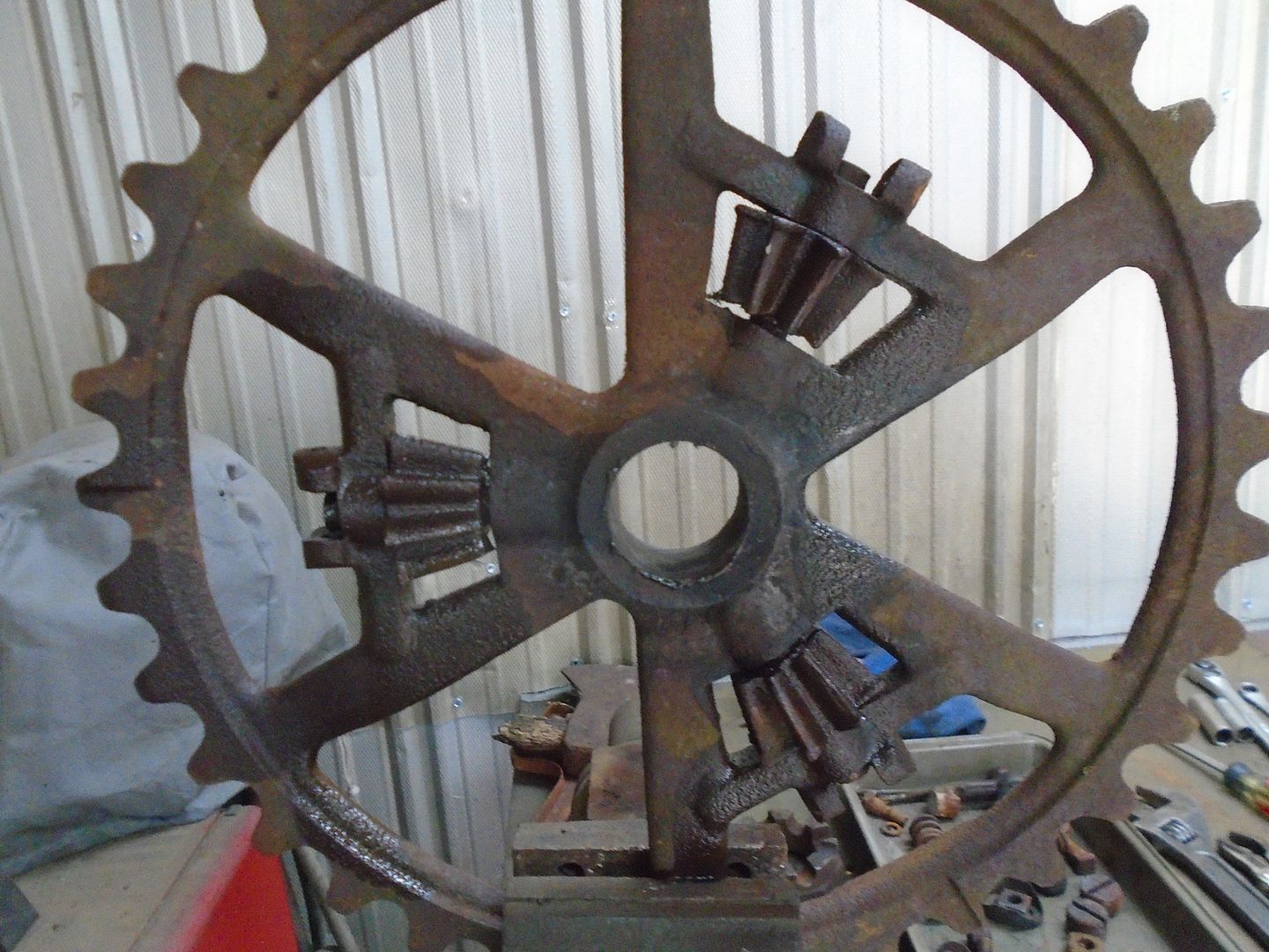
The pin that holds them in place is put into a blind hole so I can't get to the other end of the pin to use a punch to get them out.
I have gotten the gears to rotate but the pins are rusted into the gears so it is the pins that are rotating in the housing and not the gears rotating on the pins.

I have decided to leave them this way.
These pinion gears only rotate when the tractor is making a turn and the inside wheel needs to go a little slower then the outside wheel.
The pinion gears themselves don't rotate very much at all to allow the tractor to make the turn and with this tractor just being taken to tractor shows, these gear pins will never wear the holes out in the casting.


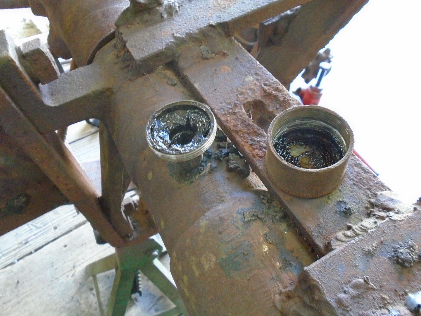
I was also glad to see that the cap came off the grease cup on the axle housing without any problem.

 
I removed the rear axle from the frame this morning.

This is the position it will be mounted in on the frame when I rebuild this tractor.
The mounting brackets will bolt to the underside of the frame and the frame rail will have slots milled into it so the axle can be slid forward or backward to adjust the tension on the drive chain.

The the end was broken on the right mounting bracket so it will have to be welded back on.


The brackets for the draw-bar hitch were removed along with the two ball brackets for the radius arms from the front axle.


This is what is left of the frame and it will be going to the scrap yard.
I'm going to build a new frame using the same U-channel that I built the frame out of for the R/T tractor.

 
I can't imagine those final drive gears not squeaking and grinding.

You have to remember that those pinon gears only move when the tractor is making a turn and then they will be moving slowly and they only have to move enough to make up the difference between the rotation of the two wheels.

Still, as you said, I'm sure they will make some noise but I would expect it to be quieter then the tracks on my crawler.
 
Last edited:
When I was a kid my Dad had a wire tie Oliver baler huge machine, the bull gears that powered the plunger and packer arm were 4 + ft in diameter and you could hear them for a mile or more the way to quiet them down was to use a bar of homemade laundry soap on the gears and it did make them quieter
 
The ends of pieces of the broken axle mount are cleaned up and a piece of steel is clamped in place to hold the pieces inline.


The broken end is welded on and then a piece of flat steel is welded onto the bracket to reinforce it.


The surface of this mounting bracket that will fit up under the frame is ground off smooth.


The hub of the sprocket doesn't have a way to grease it other then excess grease from the axle housing and the wheel seeping into it so I added a grease cup fitting to it.


I ground a groove around the inside of the bore so the grease can spread all around the axle easily.


The sprocket and wheel are assembled on the axle and the hub tension nut is mounted with a new locking pin.


Here's how the new grease fitting looks between the two ring gears.


I held the other wheel still and rotated this one some and the sprocket with the ring and pinion gears rotated like it should ( note the relationship of the grease cup on the wheel and the grease cup on the sprocket in the two photos ) .


View of the axle from the back.

 
When we moved down to Madison, Indiana, I hadn't planned on building any more tractors and I have actually sold some of my tractors since we moved here.
However .. under the circumstances .. I'm glad that this tractor became available to me now because it gives me an interesting and challenging project to work on and it helps take my mind off other things.

.......................................................................................................................................................................

So ... for those of you that may have missed my previous post looking for information .. I'll start here at the beginning.
This is what is left of a small tractor that I picked up at the last show I was at.


I had no idea of what it was when I got it and I have since learned that it was originally a Centaur, 2-wheel, walk-behind garden tractor that was built from 1923 thru 1925.
This is how the design of the tractor looked from the factory.


Some one had converted it into a riding tractor a long time ago and I'm going to rebuild it as a riding tractor.
My son gave me this 9HP Briggs & Stratton engine that was built in 1957 and I'm going to use it to power this tractor.


The input shaft on the transmission is in the front and it had a clutch between the engine and the transmission.


I want to put the Briggs engine inline like the original engine was and I need to make a clutch system for it so I picked up this flywheel and clutch parts off a Farmall Cub to put on the Briggs engine.


I'm using a piece of 3" diameter steel to make the flywheel adapter out of.
This is chucked up in my lathe and both ends have been squared off.


Then I bored it out to fit on the Briggs crankshaft.


It fits snugly onto the crankshaft.


And it also fits snugly into the back of the flywheel.
The Briggs engine has a starter/generator on it already so I removed the starter ring gear from the flywheel.


The crankshaft sticking out the back of this engine does not have a keyway in it so I need to come up with a good way to lock this flywheel adapter so it won't spin on the crankshaft.

I have four 3/8-24 setscrews that have a pin boss machined on the end of them and three regular setscrews and I'm going to use them to lock the flywheel onto the crankshaft.


First I drill and tap three holes on the end of the adapter that goes toward the engine.


Then I turn the adapter around and drill four holes that are .002 larger then the diameter of the pin boss on the set screws.


The adapter is slid onto the crankshaft and tightened down with the three setscrews.
Then the four locating holes are drilled into the crankshaft.
I'm using spacers on the drill so all of the holes are drilled to the same depth.


The pin boss on the ends of the setscrews will set down into these holes and keep the adapter from rotating on the crankshaft.
When I tighten the seven set screws in the adapter down onto the crankshaft, I will then screw another set screw down on top of those first setscrews to lock them in place.


The adapter is set back up in the drill press and the four holes are then drilled out and tapped.

absolute credit to you for your engineering and workmanship , will enjoy the following this project
 
Hi JD, I'm curious were the spider gear free of did you have to persuade them with heat, also what rod did you use to weld the ear back on looking good waiting for new update
 
Today I pulled the top off the transmission and the gears look really good.
They rotate freely and the engagement gear slides easily between the forward and reverse gears.


On closer inspection I see that the key is broken on the ring gear and the keyway in the gear is gouged out.


So ... I'm leaving that problem for the moment and will come back to it later.
The shifting lever slides a shaft in and out to change gears and that shaft is frozen up.


There is a threaded plug in the top of boss on the transmission that I assume has a ball and spring that hold the shifter in place.
I learned long ago to go ahead and try to move something before I reach for the hot wrench and in this case it worked.
The plug unscrewed and the spring and ball fell right out.


I clamped the top of the transmission in the vice and used emery cloth to sand the rust off both of the exposed ends of the shaft.
The shaft still wouldn't move so I heated up the housing on each side a little and it soon started moving freely.
The three photos are positions of the shift lever for : forward ...


neutral ...


reverse ...


The transmission had three mounts to fasten it to the frame but one of them has been broken off and that side of the transmission was fastened to the frame by an L-bracket at the front and another L-bracket at the back that was attached to the bolt sticking out of the side of the transmission.

You can see that someone had tried to repair the original mounting bracket using brazing rod but it didn't work.
I'm going to have to come up with a stronger mount for that side of the transmission but I won't worry about that until I'm ready to mount it on the frame. ( as a side note ... I think I may have uncovered some original paint here )


This tractor has absolutely no provision for any sort of braking system.
I picked up this 4 inch drum and band brake set at the tractor show last week and I'm going to use it for a brake on this tractor.


I want to mount it on the drive sprocket but I need to get that sprocket off the transmission in order to be able to fit the drum to it.
The set screw turned freely without having to use any heat.
I tapped the sprocket with a hammer and it seamed pretty solid so I put a puller on it and it started to move without too much effort.


The sprocket and key came off without too much trouble.


Now ... back to the broken key in the pinion gear ....
I took the cover off the left side and removed the bearing.
The shaft would move a little but wouldn't come out.


I took the cover off the other side and there is a thrust bearing on that side.


I can pull the shaft part way out this side and you can see the broken key.


This shaft has a collar on each end that the bearings ride on and the keyway is in-between these two collars.
I have tried using a big brass punch to force the shaft out of these collars and neither one of them will budge at all.
I don't want to use heat on them because that will destroy the temper in them.

I'm stumped ... one of these collars have to come off in order for the shaft to slide out of the gears.
............ Can anyone tell me how to get one of these collars off ? .............


That's enough for today, I turned the transmission upside down to let the oil drain out of it for the night and came inside to post this.

 
Last edited:
Amazing what some oil will do the trans looks good except for the key right now I have no idea on getting those collars off but you got my brain going for now how about a bearing separator and puller I'd give that a try
 
"Winter project"....Ray, you do know it just became fall a couple weeks ago.......LOL, just kidding.

I always love watching your projects, amazing some of the things you come up with and the one off machines you find.
 
The shaft slides out far enough for me to get my bearing puller behind the collar and the outside of the transmission casing.
Using a brass punch and my big hammer, I was able to get this collar to move.


Besides the broken key, the shaft is also warn where the ring gear fits onto it.


Here you can see how the keyway has been gouged out in the bore of the ring gear.


Both the shaft and the ring gear will have to be brazed up and re-machined to their correct sizes.
 
Back
Top