Winter project

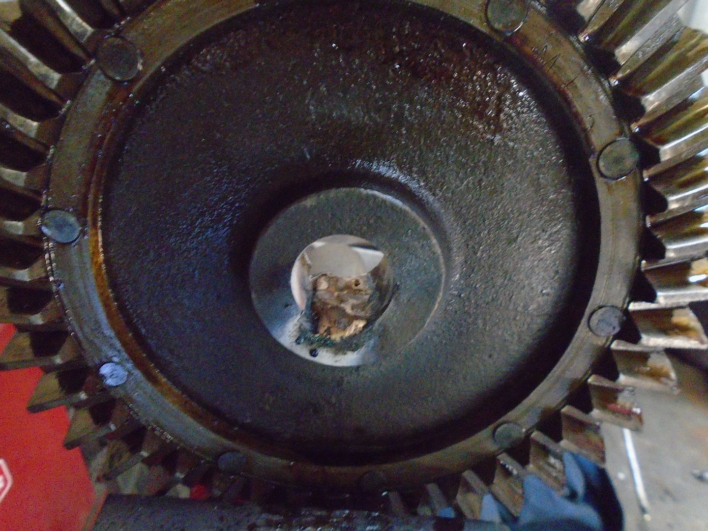
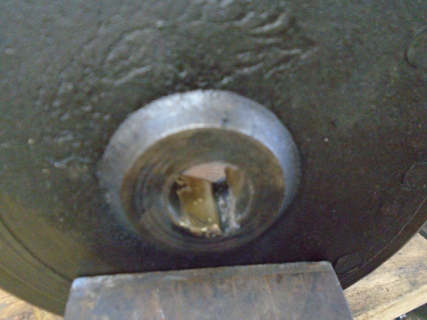
The gouged out area of the bore in the ring gear is built up with brazing rod.


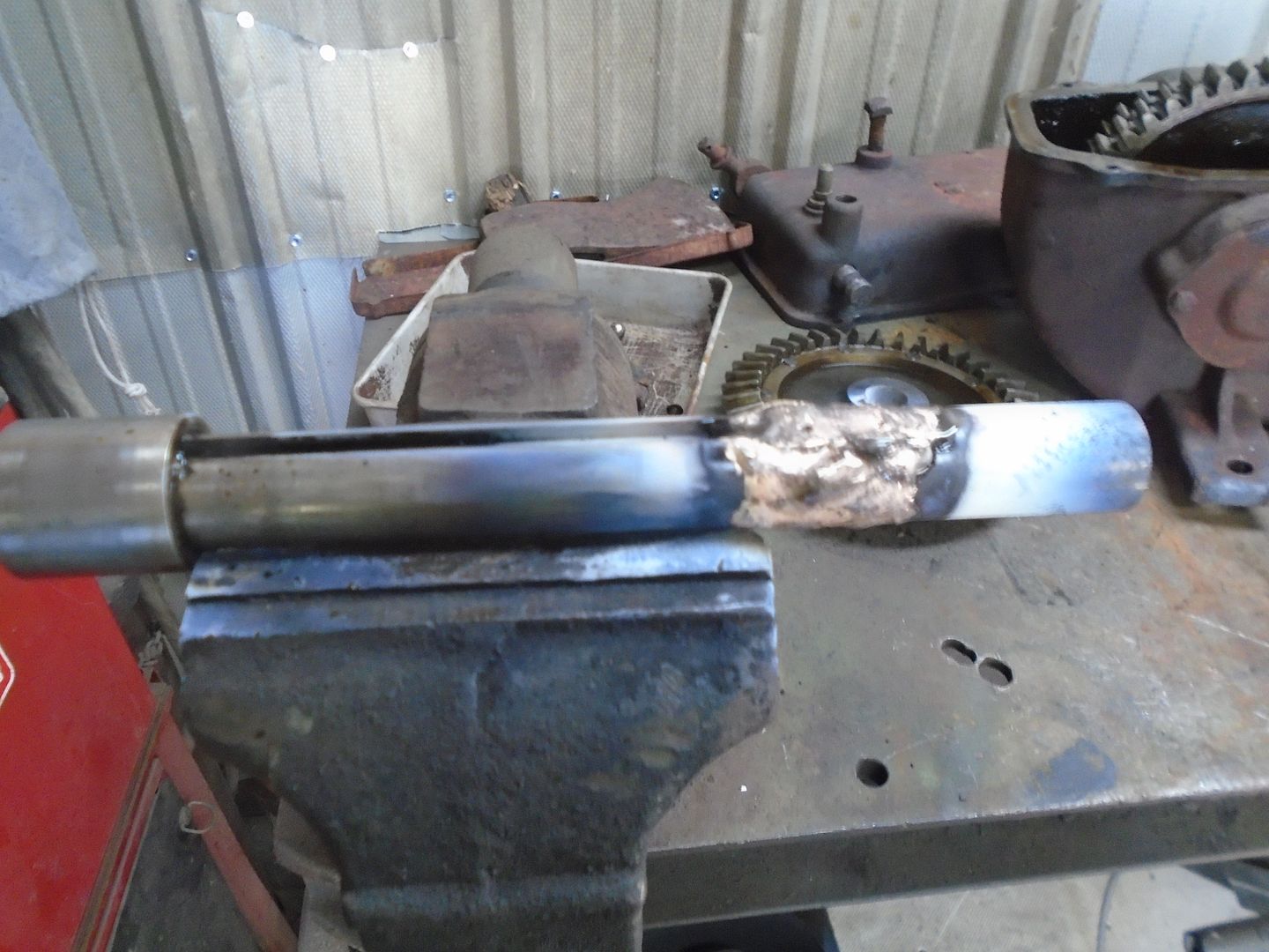
The shaft is built up with brazing rod also.


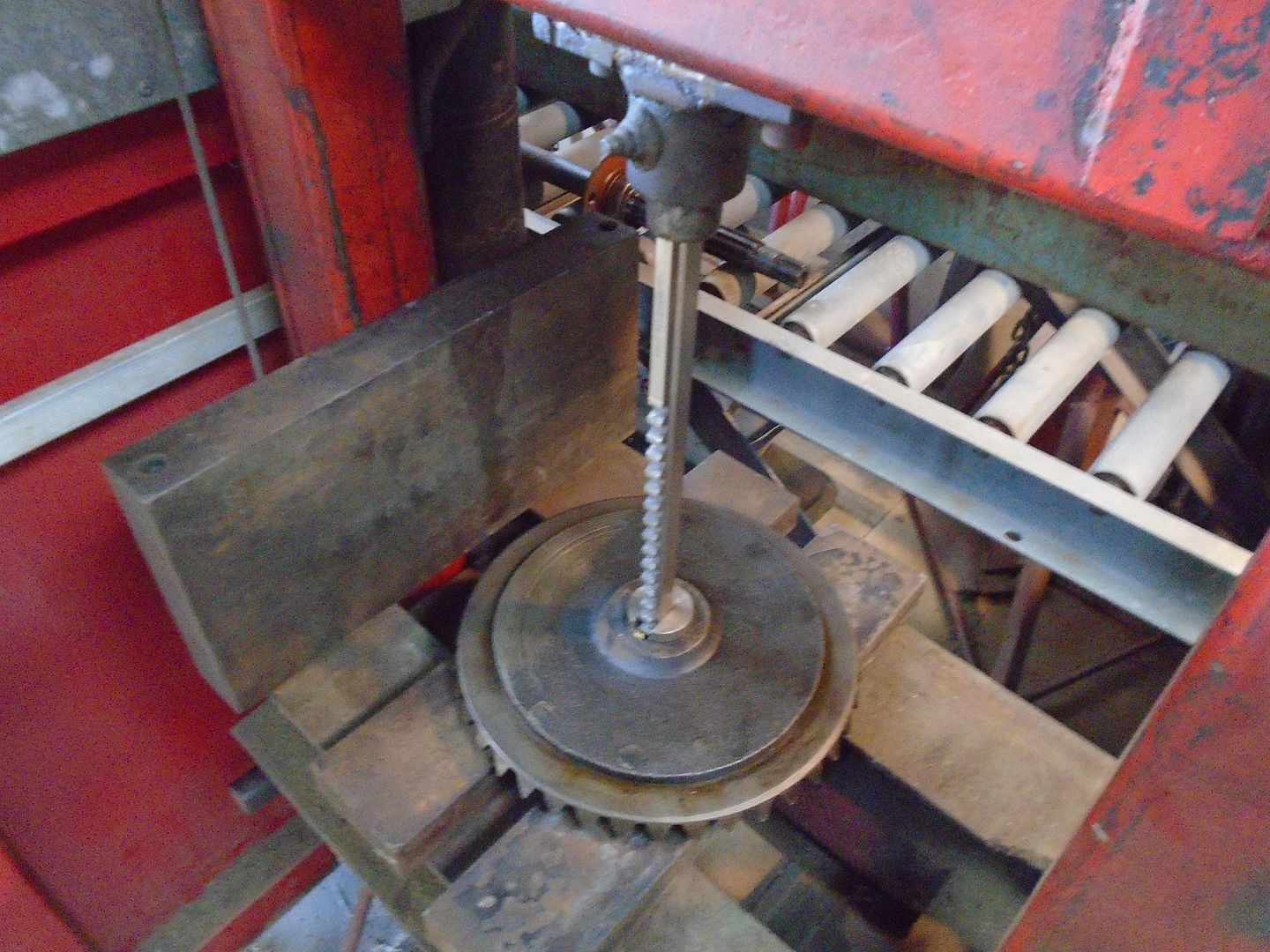
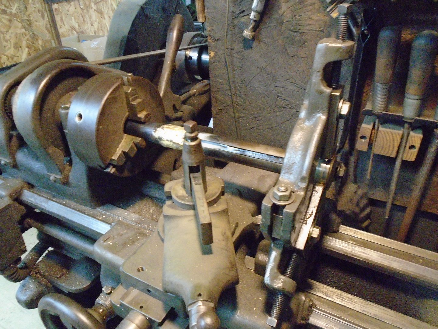
I chucked the ring gear up in the lathe to bore it out to size.
The hole in the ring gear was warn a little so I machined it .010 oversize.


Then the key is re-cut using a key broach.


Here is the finished keyway.


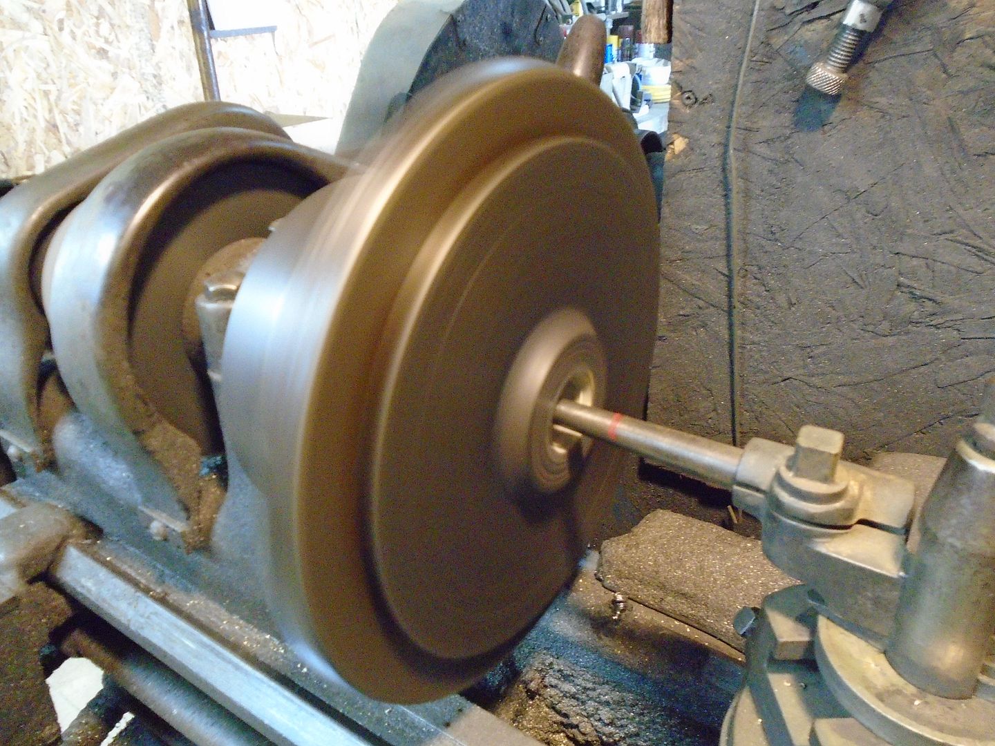
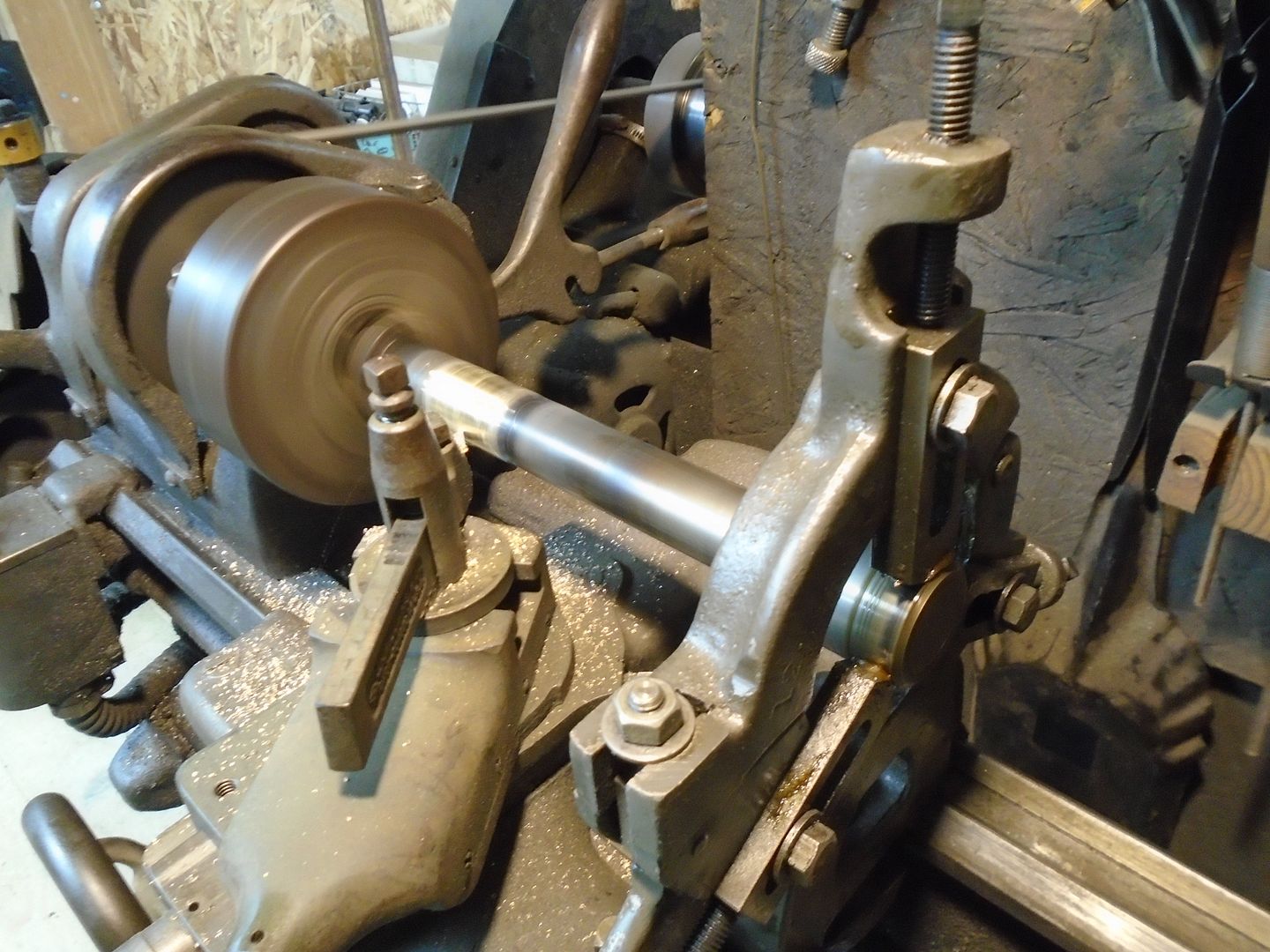
The shaft is chucked up in the lathe.


This is the finished cut on the shaft.
I made it real close to the size of the bore in the ring gear so the gear will have to be pressed onto it.


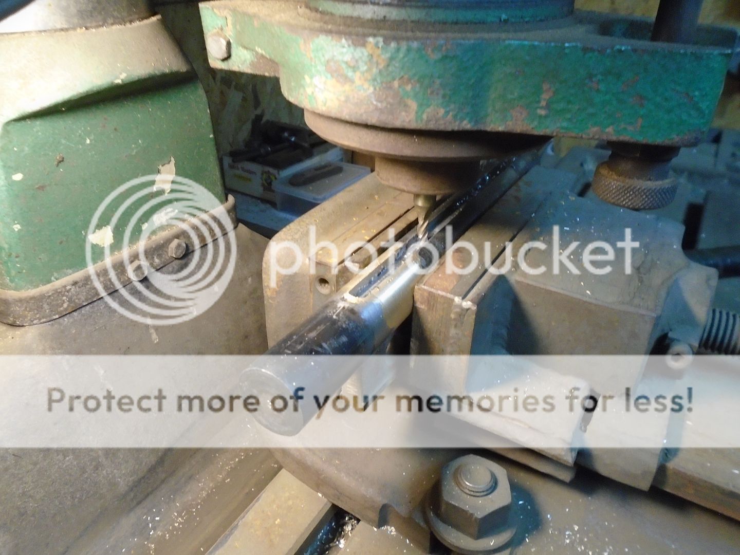
The keyway is being machined into the shaft.


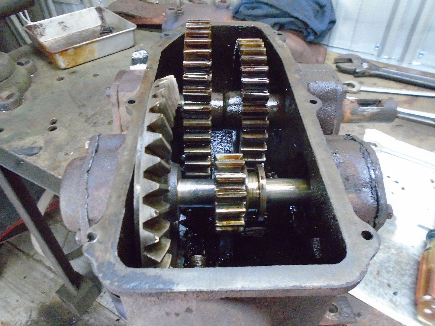
The shifter gear is slid onto the shaft and the bearing collar is pressed back onto that end.


Using a brass punch, the shaft was hammered into the bore of the ring gear.
Then I used a socket that just fit over the shaft to drive the bearing collar on this end.


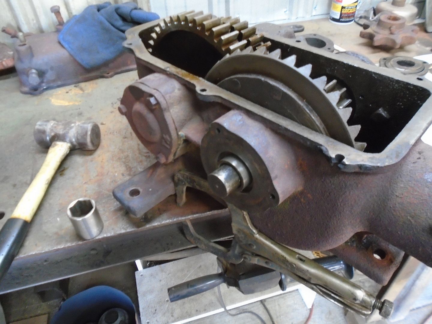
Both end caps are mounted on the sides of the transmission and everything mover smoothly.

 
Time to mount the brake drum on the end of the drive sprocket.
I chucked the sprocket in the lathe with one end held up against the chuck jaws while I tightened them.
When I turned the lathe on, the outside bore was running way out because the ends of the sprocket are not square to the bore.

Here, the tool is touching the end of the sprocket.


Rotating the sprocket 180 degrees and the surface has pulled away from the tool.


I tapped on the sprocket until the bore is running true and as you can see, the surface of the other end has now pulled away from the chuck jaws on one side.


With the bore running true, I faced off this end of the sprocket.


Then I was able to just turn the sprocket around and hold it up against the chuck jaws while I tightened them and the bore stays running true now.
I started facing off this end.


Before I can start machining this end for mounting the brake drum, I need to know how much clearance I have to have for the chain.
So I figured that I would just remove the cotter pins on one link and use it to check for clearance.

I expected the side plate of the link to just lift off once I had removed the cotter pins.
The side of the link doesn't move .... so I put it on the vice and used a brass punch and a hammer to push the pins out.
Nope ... won't budge ... not even with the big hammer.


Now this isn't your average chain that you find on most garden tractors ... the link pins are 1/2 inch diameter and they are 1-3/4 inch ctr. to ctr. and it has to weigh at least 40 pounds.
I put it on my die cart and took it over to the press.
It took a lot more pressure then I expected to get the pins to move.


Once the pins were flush with the side plate, I used a 3/8 diameter dowel pin to press the first pin about half way thru the side plate.


Then I pressed the other pin and the side plate popped right off.


All that fussing around just so I can do this. ( okay .. so I know how much clearance there is between the chain and the sprocket hub now )


I found a step collar in my parts that the brake drum fits on.


As you can see, it will clear the chain.


The end of the sprocket is turned down.


Then I put the collar in the lathe and bored it out.


I made the two parts so they would have to be pressed together.


Here is how the brake drum looks on the sprocket.


Most likely the pressed fit would be strong enough to keep the brake drum on the sprocket.
However ..... my philosophy has always been: You can't build it too strong .. you can only build it too week .....
With that in mind, I went ahead and brazed the collar on the sprocket.

 
Remember this area on the transmission where the mount had been broken off ?
Someone had brazed it up but it still leaked oil.


I ground that down flush with the casting and cleaned the area up.
The transmission is drilled and tapped for 5/16-24 bolts.
The side of the transmission is almost 5/16 inch thick.


Using 1/4 inch thick steel, I formed this patch.


The bend on the patch is sharper then the curve of the transmission so I heated up the corners of the patch and hammered them down to fit the radius on the transmission.


The transmission is set up with spacers under the two existing mounts.
The third mount is set to the same height as the other two mounts and it is clamped in place and ready for welding.
I want to keep this mount as close to the transmission as I can so there is less stress on the areas of the casting where the bolts go thru.


I liberally spread RTV gasket sealer on the mount and bolted it in place.
Once the RTV has dried, I will trim off the excess that was squeezed out.

 
This is how the new transmission mount looks with the excess gasket sealant removed and re-primed.


The input shaft is a little under 13/16 square and it's buggered up pretty good.


I got a 3/4 square impact socket off ebay.
I had figured that I would machine the input shaft down to 3/4 square so the socket will fit on it.
Then I could machine a 3/4 square on the end of the drive shaft to fit into the other end of the socket.

Since then, I have decided to use this jaw coupler with the rubber insert between the transmission and the drive shaft to help cushion drive force from the engine.


The square on the input shaft still needs to be machined down to 3/4.
I clamped it into the vice on the mill and started cutting the square down by .010 at a time.
With the round part of the shaft resting on the bottom of the vice, I cut one side then rotate it 90 degrees and use the machinist square to square up the side that I just cut.
I do this with all four sides without changing the depth of the endmill.
This way, the square stays centered on the shaft.


I keep doing this until the socket fits onto the square shaft.


The round part of the shaft was worn down enough so that the hardened bearing collars turned on the shaft.
To correct this, the shaft is chucked up in the lathe and a knurling tool is used to press grooves into the shaft surface and the raised edges of the grooves increase the diameter of the shaft.


Then the bearing collars are pressed onto the shaft.


They put a thrust bearing on the shaft that holds the ring gear but they only put two washers together to support the thrust on the pinion gear.
The two washers at the bottom of the photo were behind the pinion gear.
You can see that the center area is worn into the round washer where the pinion gear washer rubbed against it.

I have gotten a thrust bearing that I'm going to use instead of the two washers.


The input shaft is put back into the transmission and you can see the thrust bearing tucked down into the housing behind it.

 
The impact socket is put on the lathe and turned down to where the jaw coupler fits onto it.


I got a little ahead of myself here ... the end of the socket needs to be sealed off so the transmission oil can't come out of it and I should have done that before I turned the outside down.

The 3/4 square hole is blocked off with a piece of metal pressed into it.


And the end is brazed up.


The socket is then clamped in the mill vice and the keyway is milled into it.


The key is a tight fit and is set down into the groove with a light tapping with a hammer.


The socket now fits smoothly into the jaw coupler.


Finally the finished socket is installed onto the input shaft of the transmission.
It is held in place by a 1/4 inch allenhead bolt.


With this socket adapter, the jaw coupler will now fit on the input shaft of the transmission.
There is an end cap that bolts onto the transmission but I have to do some more modifications before that can be bolted on.

 
A lot of our gearboxes and pumps at work use couplers like that. Lovejoy brand. They are super durable and work great when getting alignment down to the ten-thousanth's just isn't possible. Very creative using the impact socket for the hub!

DAC
 
Do the gears on the inside of the tranny have a similar amount of wear compared to the shafts? Any issues there? (last pic in post #51)

The rest of the gears are in pretty good shape and the bearings on the shaft that the big forward and reverse gears are on are still tight.
It seams to me that as the two thrust washers behind the pinion gear wore down, it let the input shaft start to wobble and this set up a hammering motion between the ring and pinion gears.

 
This flange bolts onto the input end of the transmission.


Turning it over, there is a thick washer inside it.


Under the thick washer is a fiber grease seal.
It looks to me that this was to seal against the outside housing of an enclosed driveshaft and not against the spinning driveshaft itself.


I need to come up with a way to seal against the rotating input shaft.
I found an oil seal that fits the diameter of the socket on the input shaft.


Right now, this socket is held onto the input shaft with an allenbolt with the bolt head and the lock nuts sticking out past the surface of the socket.
The oil seal is going to have to sit back far enough so that the back of the seal will be over the area where the allenbolt is.
I ground the head of the allenbolt down to where there is just a narrow part of the head that now fits into the groove on the socket.
Then I milled a flat spot on in the groove on the other side of the socket for clearance for a cotter pin.


As you can see, both ends of the allenbolt are now below the surface of the socket.


And there is now plenty of clearance for the back of the oil seal.


The old flange is not thick enough to put the oil seal right into it so I'm going to have to add some metal to it.
Here I'm cutting off some of this round stock.


The center hole in the flange is a machined hole but the counter bore on the back side is just cast into the flange and is not concentric with the center hole.
The flange is chucked up on the center hole and the counter bore is machined out until it runs concentric with the center bore.


Then the flange is turned around and held on the counter bore so I can machine the center hole larger.


Once the flange is to the size I want it, I put that piece of round stock in the lathe and machined it down to fit into the flange and squared up both faces.
Then I tapped the flange onto it and squared up the face of the flange while it was still on the lathe.


The flange is brazed to the round stock on the back side.


Here's how it looks from the front.


The flange is put back on the lathe and the center is machined out to the size and depth needed for the oil seal.


The oil seal is pressed into the flange and it is mounted onto the transmission.


Then the coupler is installed.


I also put the sprocket and brake drum back on.
I found a plastic cap off a spray can that fit tightly over the center hub to make it look more finished.

 
Back
Top