
You are using an out of date browser. It may not display this or other websites correctly.
You should upgrade or use an alternative browser.
You should upgrade or use an alternative browser.
Winter project
- Thread starter jdcrawler
- Start date
Any progress lately?
Not on the tractor.
Before we were able to move down here I had already moved all of my stuff down and it was stored out at my son's place.
Little by little I have been getting things out of his place and bringing them to my place.
We have been waiting for the weather to be cool and dry enough to move two of the bigger items and we were able to do that a couple of weeks ago.
The first one is this old U-haul truck that I now have sitting out behind my garage for additional storage.
I have it sitting so the back bumper is resting on a treated 2x8 and I put a door in the side for easier access.

The second one is this 1946 DIVCO milk truck that had a lot of things stored inside it.
I've got it emptied out now and I'm getting ready to put the milk truck up for sale.

Neat old milk truck.
Sure is! I often wish I could have some sort of project old car/truck, but they cost so much to build.Neat old milk truck.
The weather here has been in the 50's off and on so I have been able to spend some time over the last few weeks working on the tractor.
Photobucket has finely got their site back up and working again so I can now start posting again. .................
Next on the list of things to do was working on the front axle.
Like everything else on this tractor, I had to use the hot wrench to take it apart.
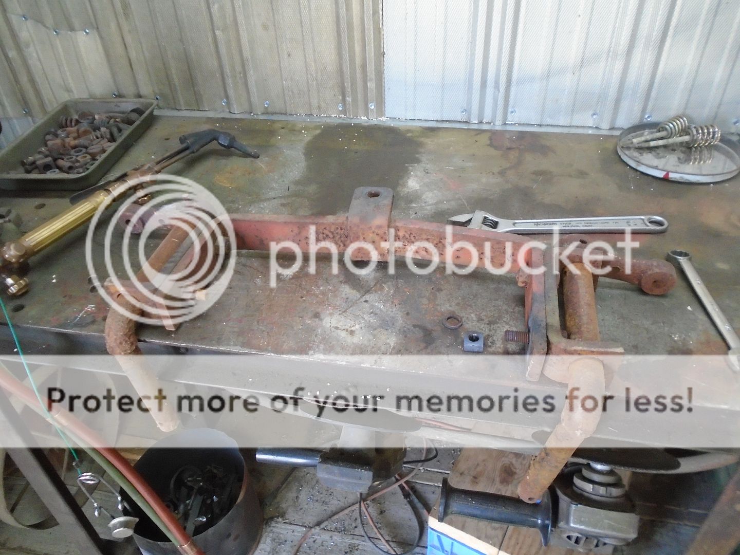
The steering arms have been welded to the top of the axles.
I set the axles up in the mill to cut this weld off.
I mill them down to where the end mill is just starting to cut into the steering arm.
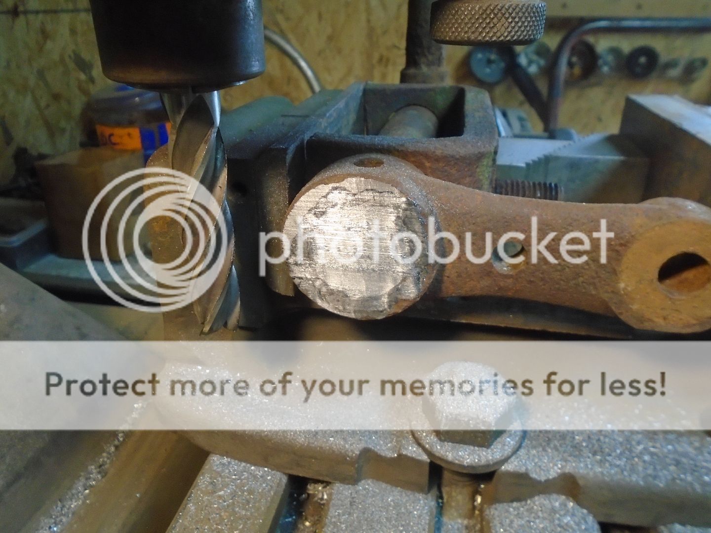
What weld that is left is thin enough that it is easy to knock the axles loose from the steering arms.
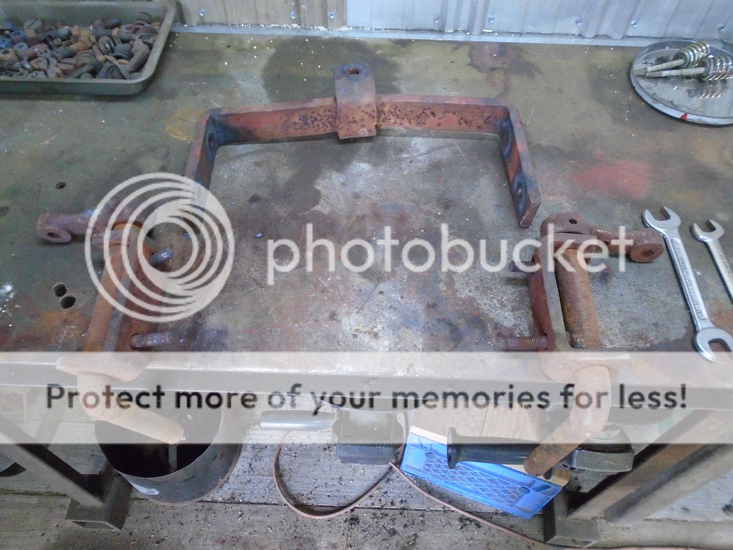
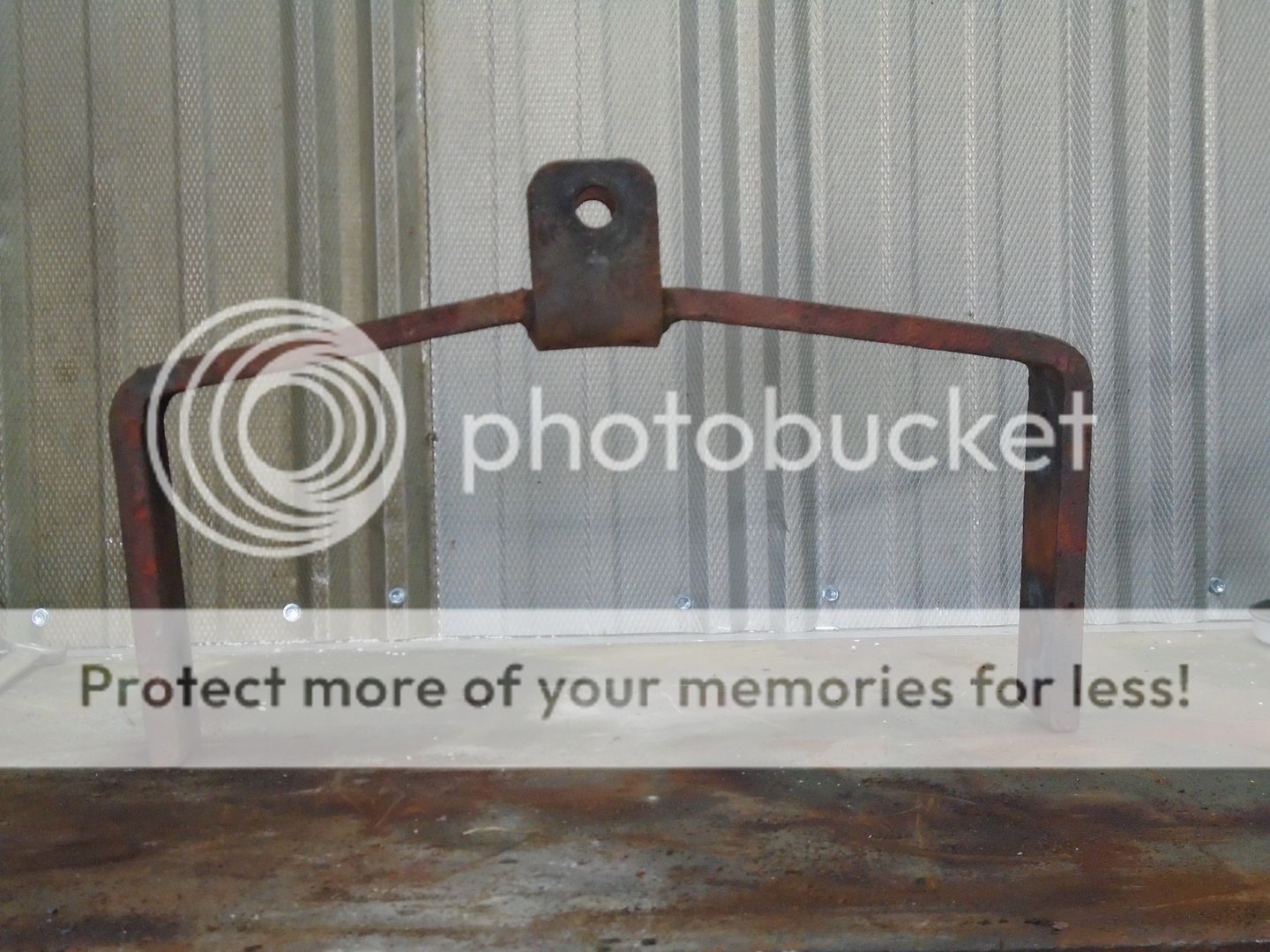
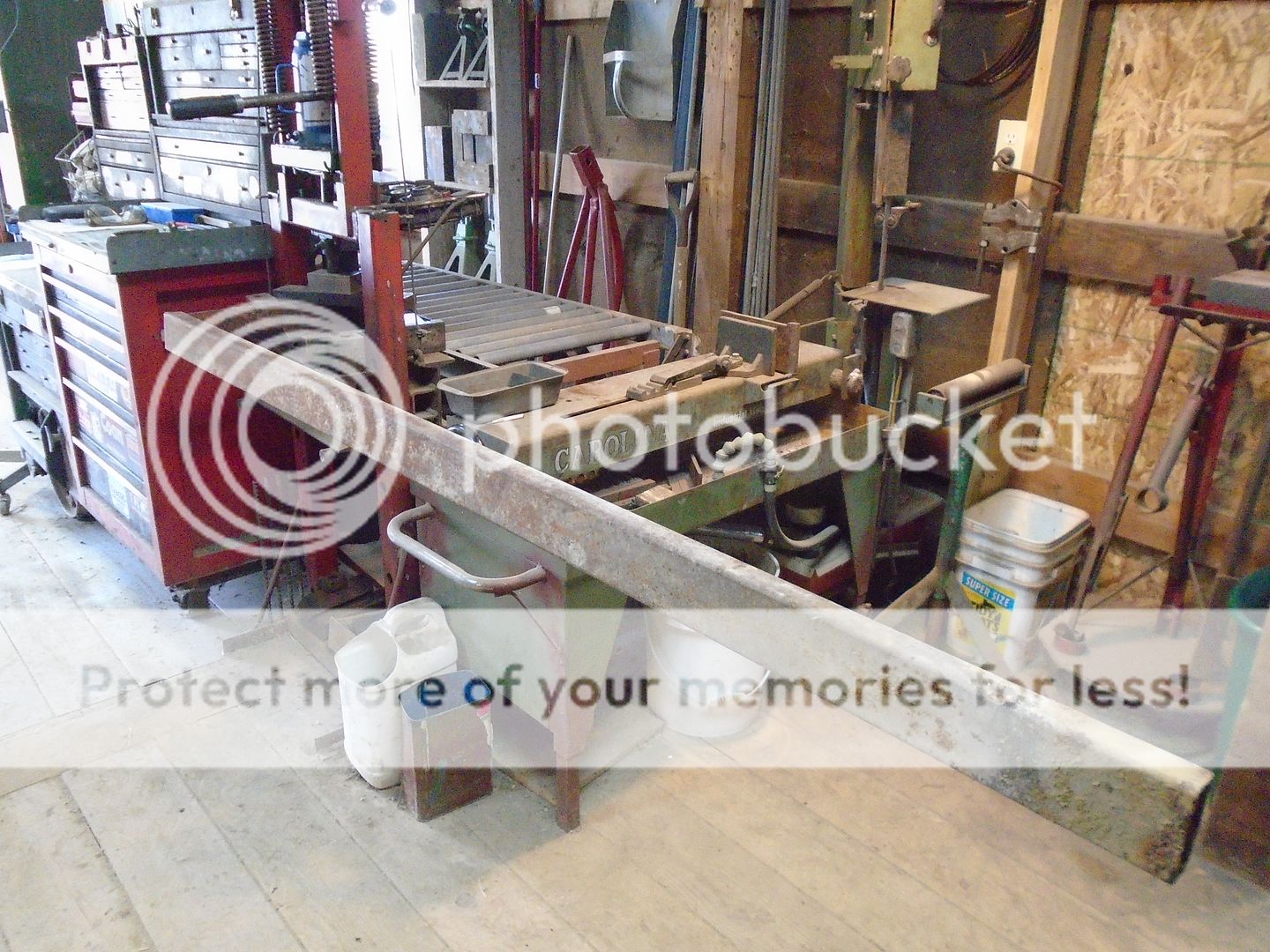
As you can see here, the front axle bar is bent out of shape.
I work on straightening the upper bar first.
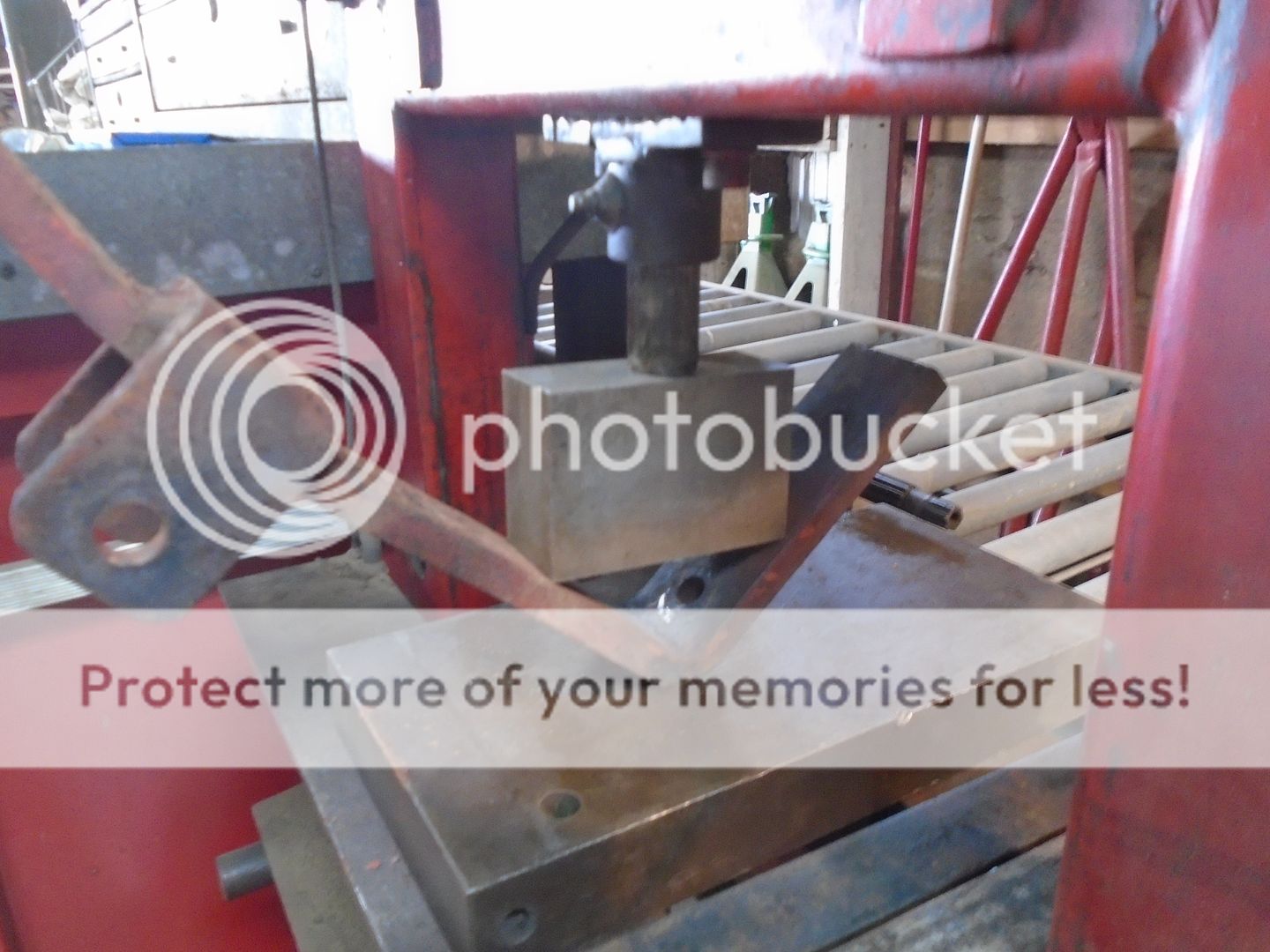
With that straightened out, you can see that angle on the side down bars need some work.
So I use a steel block to correct the angle.
NOTE: if you do this on a press, make sure that you don't stand in front of it because this can very easily slip out and go flying.
Now the axle bar looks better.
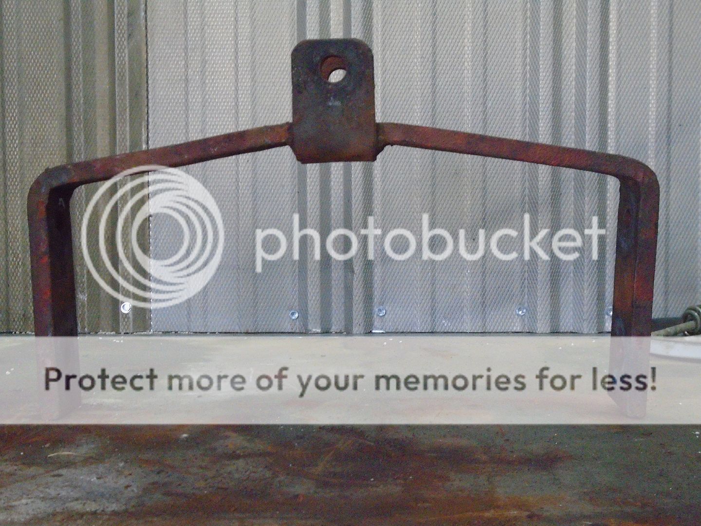
One side of the down bars is twisted off from the other side.
I used the press to hold one side bar down while I put a long piece of steel over the other side bar and pushed down on it to straighten it out.
Now the two side down bars line up pretty good.
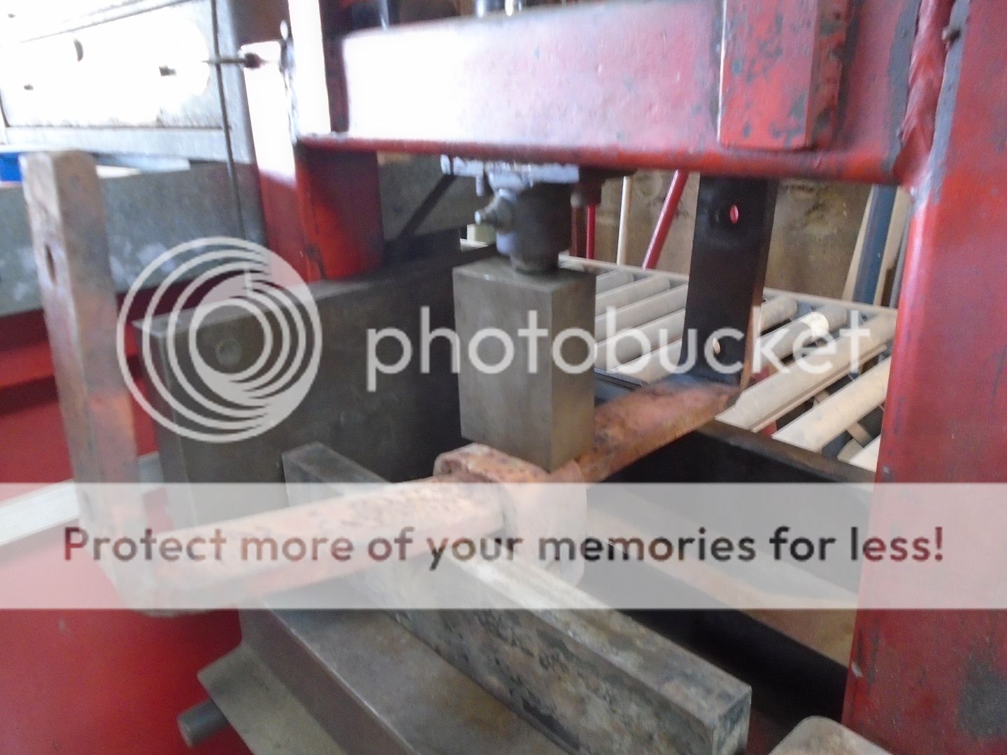
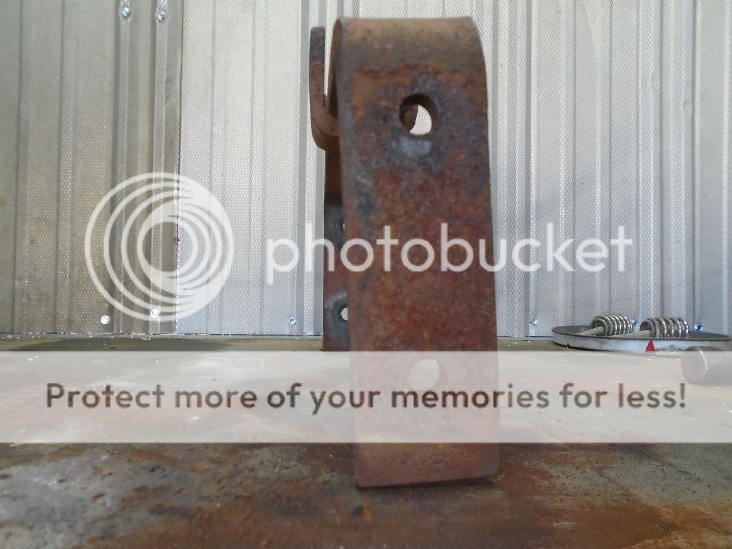
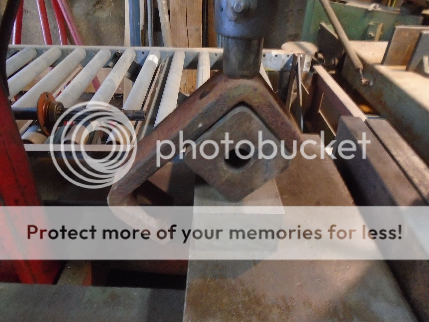
Both of the axle pivot mounts were bent out of shape a little so I used the press again to get them back into shape.
All of the front axle parts were them sand blasted and primed.
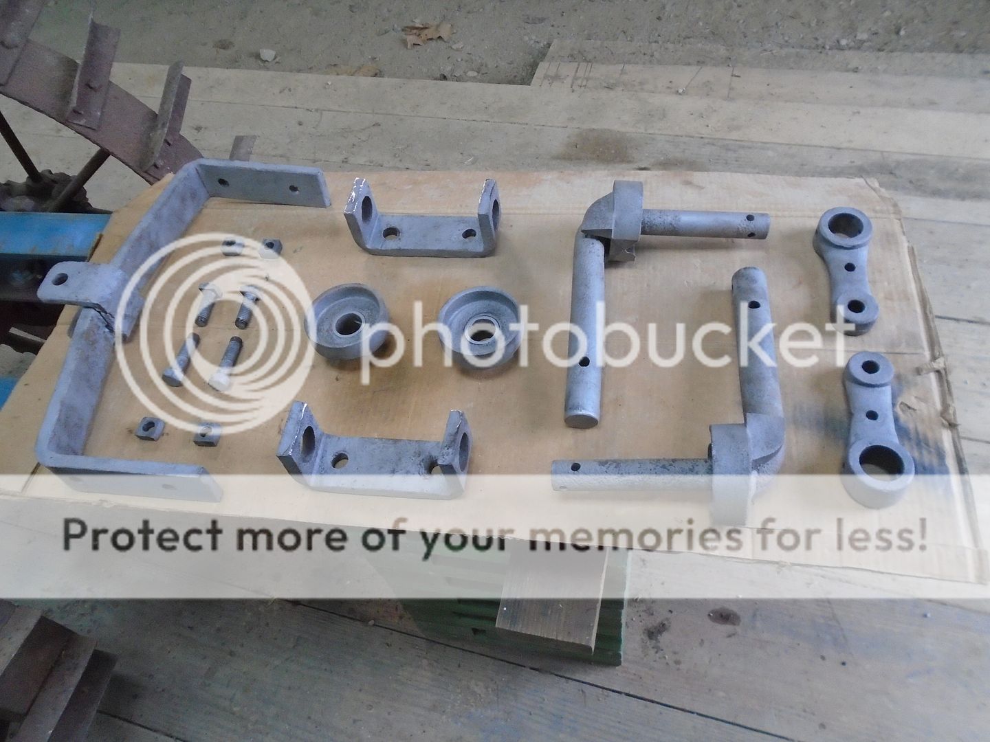
Once the primer was dried, the parts were re-assembled.
Photobucket has finely got their site back up and working again so I can now start posting again. .................
Next on the list of things to do was working on the front axle.
Like everything else on this tractor, I had to use the hot wrench to take it apart.


The steering arms have been welded to the top of the axles.

I set the axles up in the mill to cut this weld off.

I mill them down to where the end mill is just starting to cut into the steering arm.

What weld that is left is thin enough that it is easy to knock the axles loose from the steering arms.

As you can see here, the front axle bar is bent out of shape.

I work on straightening the upper bar first.

With that straightened out, you can see that angle on the side down bars need some work.

So I use a steel block to correct the angle.
NOTE: if you do this on a press, make sure that you don't stand in front of it because this can very easily slip out and go flying.

Now the axle bar looks better.

One side of the down bars is twisted off from the other side.

I used the press to hold one side bar down while I put a long piece of steel over the other side bar and pushed down on it to straighten it out.

Now the two side down bars line up pretty good.

Both of the axle pivot mounts were bent out of shape a little so I used the press again to get them back into shape.

All of the front axle parts were them sand blasted and primed.


Once the primer was dried, the parts were re-assembled.

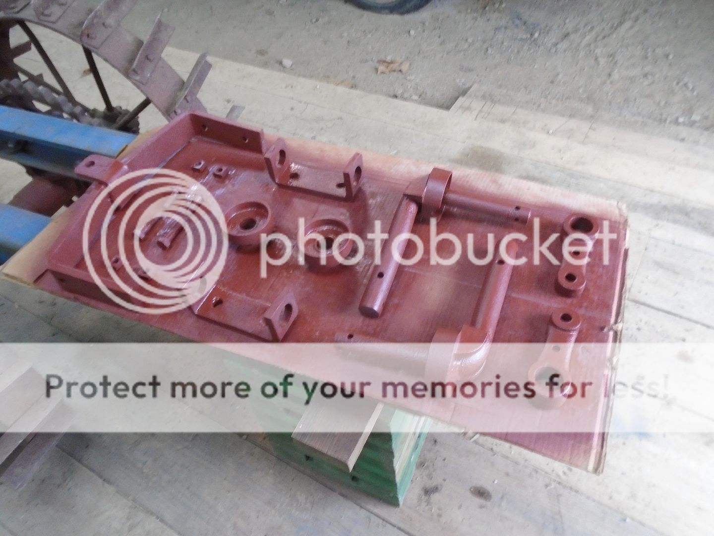
I bore out a piece of round steel and put in brass bushings to make the pivot mount for the front axle.

The front of the frame is then cut out.
And the pivot mount is welded in place.
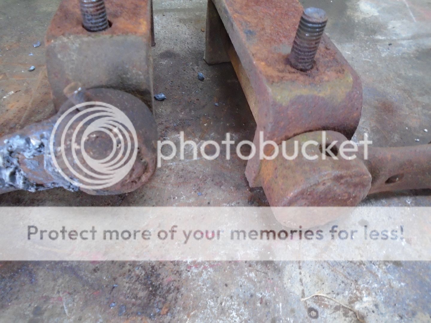
The wheels were mounted on the spindles and the axle assembly is mounted to the frame.
... Note ... the two lower bolts holding holding the spindle mounts to the axle bar are longer then the two upper bolts.
The radius rods will fasted to these longer bolts.
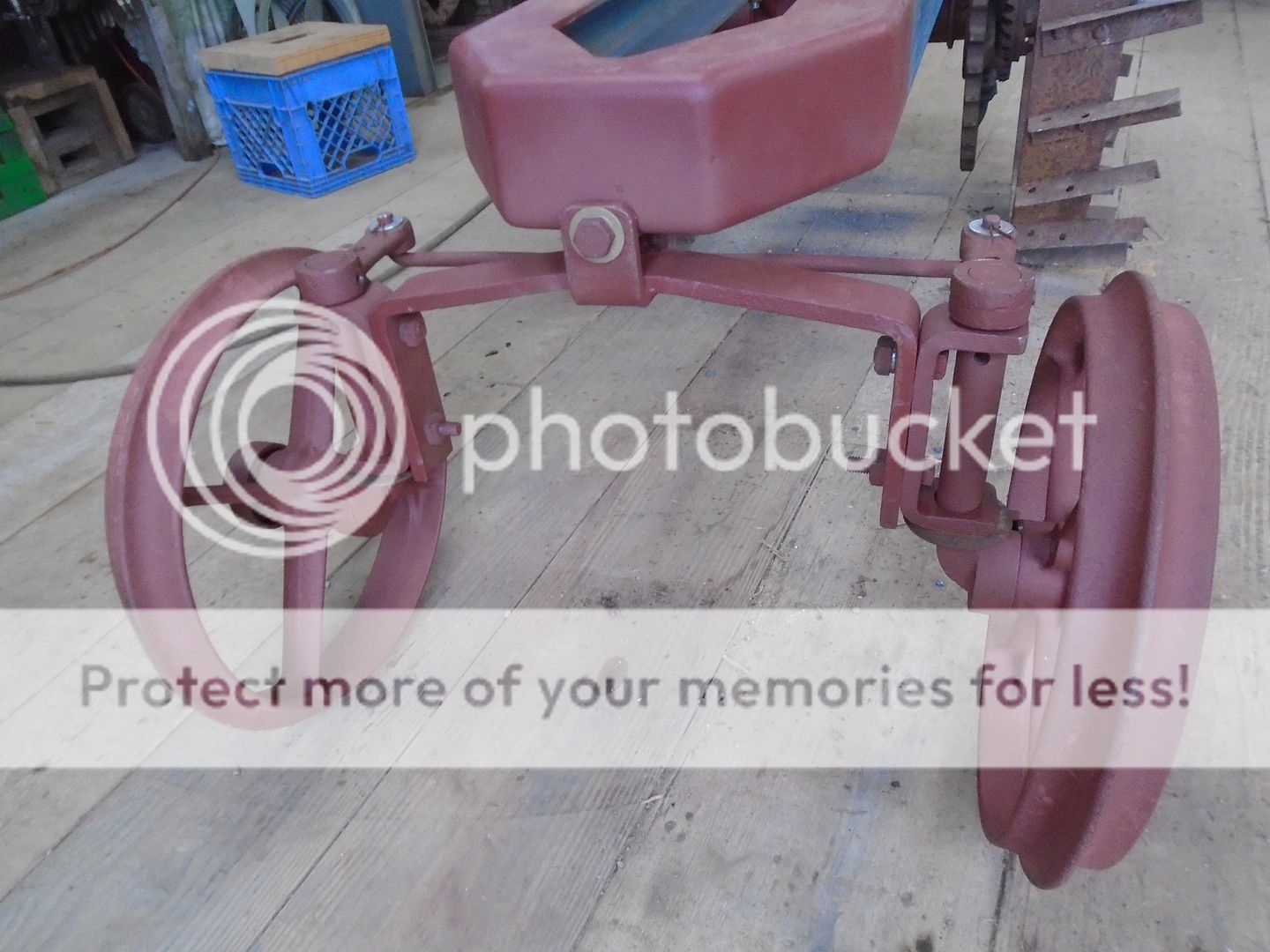
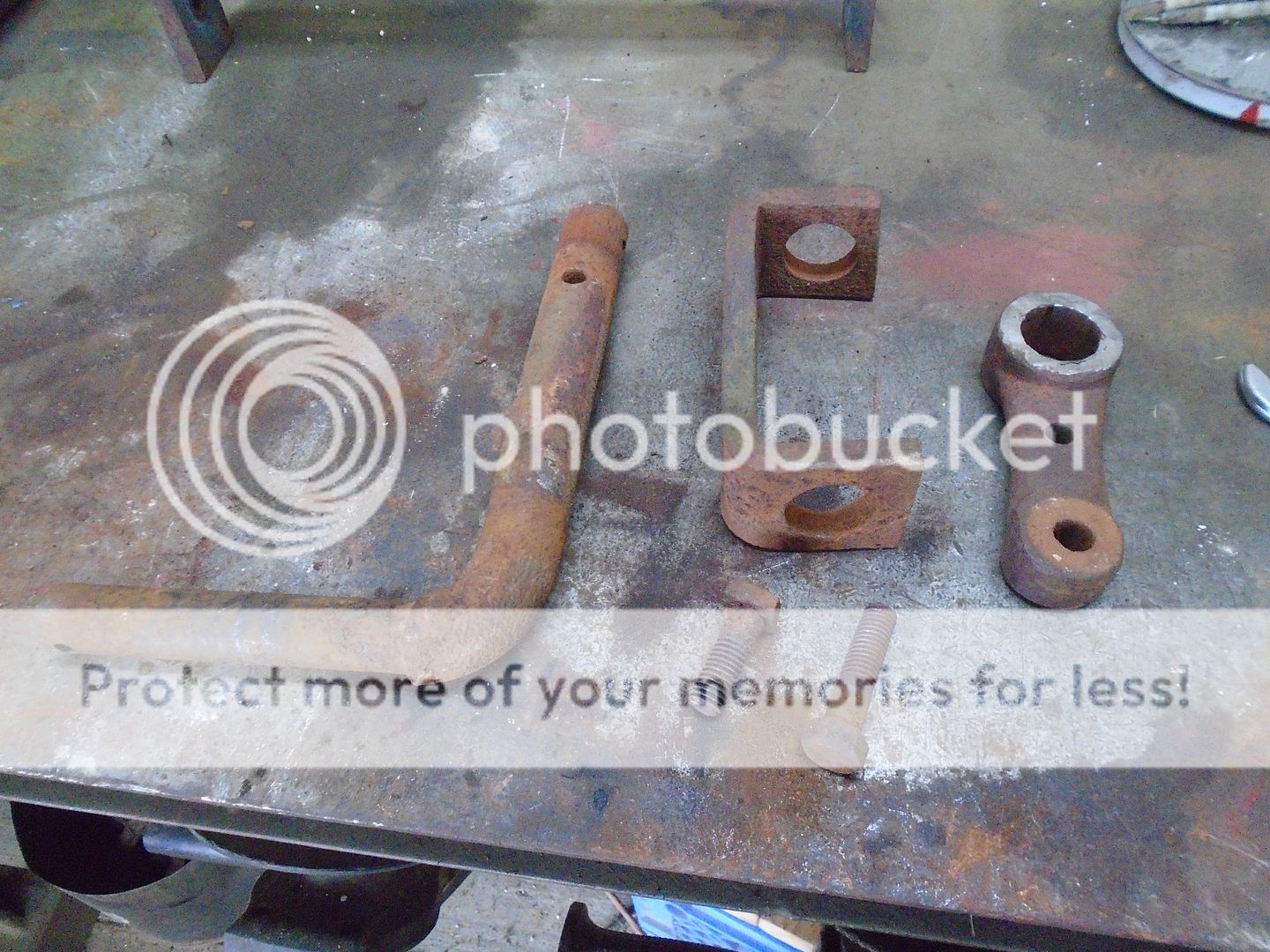
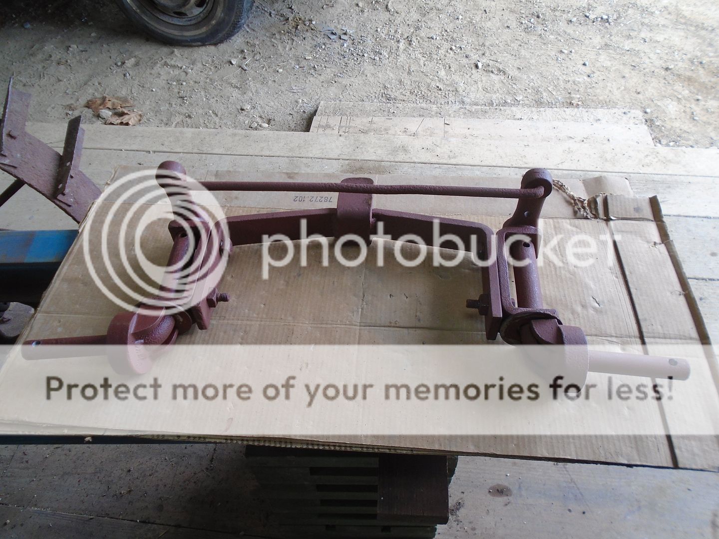
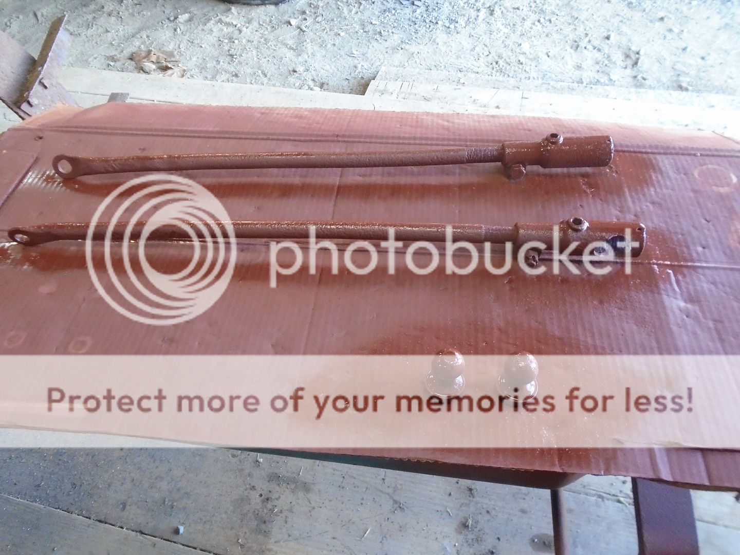
These are the radius rods that keep the front axle from moving backward or forward.
Obviously, they need a little work.
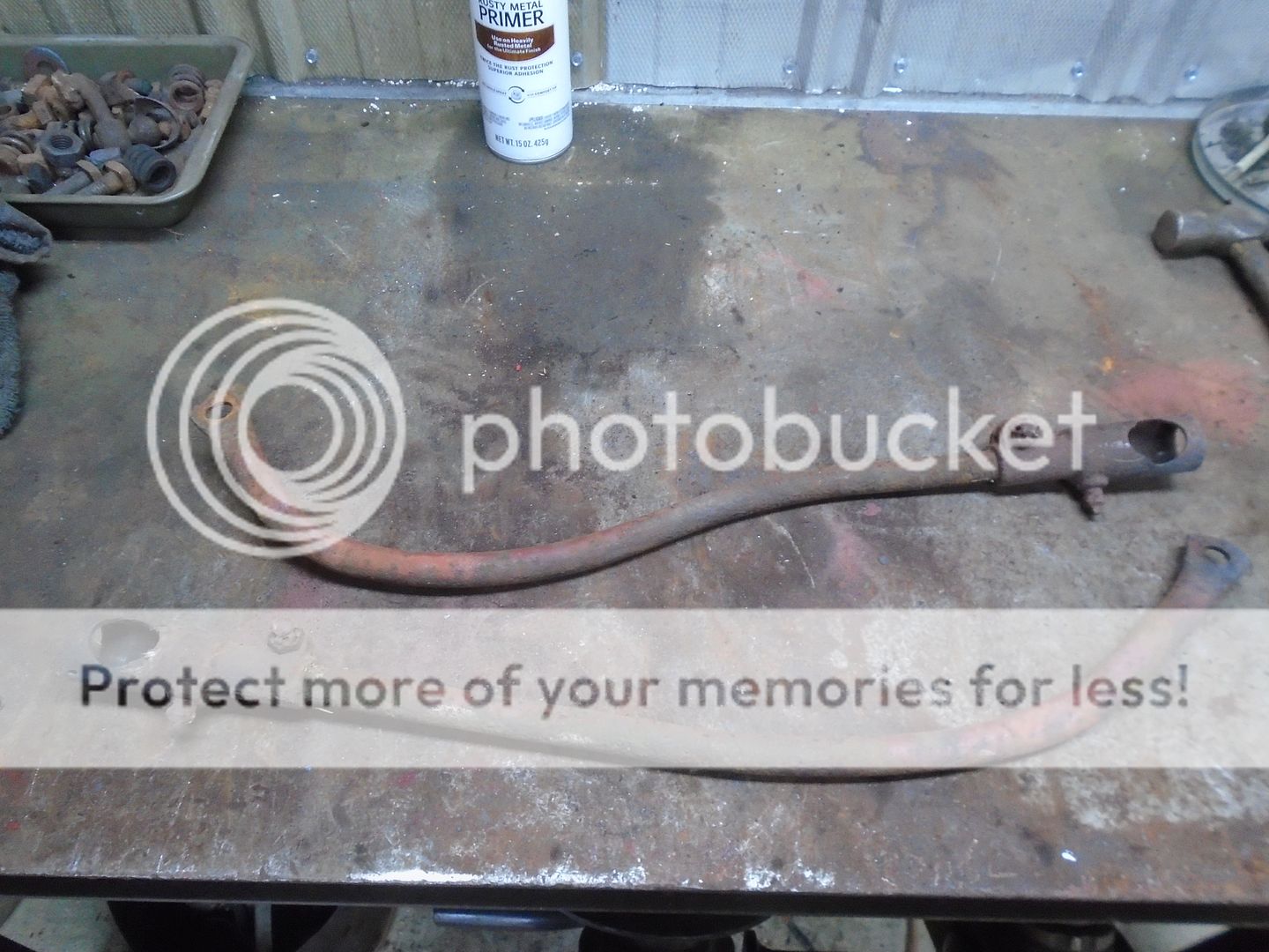
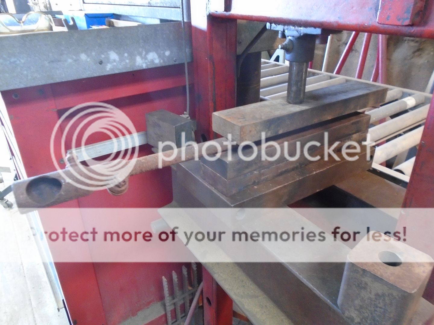
They were straightened by pressing them in between two flat steel bars.
I kept rotating them around as I operated the press until they were straight.
Then they were sand blasted and primed.
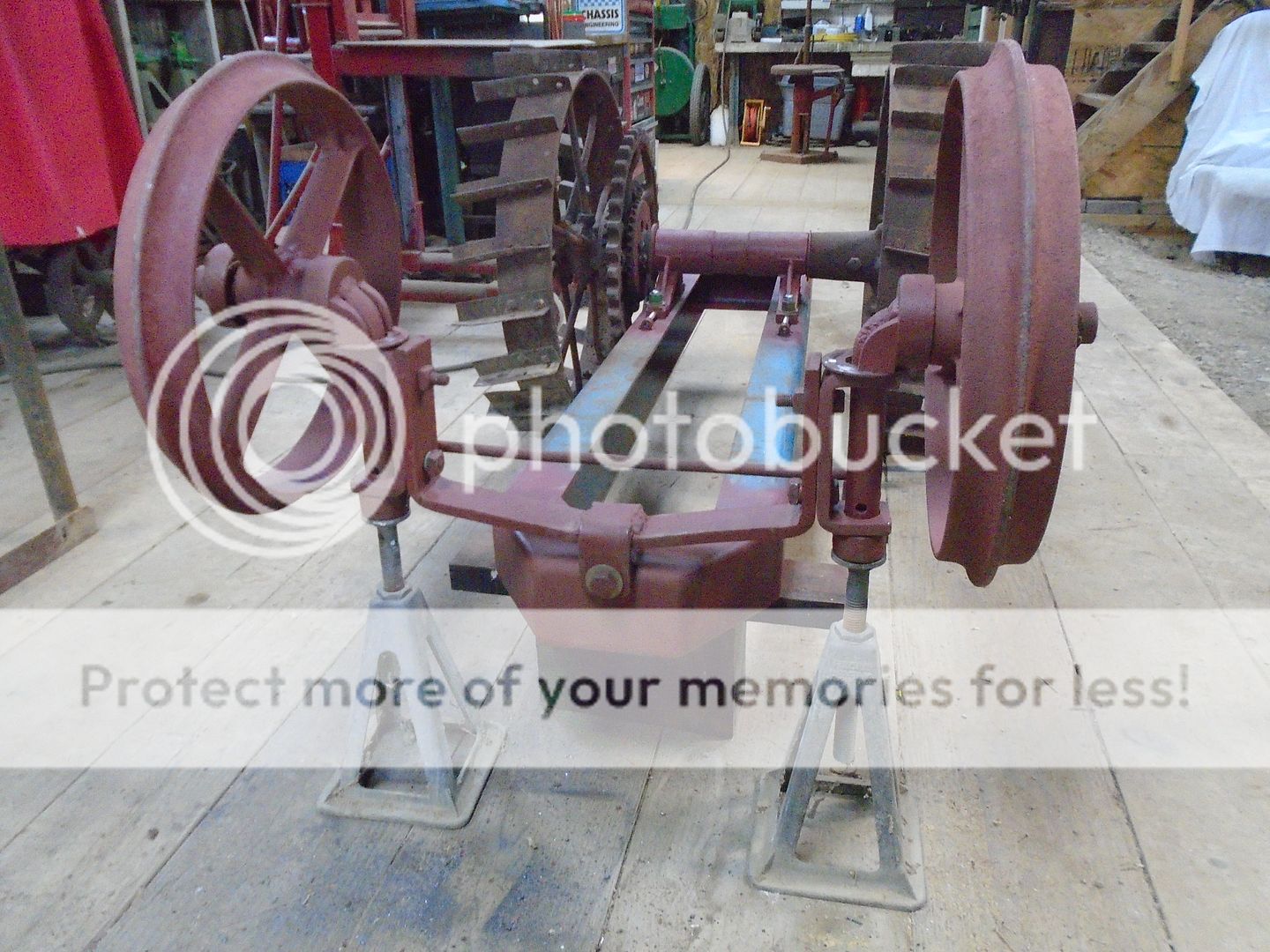
To make it easier to put these radius rods on, I picked the front of the frame up and turned it over.
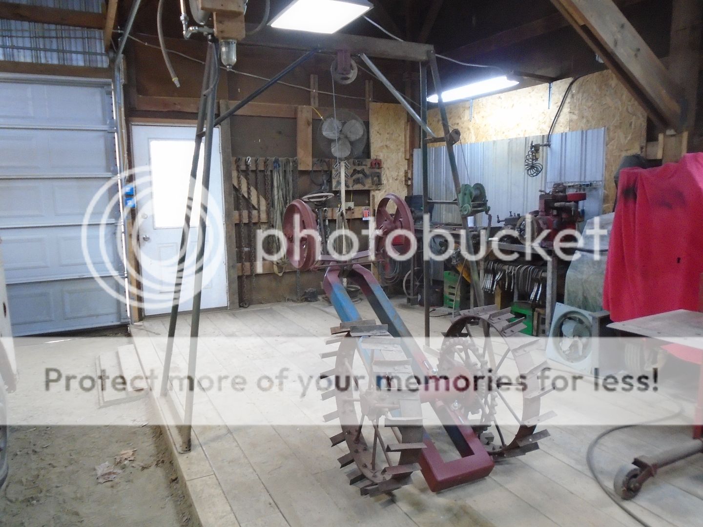
With the frame now upside down, I put a pair of screw jacks under the axle to keep it from rocking from side to side.
Whoever originally converted this walk behind tractor to a riding tractor had the radius rods mounted on the two longer bolts with the nuts tightened down on them.
This did not allow the front of the radius rods to pivot.
With them being bent like they were, I'm guessing there was enough flexing in the rods that it didn't matter that much if the front ends were fastened down tight.
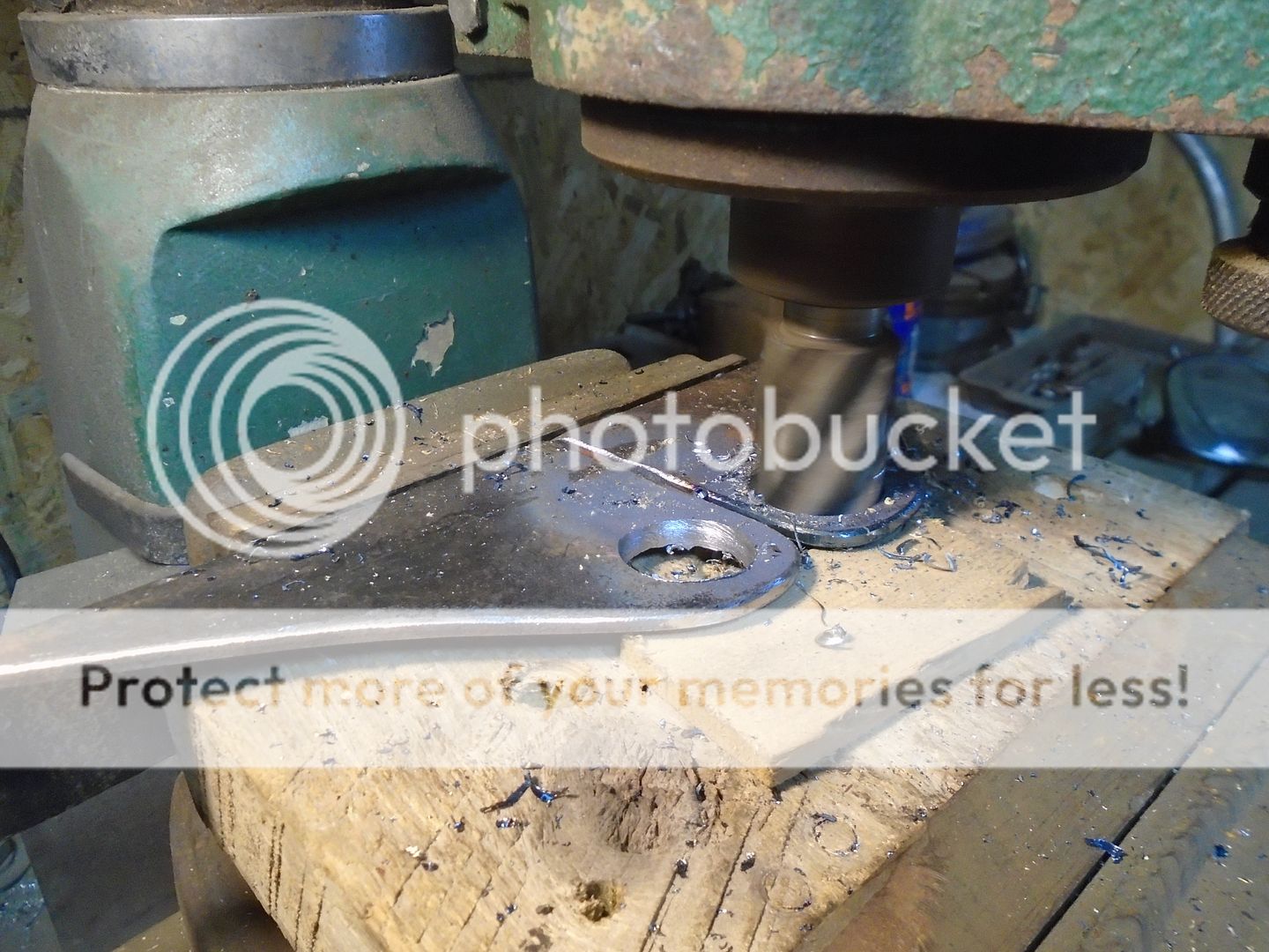
To correct that problem, I drilled the mounting hole in the front of the radius rods to a larger size.
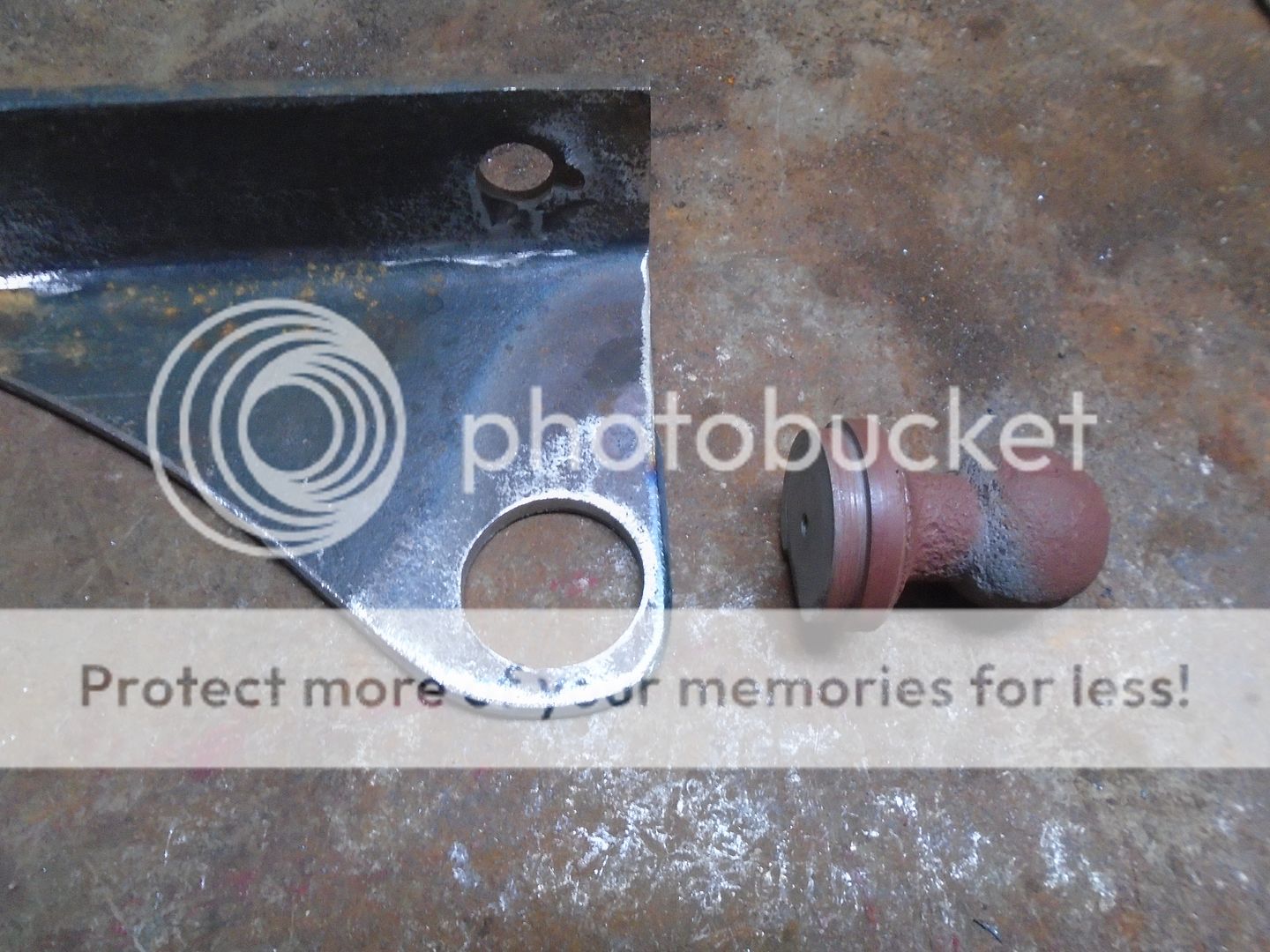
Then I got longer nuts and machined a boss on them.
The front end of the radius rods can now pivot on the nuts with the nuts fastened down tight to the axle.
The other end of the radius rods have an Ford Model - A, adjustable ball and socket style tie rod end.
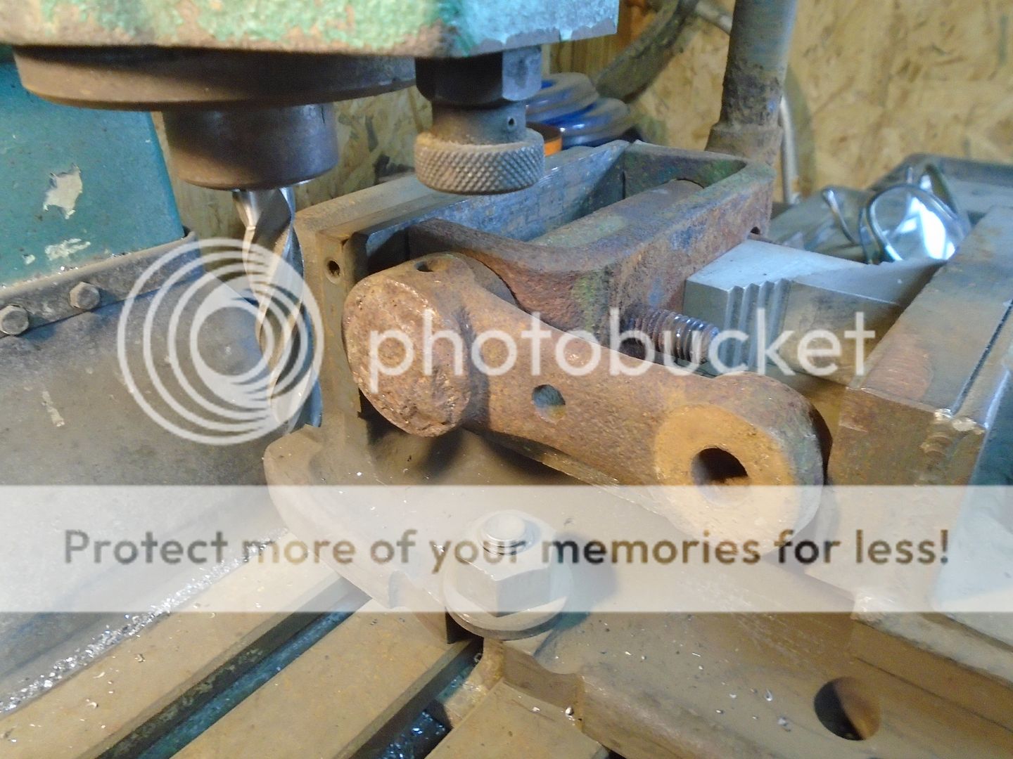
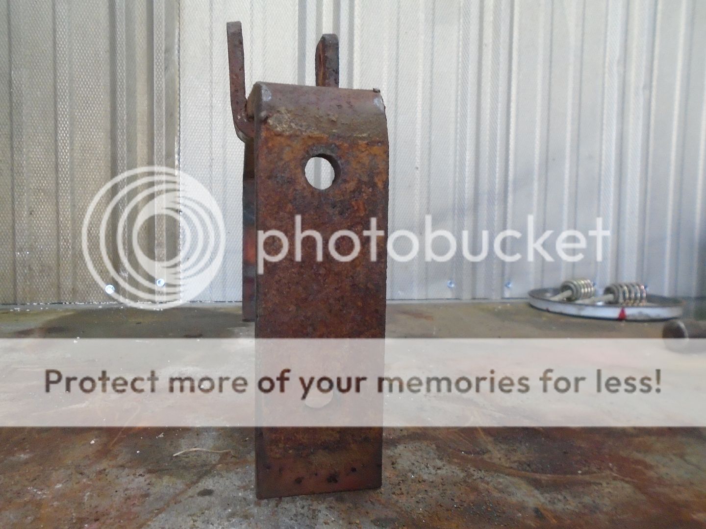
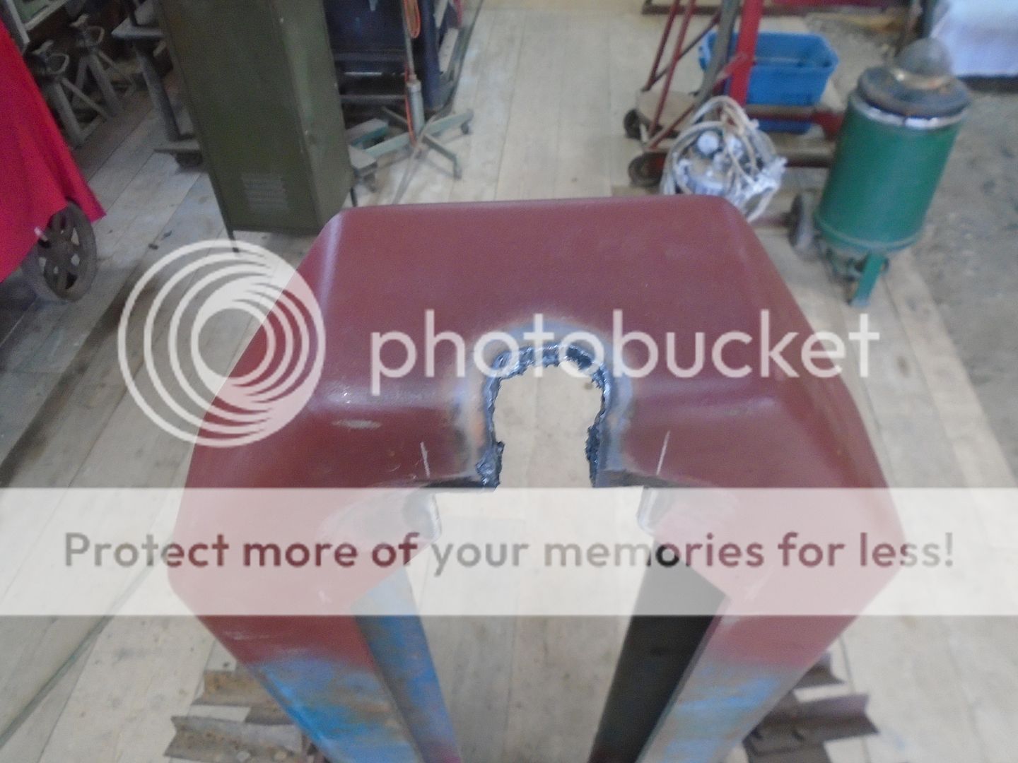
In my junk I found a pair of angle mounts off something that will work well to mounting the back end of these radius rods.
I put them up in the mill and bored a 1-1/8 inch hole in them.
I had already turned the back of the tie rod balls to a 1-1/8 inch diameter.
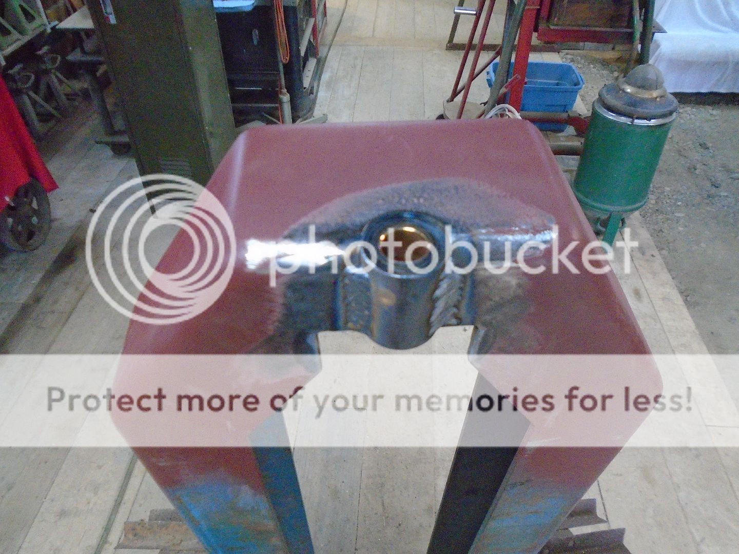
The tie rod ball is fit into the hole in the bracket and clamped in the vice.
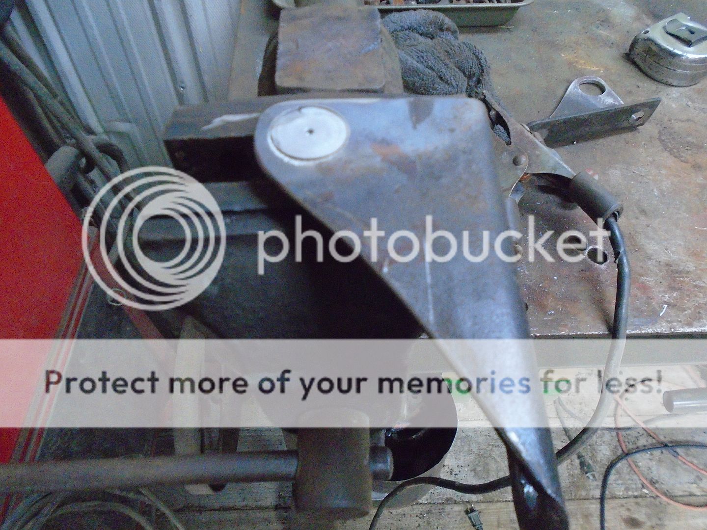
Then it is welded in place.
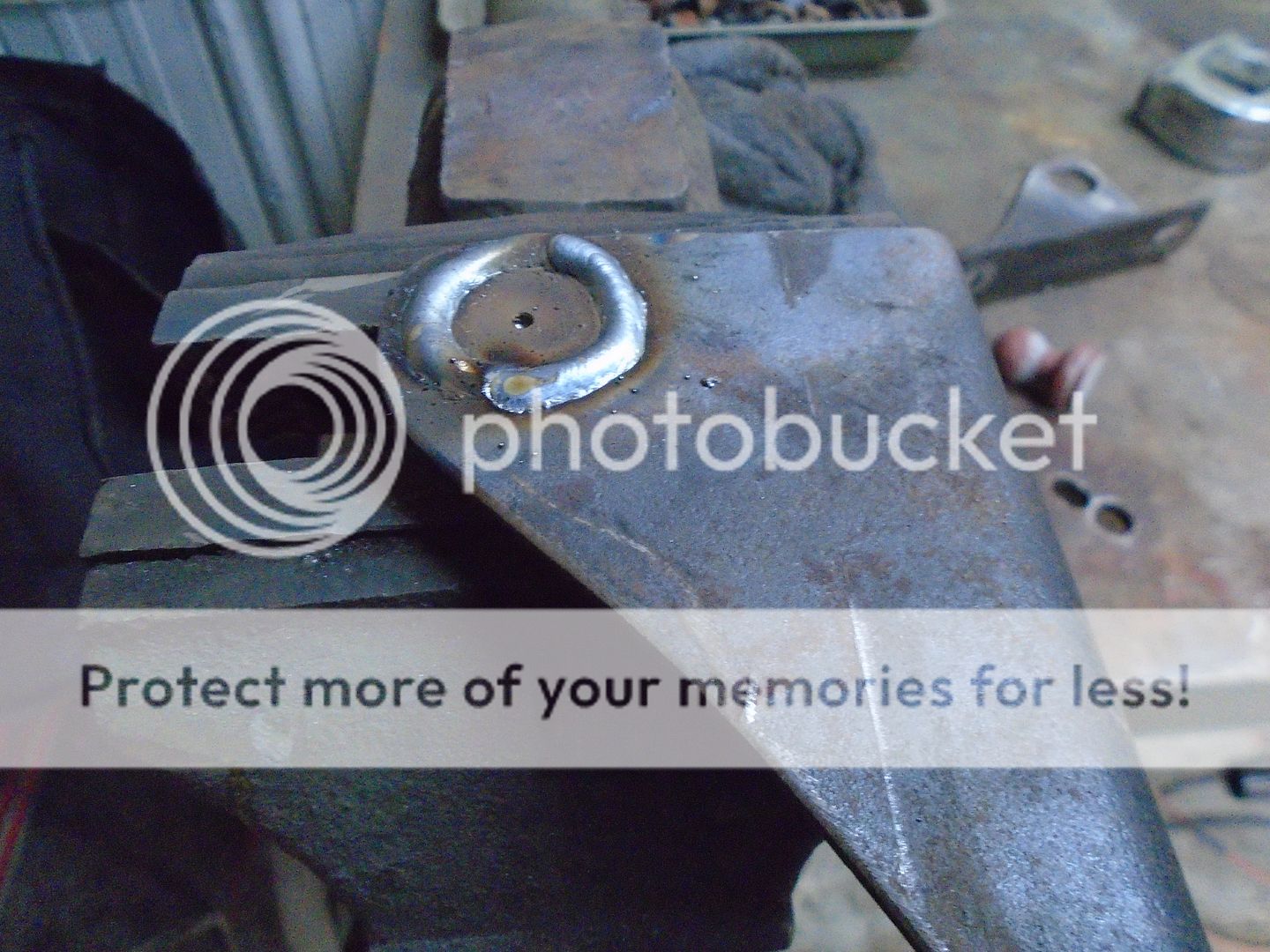
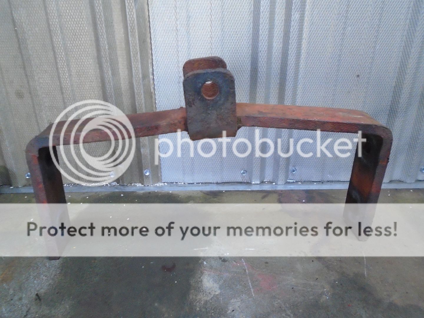
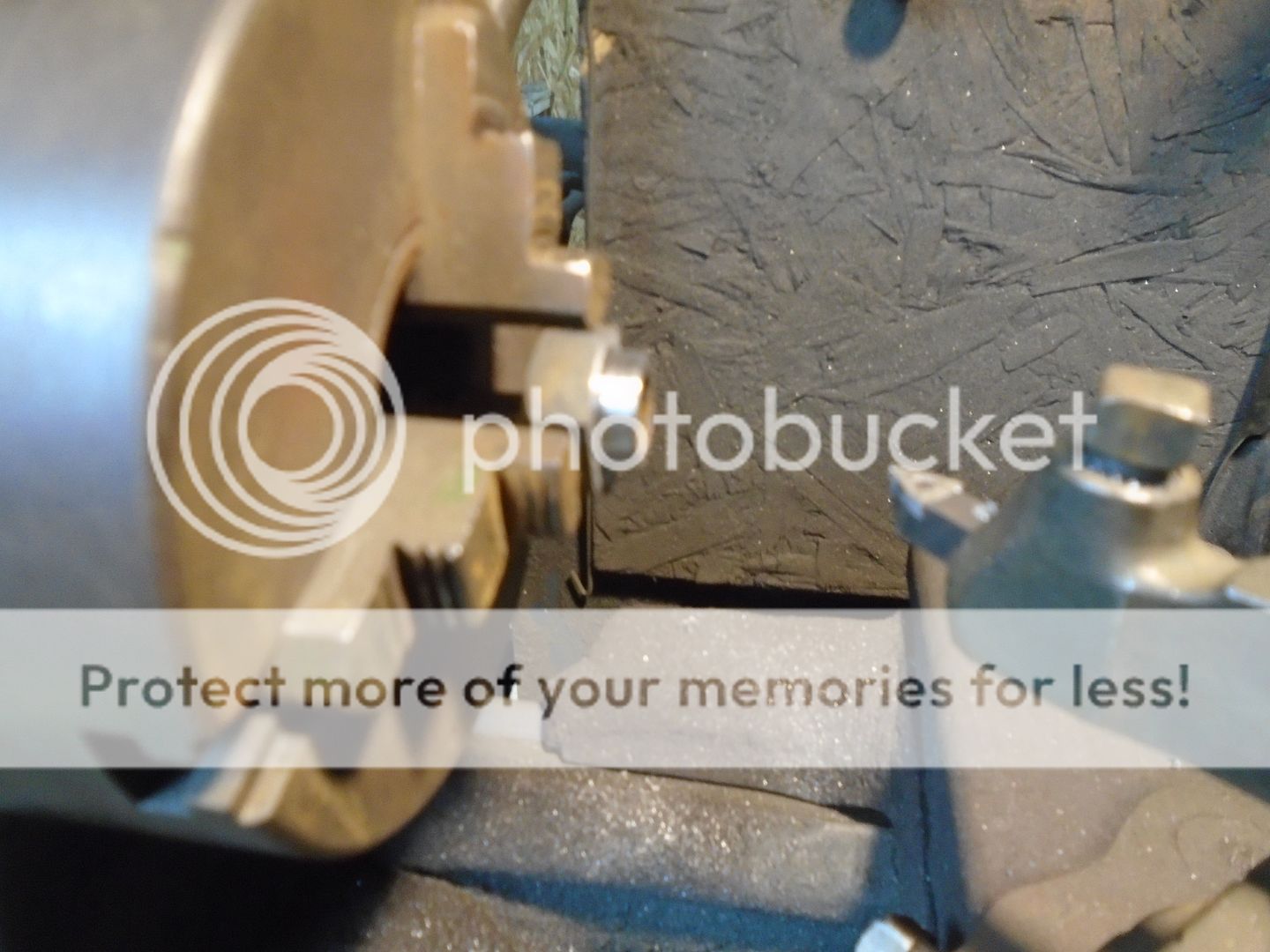
Here is how the brackets look from the front side.
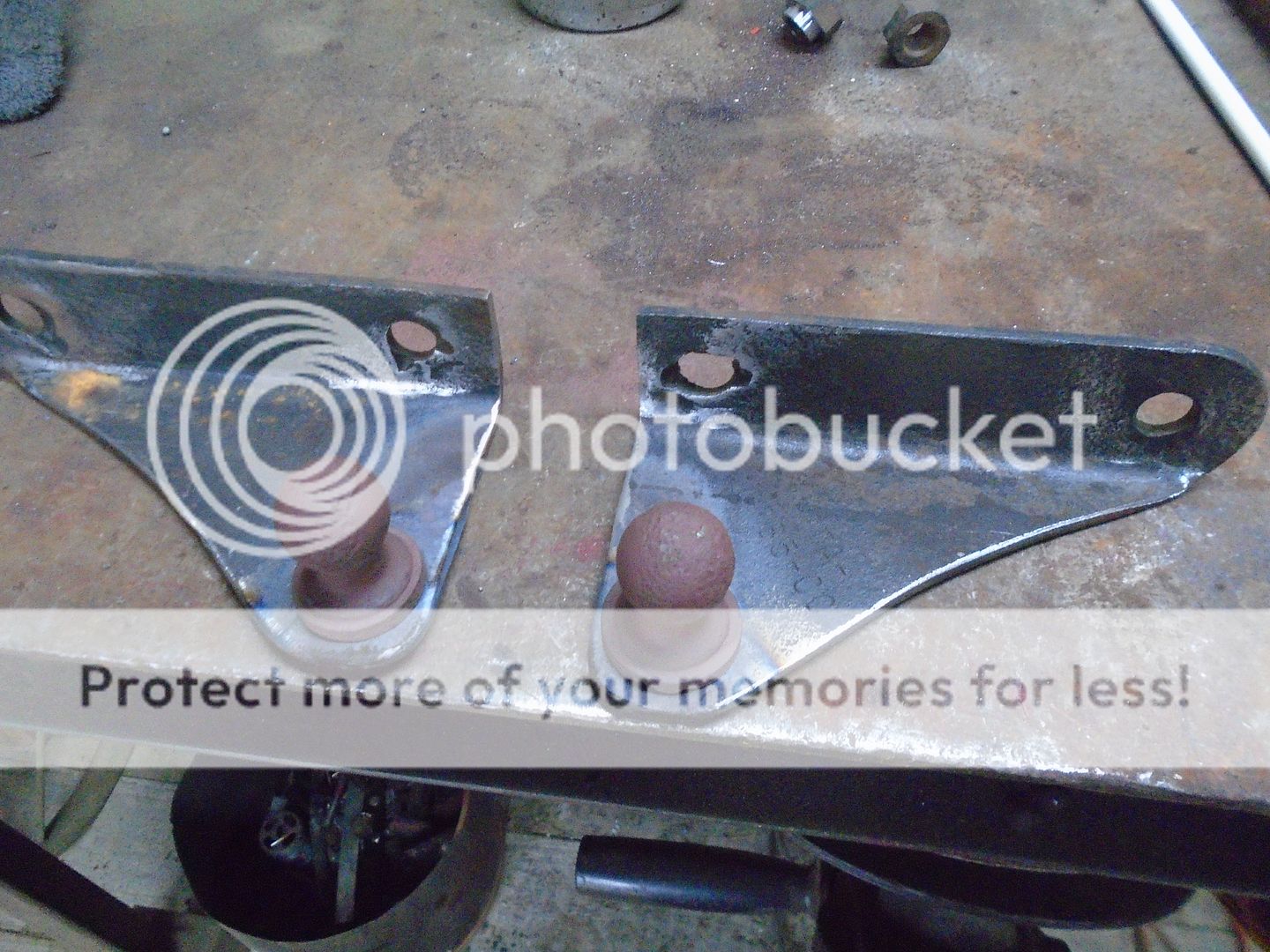
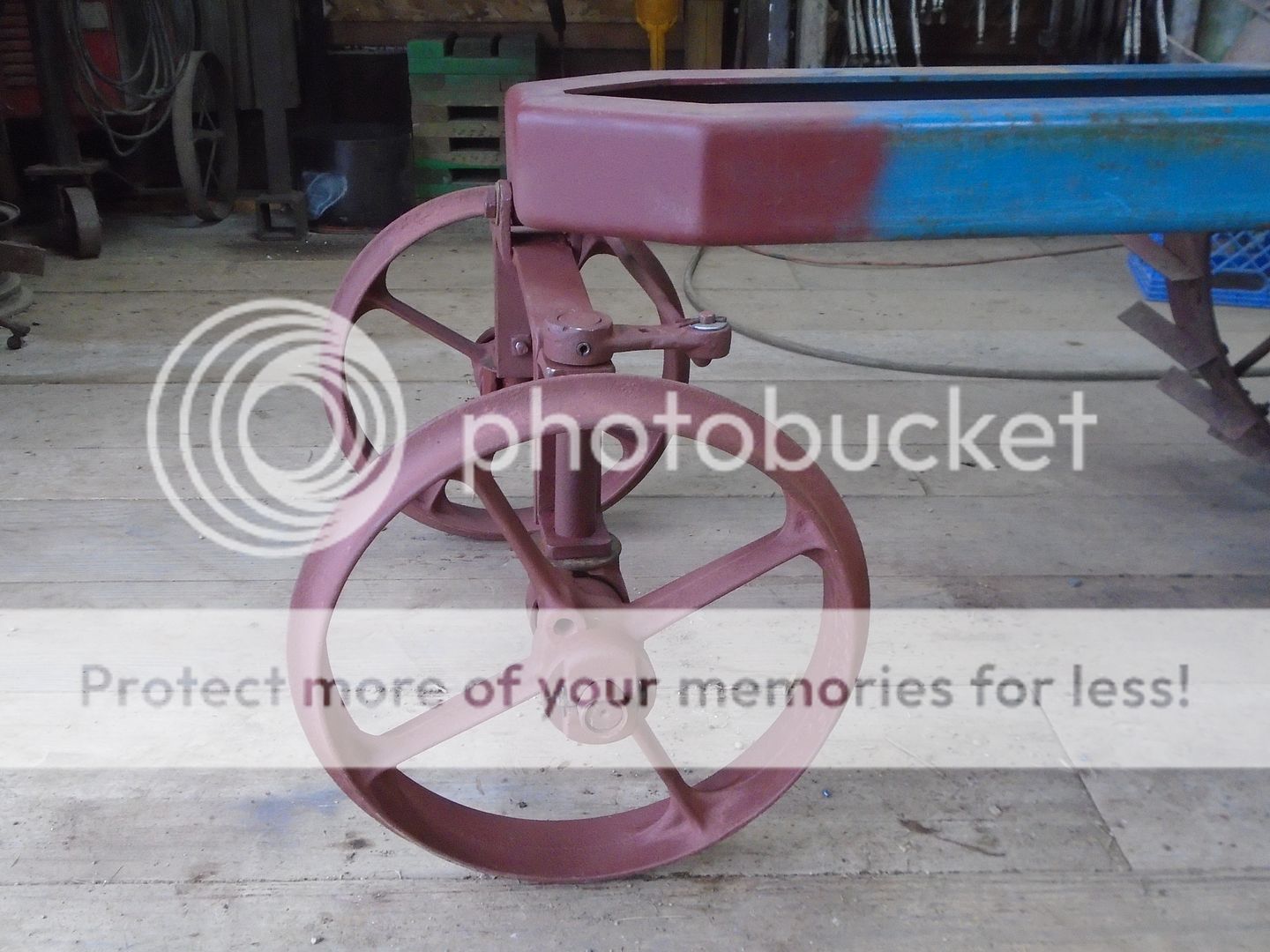
The radius rods are fastened to the front axle and the rear mounting brackets are welded to the underside of the frame.
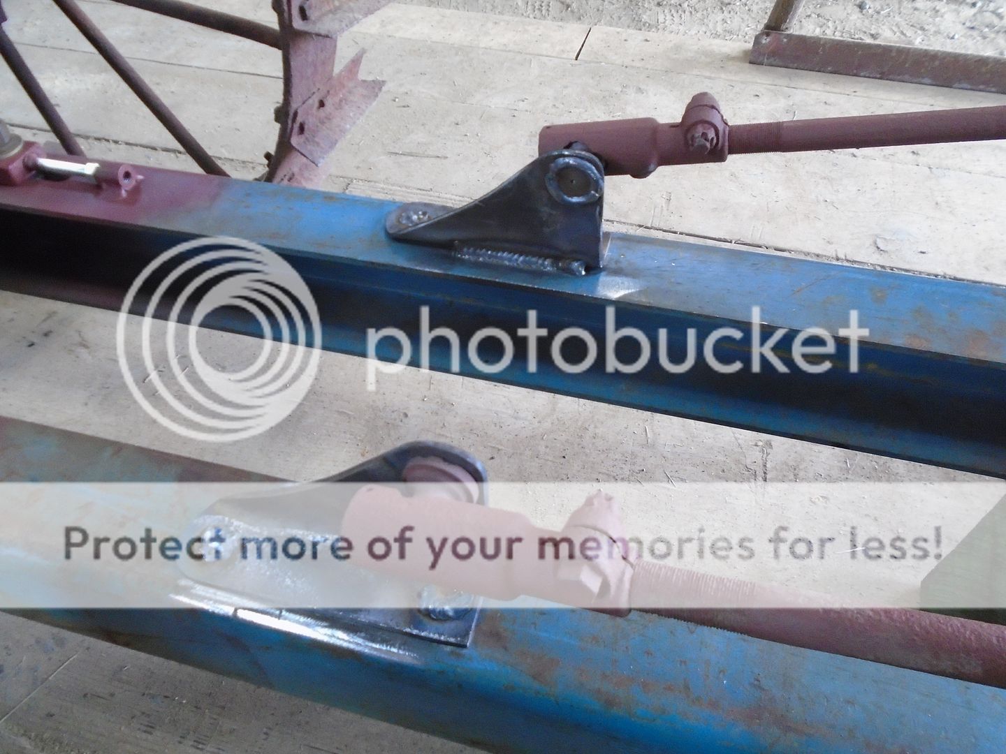
The frame is then picked back up and turned back over on its wheels.


The front of the frame is then cut out.

And the pivot mount is welded in place.

The wheels were mounted on the spindles and the axle assembly is mounted to the frame.
... Note ... the two lower bolts holding holding the spindle mounts to the axle bar are longer then the two upper bolts.
The radius rods will fasted to these longer bolts.


These are the radius rods that keep the front axle from moving backward or forward.
Obviously, they need a little work.

They were straightened by pressing them in between two flat steel bars.
I kept rotating them around as I operated the press until they were straight.

Then they were sand blasted and primed.

To make it easier to put these radius rods on, I picked the front of the frame up and turned it over.

With the frame now upside down, I put a pair of screw jacks under the axle to keep it from rocking from side to side.

Whoever originally converted this walk behind tractor to a riding tractor had the radius rods mounted on the two longer bolts with the nuts tightened down on them.
This did not allow the front of the radius rods to pivot.
With them being bent like they were, I'm guessing there was enough flexing in the rods that it didn't matter that much if the front ends were fastened down tight.
To correct that problem, I drilled the mounting hole in the front of the radius rods to a larger size.
Then I got longer nuts and machined a boss on them.

The front end of the radius rods can now pivot on the nuts with the nuts fastened down tight to the axle.

The other end of the radius rods have an Ford Model - A, adjustable ball and socket style tie rod end.
In my junk I found a pair of angle mounts off something that will work well to mounting the back end of these radius rods.
I put them up in the mill and bored a 1-1/8 inch hole in them.

I had already turned the back of the tie rod balls to a 1-1/8 inch diameter.

The tie rod ball is fit into the hole in the bracket and clamped in the vice.

Then it is welded in place.

Here is how the brackets look from the front side.

The radius rods are fastened to the front axle and the rear mounting brackets are welded to the underside of the frame.

The frame is then picked back up and turned back over on its wheels.


Did you consider converting the spindle mounts to a bushing with a grease zerk?
No ..
The original two wheel garden tractor was built somewhere between 1923 and 1925.
I figure that this was most likely converted into a riding tractor in the late 20's or early 30's because of the square head bolts and nuts that were used and, within reason, I'm trying keep the engineering the same as it was built.
With this only being used for displaying at tractor shows, I'm not worried about the spindles wearing out even without grease fittings.
I did however, grease the wheel hubs before I assembled them.
It got up into the 50's today so I was able to spend some time out in the garage working on the tractor.
The driveshaft is made up and slipped in into the flywheel and I bolted the clutch and pressure plate on.
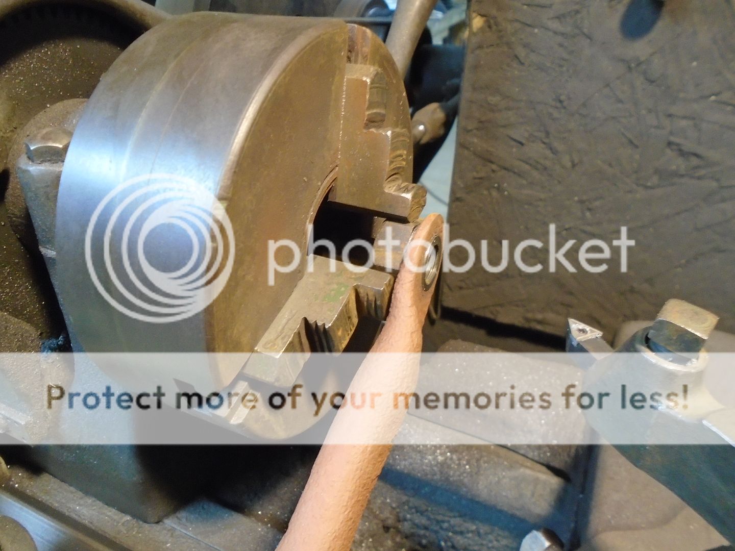
I made a bushing out of wood for the center hole in the throw out bearing.
Then I put the throw out bearing in place with the wood bushing keeping it centered on the drive shaft.
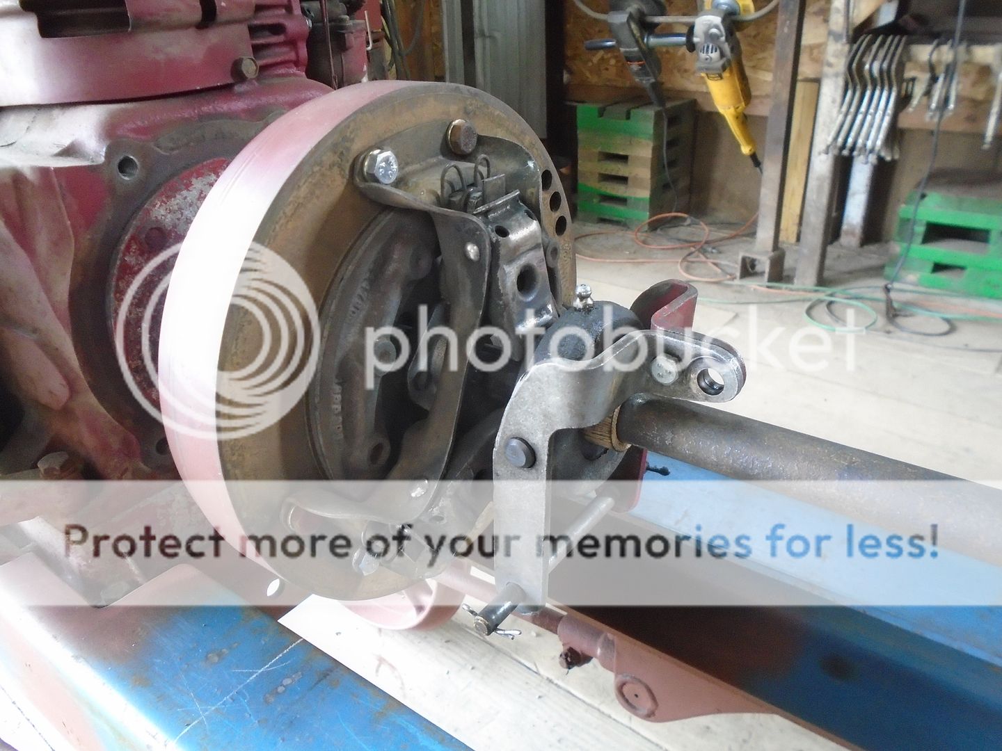
The other end of the drive shaft is connected to the coupling on the transmission.
I also have a pillow block bearing mounted on this end of the drive shaft.
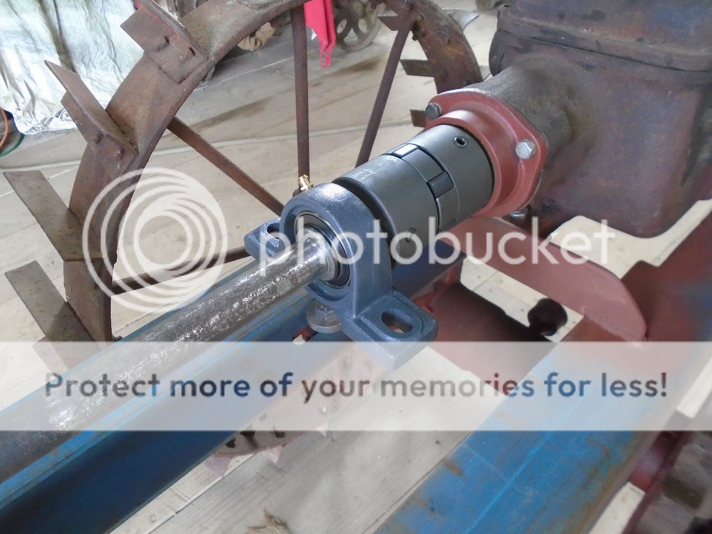
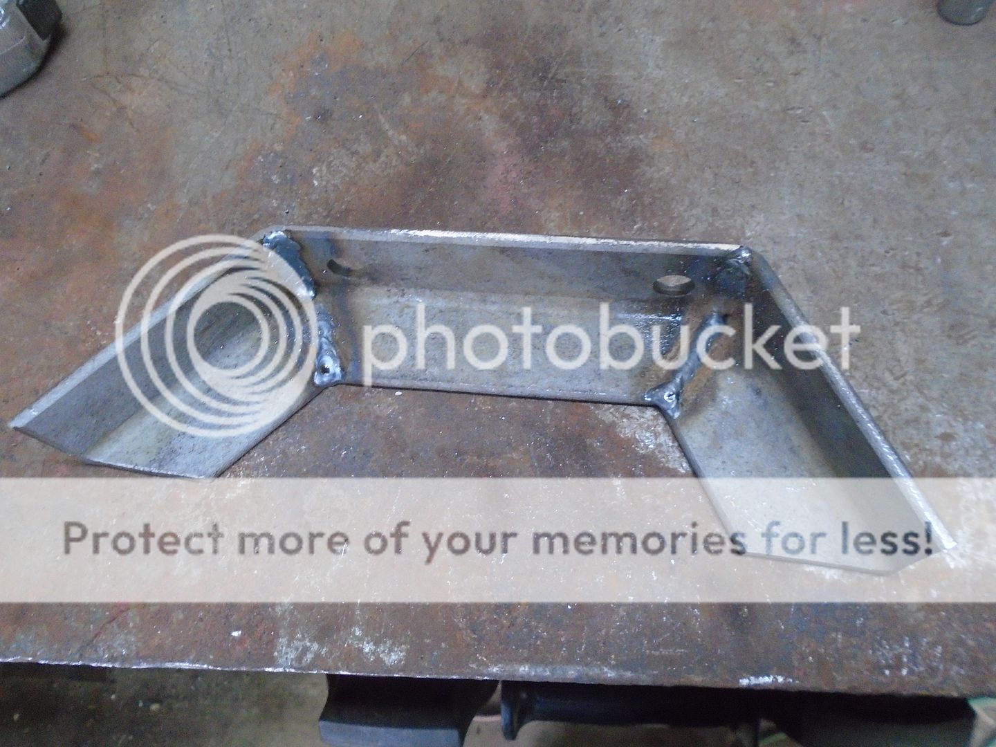
I made up a bracket out of angle iron to go under the pillow block bearing.
Here's how it looks with the bracket welded to the frame and the pillow block bearing bolted to it.
The driveshaft is made up and slipped in into the flywheel and I bolted the clutch and pressure plate on.
I made a bushing out of wood for the center hole in the throw out bearing.
Then I put the throw out bearing in place with the wood bushing keeping it centered on the drive shaft.

The other end of the drive shaft is connected to the coupling on the transmission.
I also have a pillow block bearing mounted on this end of the drive shaft.

I made up a bracket out of angle iron to go under the pillow block bearing.

Here's how it looks with the bracket welded to the frame and the pillow block bearing bolted to it.

That driveshaft looks big compared to the ones on a GT. Your coming along nicely.
The drive shaft is off the Farmall Cub that I got the clutch and flywheel from.
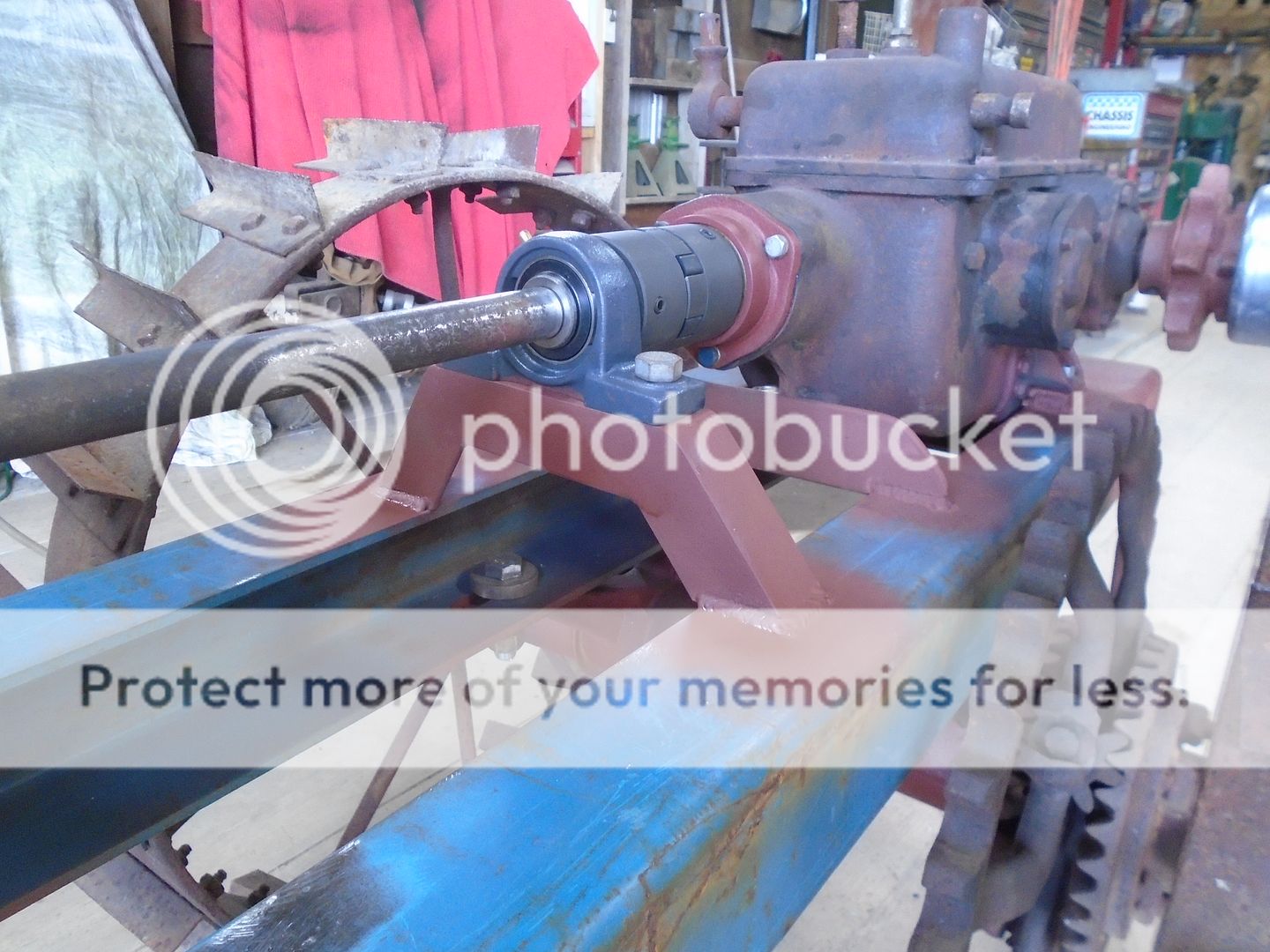
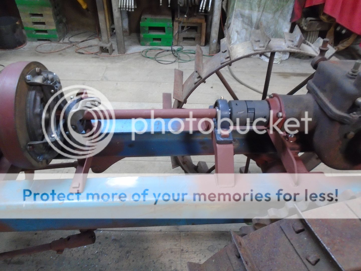
The drive shaft is finished and assembled on the tractor.
Earlier I had stated that I thought that whoever had converted this two wheel walk behind tractor to a four wheel riding tractor, may have done it back in the late 20's or early 30's because of the extensive use of square head bolts and nuts that were used to put it together.
To maintaing the original look of the tractor, I am also using square head bolts and nuts to mount the transmission, pillow block bearing and the mounting bracket for the throw out bearing.
This is the bracket that I made up for mounting the throw out bearing.
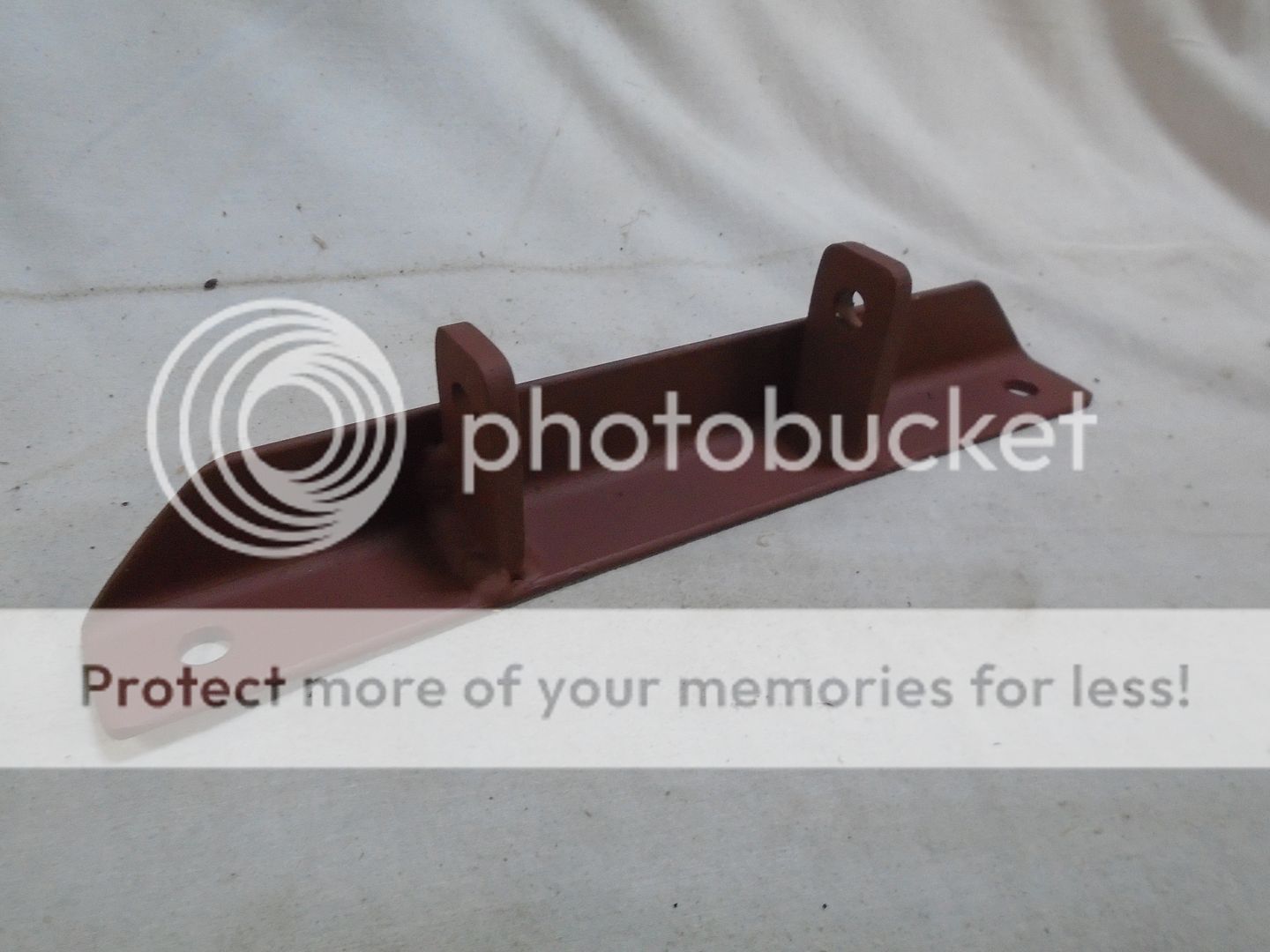
The mounting bracket for the pillow block bearing was welded to the frame.
This mounting bracket for the throw out bearing is bolted to the frame instead of being welded because it will be a lot easier to work on the clutch or remove the flywheel if I can get this bracket out of the way.
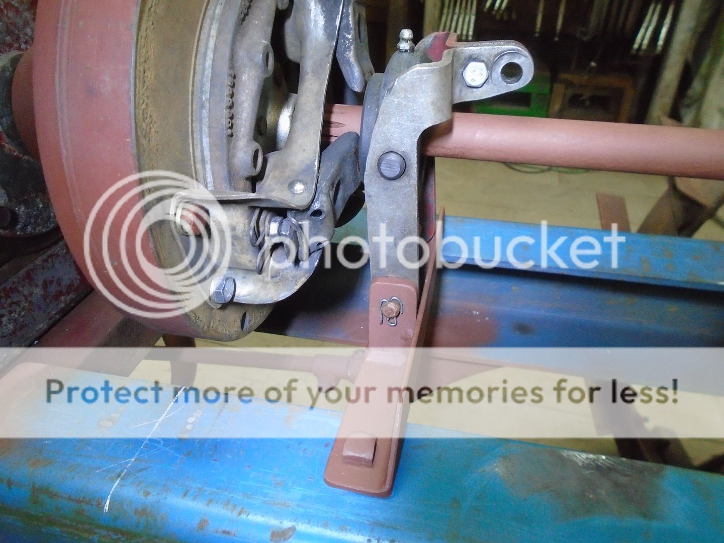
As you can see, the hole in the throw out bearing is a lot bigger then the diameter of the drive shaft.
This is why I had made up a wood bushing to keep the throw out bearing centered on the drive shaft while I made the mounting bracket for it.
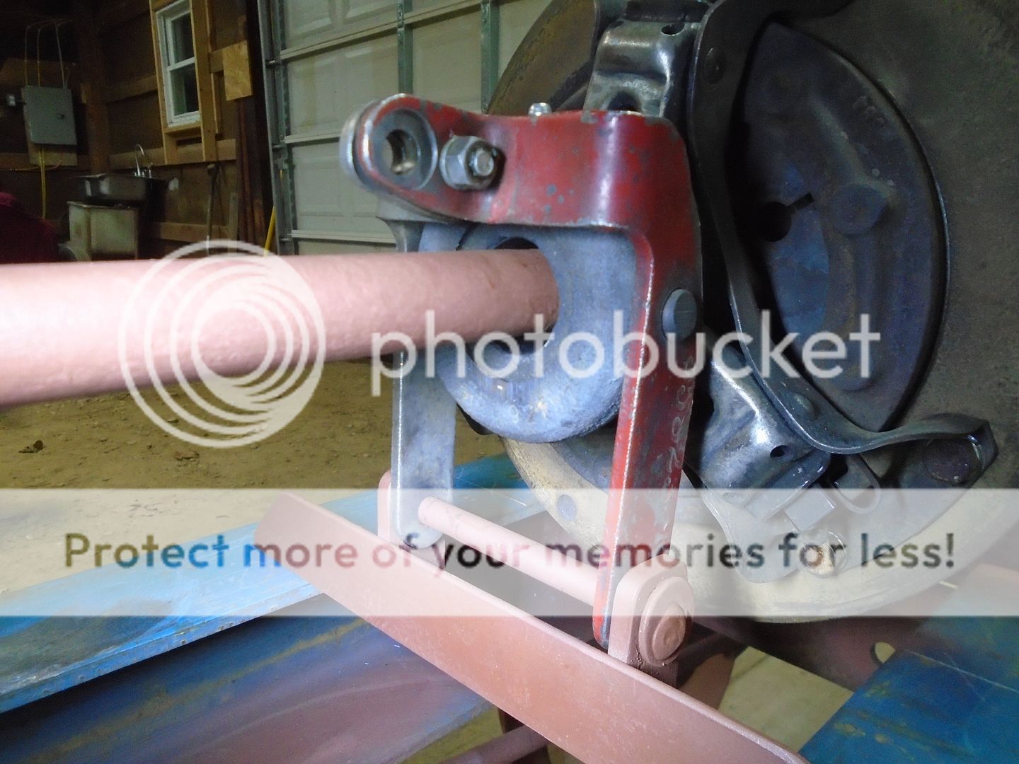
The wood bushing was removed from the throw out bearing before it was fastened in place.
This is the wood bushing.

Earlier I had stated that I thought that whoever had converted this two wheel walk behind tractor to a four wheel riding tractor, may have done it back in the late 20's or early 30's because of the extensive use of square head bolts and nuts that were used to put it together.
To maintaing the original look of the tractor, I am also using square head bolts and nuts to mount the transmission, pillow block bearing and the mounting bracket for the throw out bearing.

This is the bracket that I made up for mounting the throw out bearing.

The mounting bracket for the pillow block bearing was welded to the frame.
This mounting bracket for the throw out bearing is bolted to the frame instead of being welded because it will be a lot easier to work on the clutch or remove the flywheel if I can get this bracket out of the way.

As you can see, the hole in the throw out bearing is a lot bigger then the diameter of the drive shaft.
This is why I had made up a wood bushing to keep the throw out bearing centered on the drive shaft while I made the mounting bracket for it.

The wood bushing was removed from the throw out bearing before it was fastened in place.
This is the wood bushing.
