Winter project

The temperature got up into the 50's today so I spent some time working out in the garage.

I'm going to use the common ' U ' shape seat spring from an older garden tractor and I want to mount the spring right on top of the transmission.
I don't want to rely on holes just threaded into the 1/4 inch thickness of the 95 year old cast iron of this transmission so I need to put a piece of flat steel on the inside that I can thread the spring mounting bolts into.

I'm going to use a piece of 3/8 thick flat steel plate for the extra support and I need to fasten it to the inside of the transmission cover.
First I marked and drilled a small hole for where the front spring bolt will go and from that, I can figure out where to drill the countersunk holes for the flathead screws.


The holes are drilled deep enough so the tops of the screws are a little below the surface of the transmission cover.


Then I drilled and threaded the holes in the piece of flat steel.


The steel plate is now fastened to the inside of the transmission cover with two countersunk screws.


The holes for mounting the spring are drilled into the transmission cover and the threads are tapped thru the cast iron and the 3/8 inch steel plate.


The spring is bolted onto the top of the transmission and the seat is mounted in place.
With the steel plate fastened to the inside of the transmission, I can remove the seat spring and re-attach it without having to take the transmission cover off.


Bending up a battery box out of 1/8 inch sheet steel.


This is the finished box.


It is primed and mounted in between the frame rails.


The top of the battery [post set about 1/2 inch below the top of the frame rails.


The battery box hangs down under the frame.


The battery will be covered by this removable section of foot plate.

 
I drilled holes into a section of angle iron and then clamped it to the underside of the foot plate.


The angle iron is welded in place to strengthen the outer edge.


Mounting holes were drilled thru the foot plate and corresponding holes were drilled and tapped into the frame.
Then the foot plate was cut into three sections.


Additional angle iron and bracing rods are welded to the two outside sections.


The two outer sections are then welded to the frame rails.


And the bracing rods are welded in place.


The center section is fastened in place with six machine screws to complete the foot plate and leave easy access to the battery underneath it.

 
I know you have something in mind..... but for now I just keep thinking " Make sure your shoe laces are tied"
Very nice job, you do amazing metal work!
 
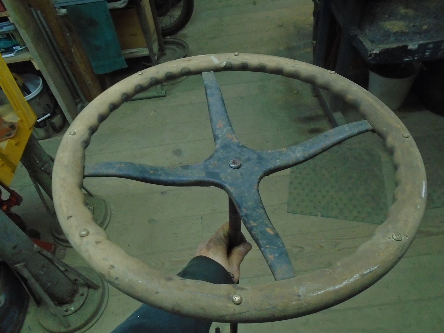
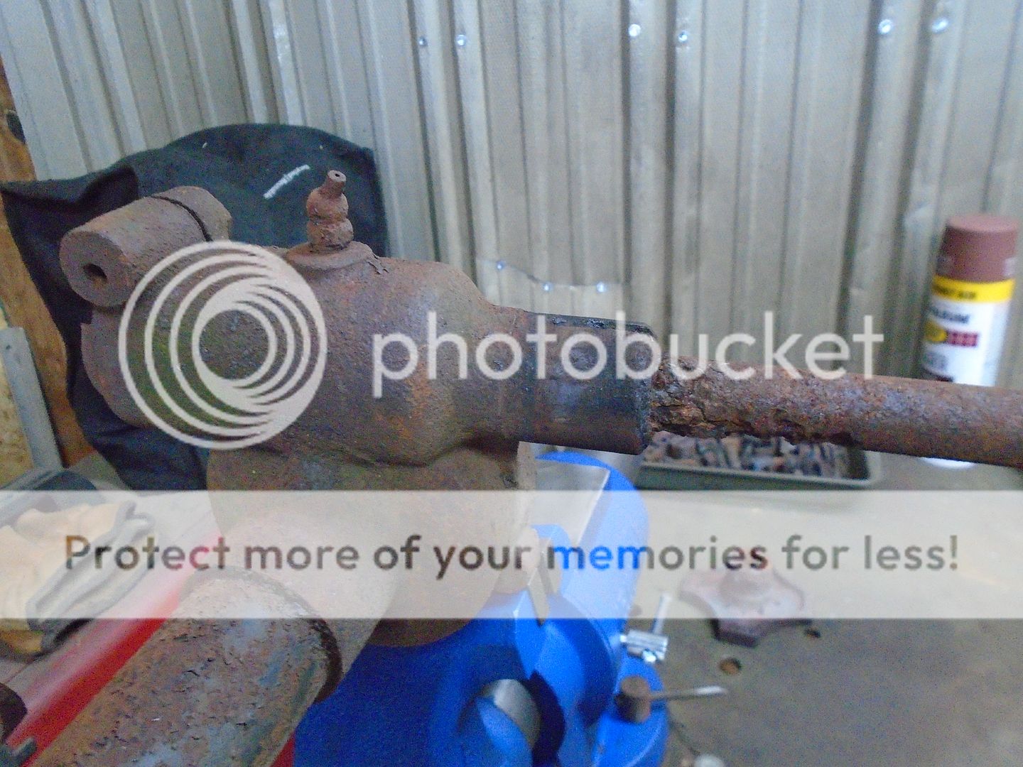
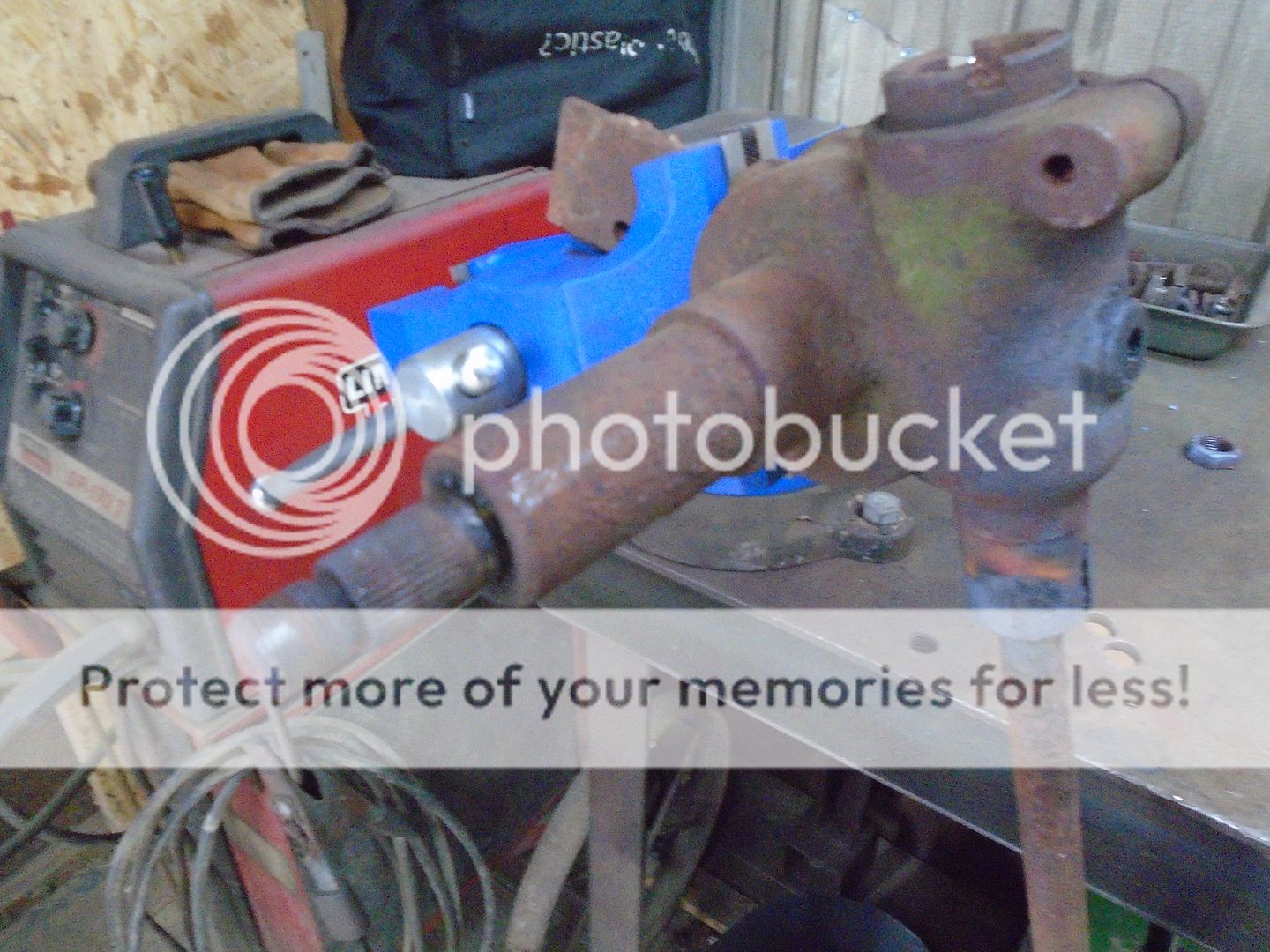
In these photos, you can see the steering column that came with this tractor.


At some point, a more modern steering wheel had been mounted to it.
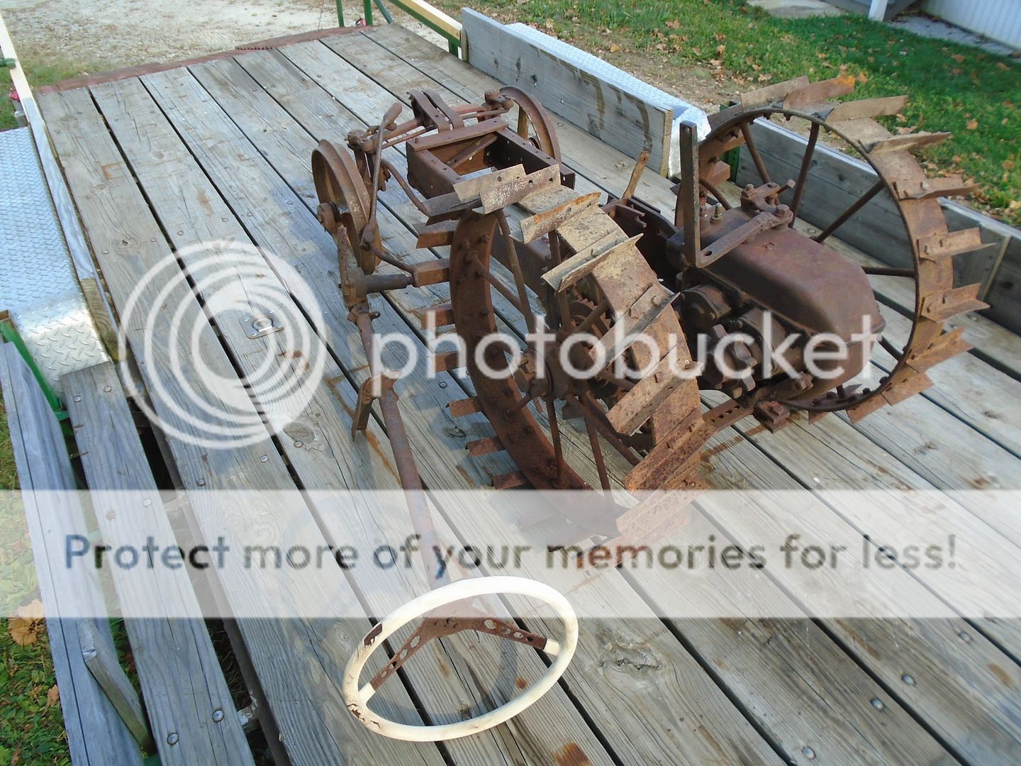
I removed that steering wheel and then used a puller to remove what was left of the original steering wheel.


Then I was able to remove the steel tube of the column from the steering box.


Here are the parts of the column tube.
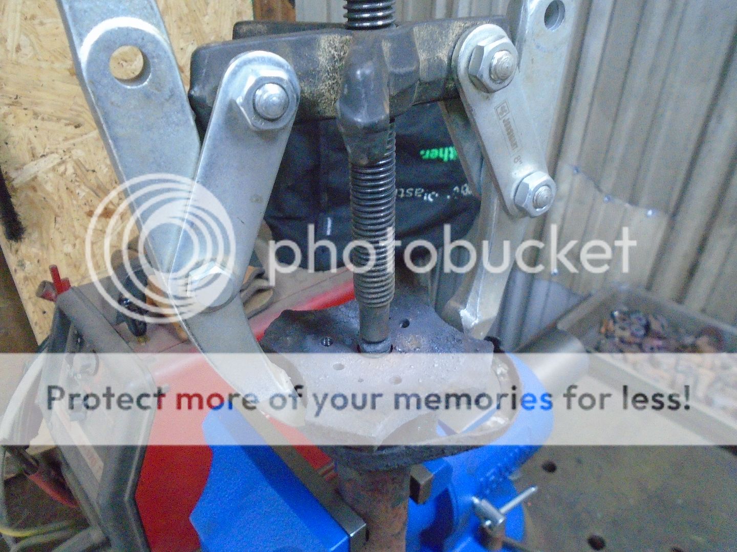
This is not Ford a model-T steering column but it had the same type of control levers like the Ford did.


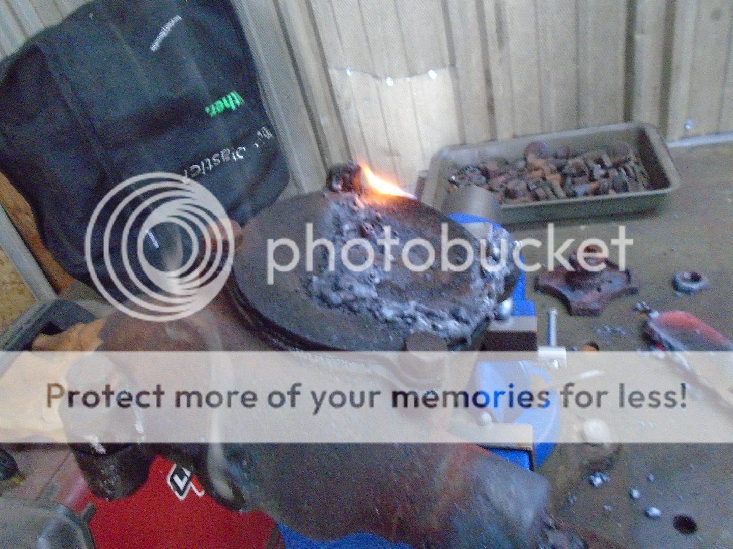
Over the years, water has run down inside the column tube and rusted the steering shaft tight to the steering box.


By heating up the steering box, I was able to knock the rust out between the box and the shaft.


That was all that was keeping the steering shaft from moving and it moves freely now.


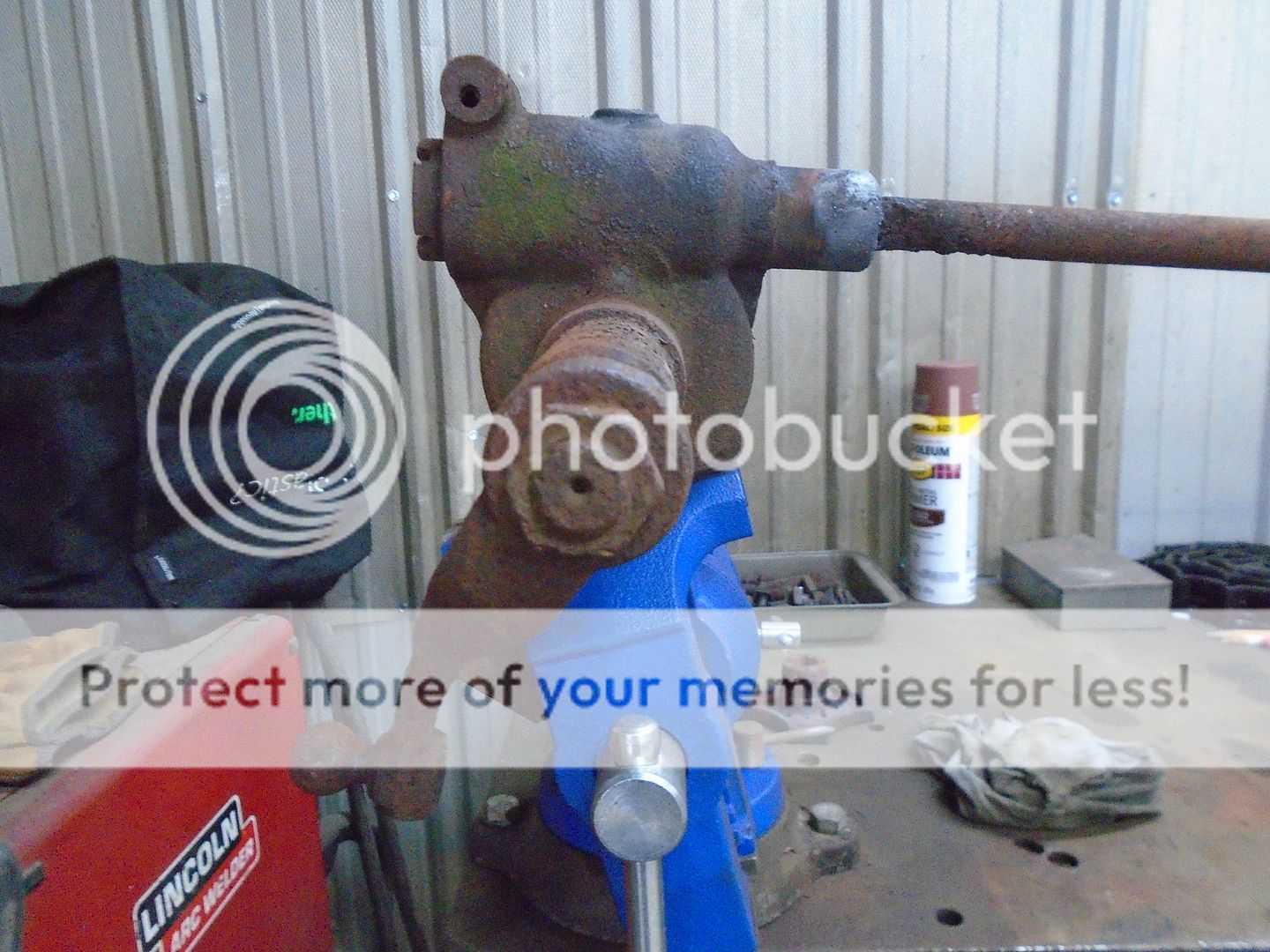
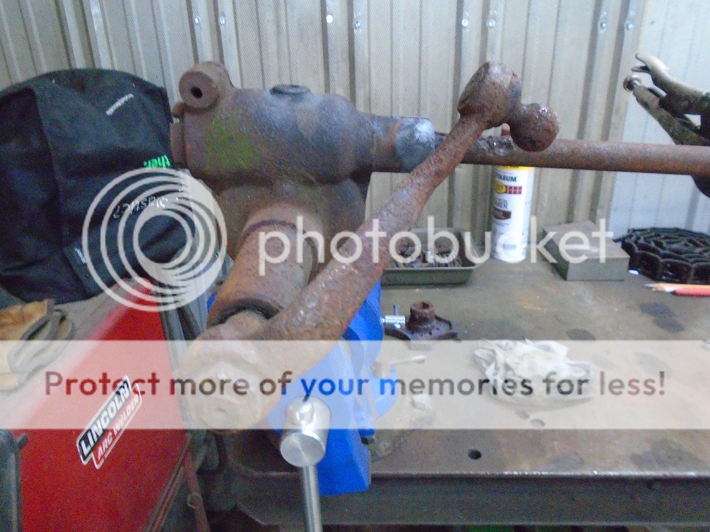
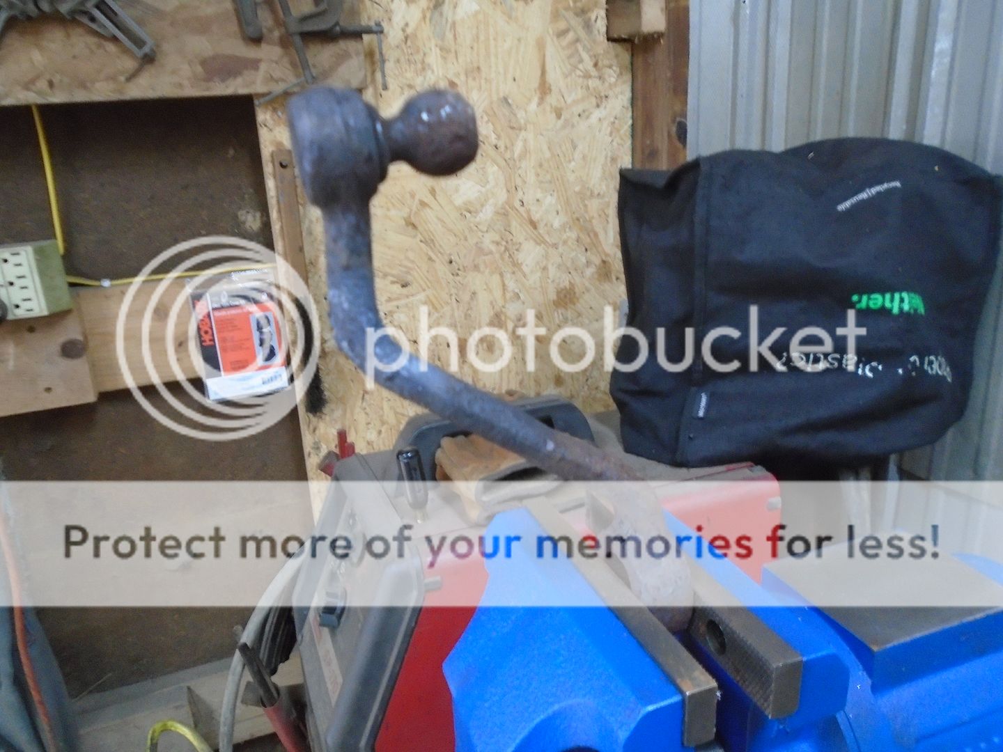
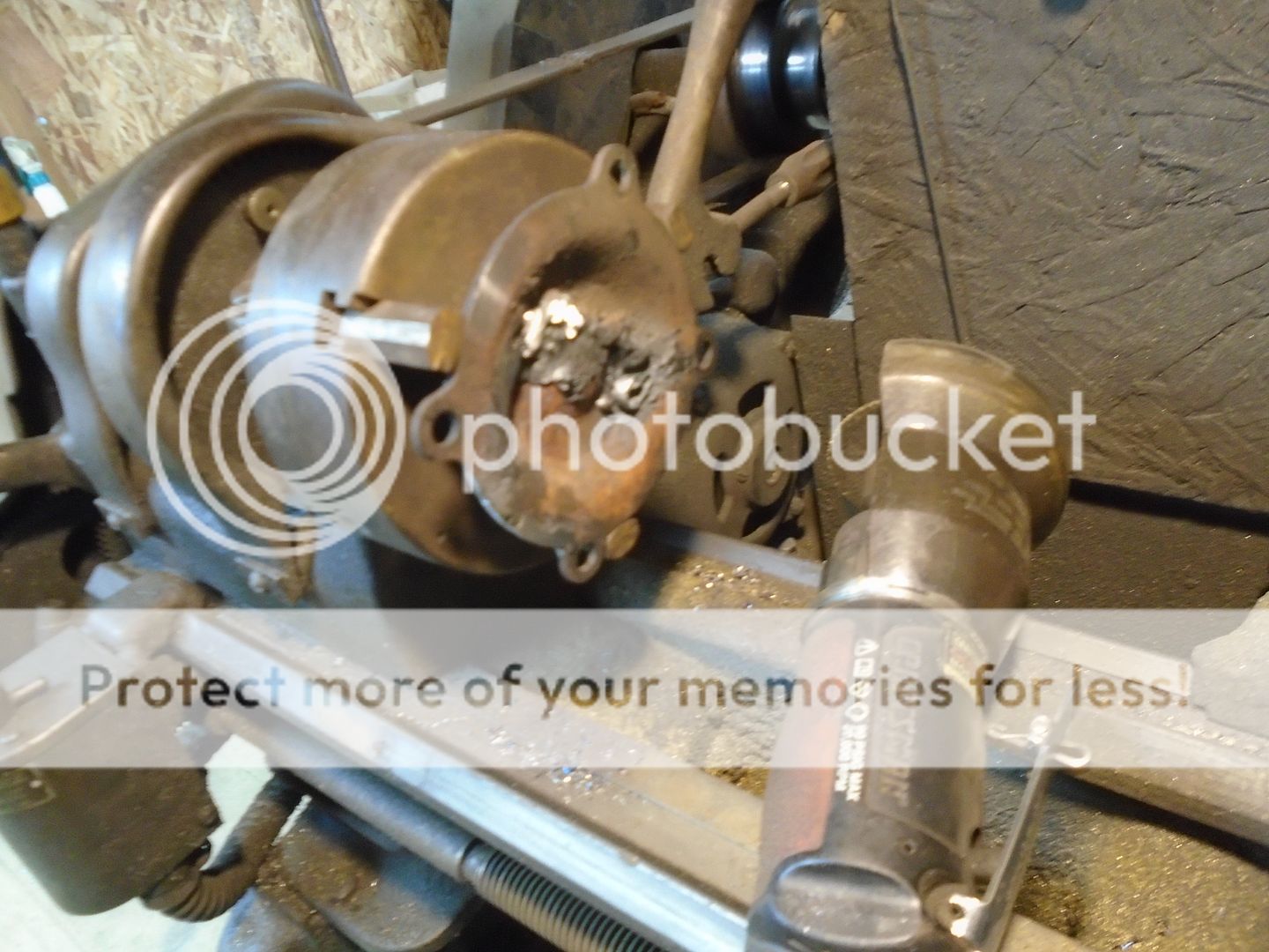
As you can see, the ball mount for the drag link is twisted around 90 degrees to the steering box.
I was able to remove the steering arm without having to use heat on it.


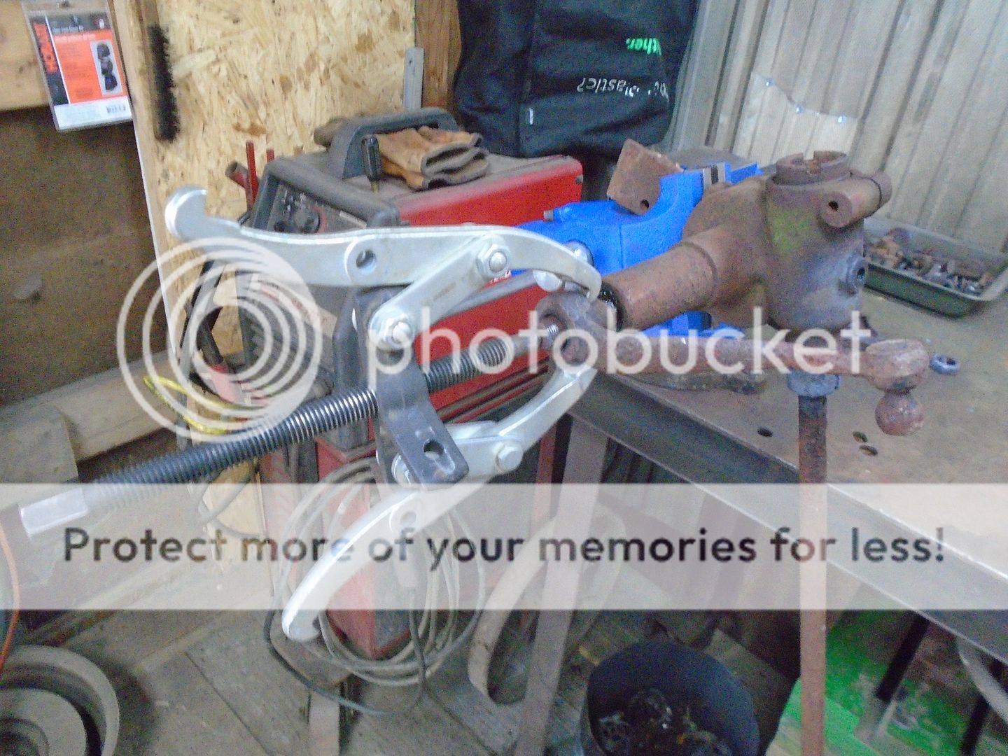
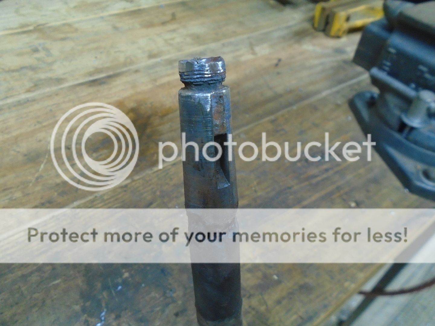
The splines and threads are all still in good condition on the steering shaft.


I heated up the end of the arm and twisted the ball back around so it is now inline with the shaft coming out of the steering box.


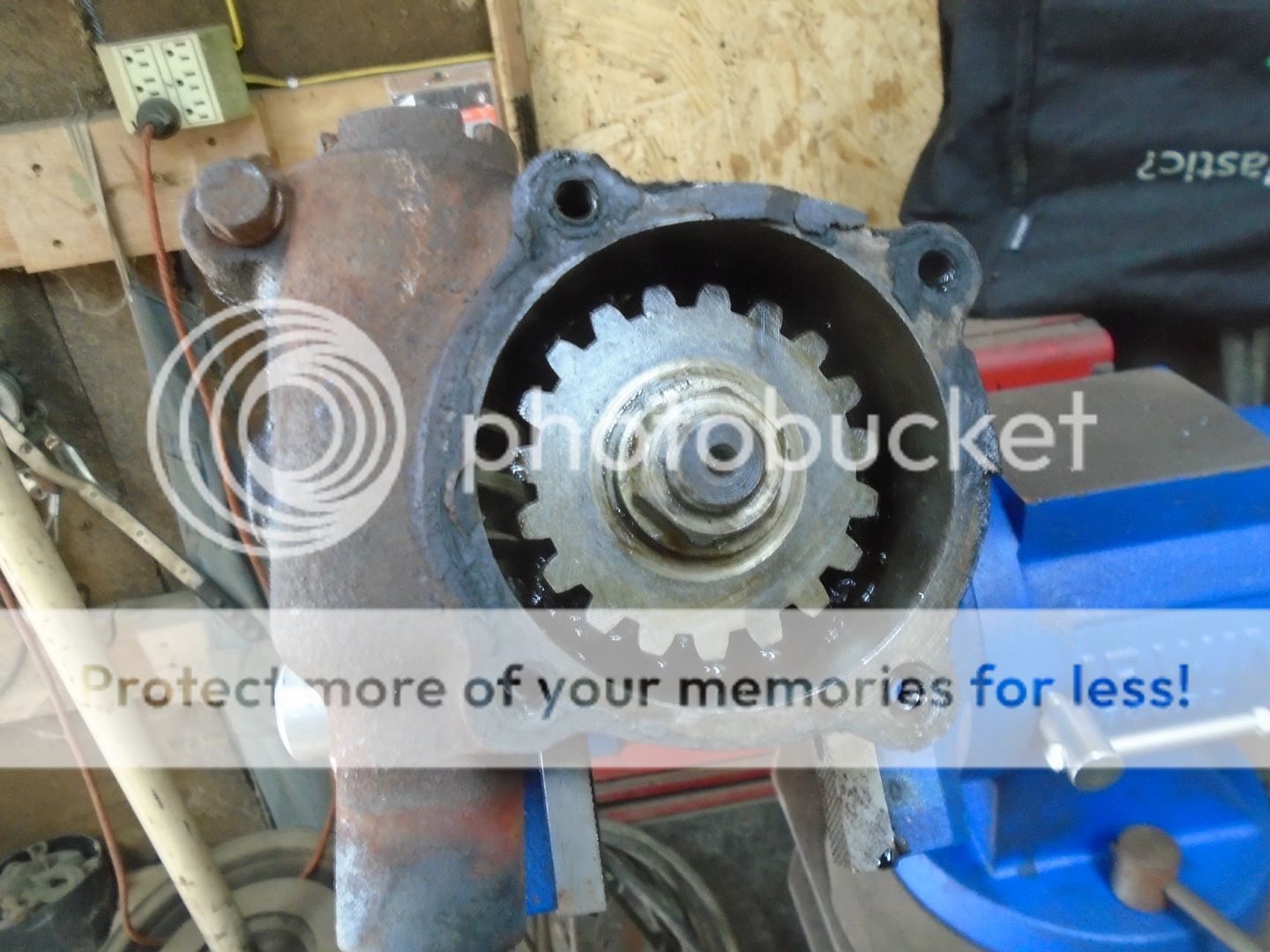
My next problem is that someone has welded a piece of flat steel to the cover on the steering box and they welded two of the bolts also.


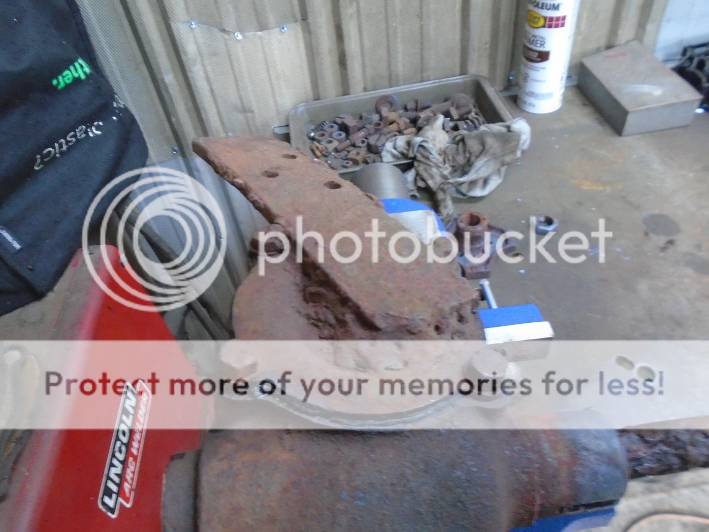
I cut the welds with a torch to remove the piece of steel.


After removing the cover, you can see that the gears are in good shape.


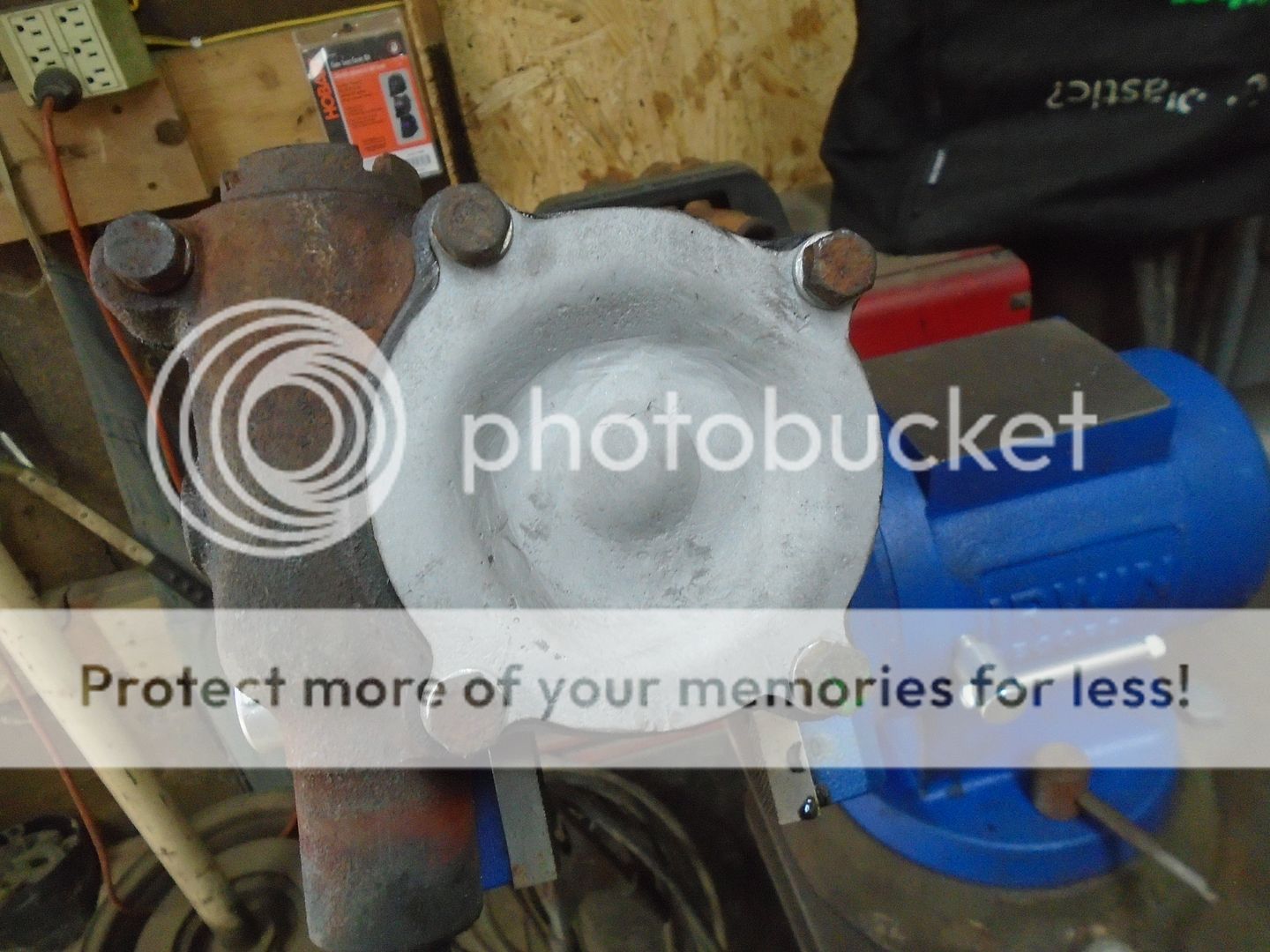
I clamped the cover up on the lathe.
This lets me hold it securely and still be able to rotate it as I grind the welds down with a small air grinder.


Here's how it looks mounted back onto the steering box.


Instead of splines like on a more modern steering shaft, this has a taper with a keyway to hold the steering wheel.


At this point I ran into something that has never happened to me before.
I have had this old wooden steering wheel for well over 40 years.
This steering wheel has a taper with a keyway and If you look closely you can see that the center of the steering wheel is the same size and shape as the part that came off this steering column.


And this wood steering wheel fits perfectly on this steering shaft.
I am convinced that this steering wheel came off the same model of car that this steering column came out of.

I am most likely going to have to shorten this steering shaft so when I cut it off, I'll put the end that the steering wheel fits on up on the lathe and cut new threads into the end of it.

 
I lifted the front of the tractor up so I could work on the steering.
Two holes were drilled into the underside of the frame and an exhaust clamp was used to mount the steering box to the frame.


With that mount under the frame in place, I then added another exhaust clamp mount to the outside of the frame so the steering box is held in place by two 3/8 diameter clamps.


I had mentioned earlier that the steering column would have to be shortened.
As you can see here, it will definitely have to be shortened.

 
The steering shaft has 7 inches cut out of it.
Before I put the pieces back to together, I put the end piece in the lathe and threaded it so I can put a nut on the tighten up the steering wheel.


I drilled some holes thru the sides of a piece of steel tubing and I drilled it out with a 47/64 drill ( .734 diameter ).


Then I used a 3/4 inch reamer to bring it out to the finished size.


The sleeve is slid onto the steering shaft and the end piece of the steering shaft is slid into the sleeve.
The steering shaft is then welded thru the holes in the sleeve.


When it cooled off enough, I then primed it.


The steering shaft housing has also been shortened 7 inches and the parts are primed.

 
As a reminder, this is what the engine looked like when I got it.


I have taken all of the controls off the top of the engine.
I'm going to leave the housing that is covering the spark plug and I will be using that lever on the side of it that shuts the engine off.


I also removed the voltage regulator from the top of the starter / generator and that will be mounted down under the floor plate, by the battery.


I have this gas tank mount that someone has done a lot of brazing on.
It is off a Wisconsin engine but I'm going to use it for mounting the gas tank on this Briggs engine.


I made up this mounting plate that will bolt onto the back of the engine and the gas tank mount will then bolt to it.


Here is a view of the tractor with the gas tank mounted.


And a couple of closeups of the gas tank.


This is the bracket on the steering column for the throttle and choke control levers.


This bracket clamps onto the lower part of the steering column with holes in the two tabs to support the lower end of the control levers.
I have added a piece of metal above each tab so I can clamp the throttle and choke cable housings to them.


Up on the steering column, I need something for the control levers to ride against so I'm cutting out two pieces of nylon like this.


These fit into the brackets for the control levers.


Two pieces of 5/16 steel rod are bent into the shape needed for the control rods.


The levers are flattened out on the ends.


And the rods are threaded on the lower ends.


This gives you an idea of how they will look when assembled on the steering column.


The lower ends of the rods will have these springs with nuts threaded up on the rods to hold tension on the them.

 
To make the levers that the throttle and choke cables will attach too, I first brazed two pieces of round steel onto a piece of flat steel.


Then I cut the shape of the levers out of the flat steel.


Holes were drilled into round part so it will fit on the control rod and a small hole was drilled in the end of each lever for the cable to attach to.
Both of the levers are mounted on the control rods and assembled onto the steering column.


Here is how the steering column looks so far.


Back
Top