When we moved down to Madison, Indiana, I hadn't planned on building any more tractors and I have actually sold some of my tractors since we moved here.
However .. under the circumstances .. I'm glad that this tractor became available to me now because it gives me an interesting and challenging project to work on and it helps take my mind off other things.
.......................................................................................................................................................................
So ... for those of you that may have missed my previous post looking for information .. I'll start here at the beginning.
This is what is left of a small tractor that I picked up at the last show I was at.
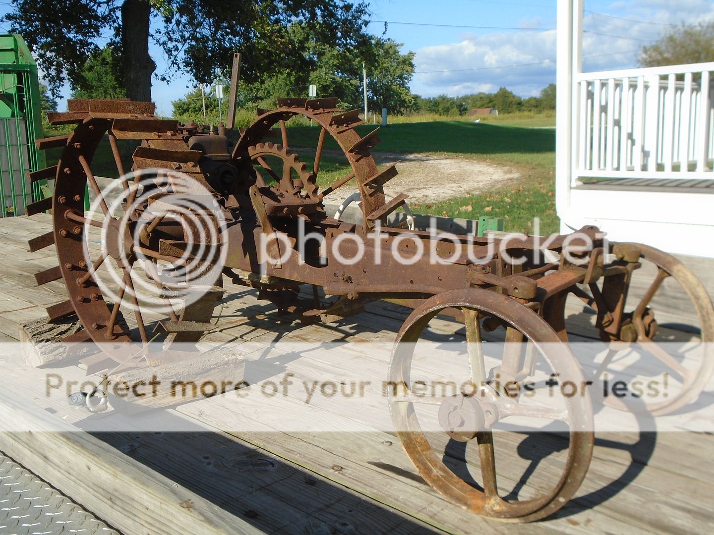
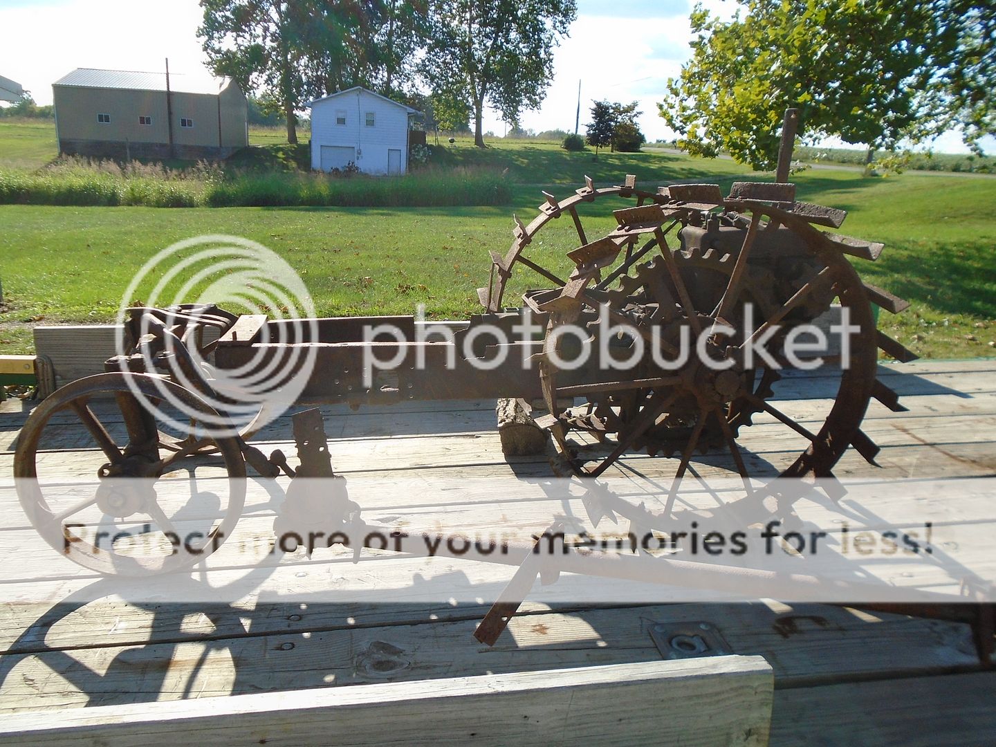
I had no idea of what it was when I got it and I have since learned that it was originally a Centaur, 2-wheel, walk-behind garden tractor that was built from 1923 thru 1925.
This is how the design of the tractor looked from the factory.

Some one had converted it into a riding tractor a long time ago and I'm going to rebuild it as a riding tractor.
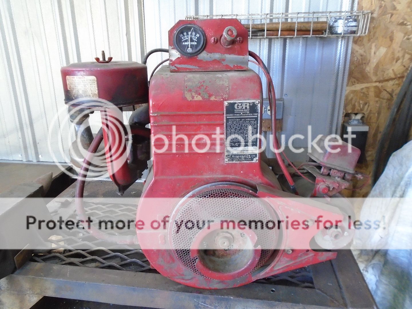
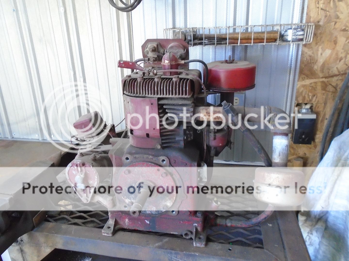
My son gave me this 9HP Briggs & Stratton engine that was built in 1957 and I'm going to use it to power this tractor.
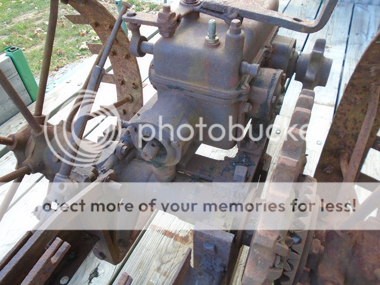
The input shaft on the transmission is in the front and it had a clutch between the engine and the transmission.
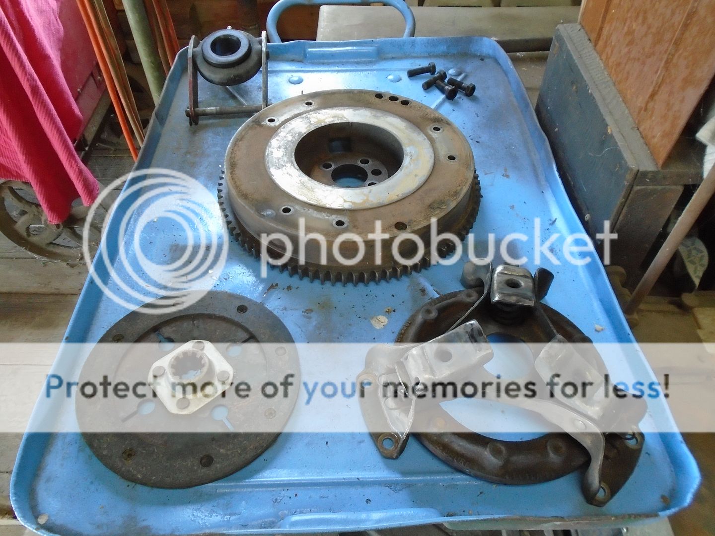
I want to put the Briggs engine inline like the original engine was and I need to make a clutch system for it so I picked up this flywheel and clutch parts off a Farmall Cub to put on the Briggs engine.
I'm using a piece of 3" diameter steel to make the flywheel adapter out of.
This is chucked up in my lathe and both ends have been squared off.
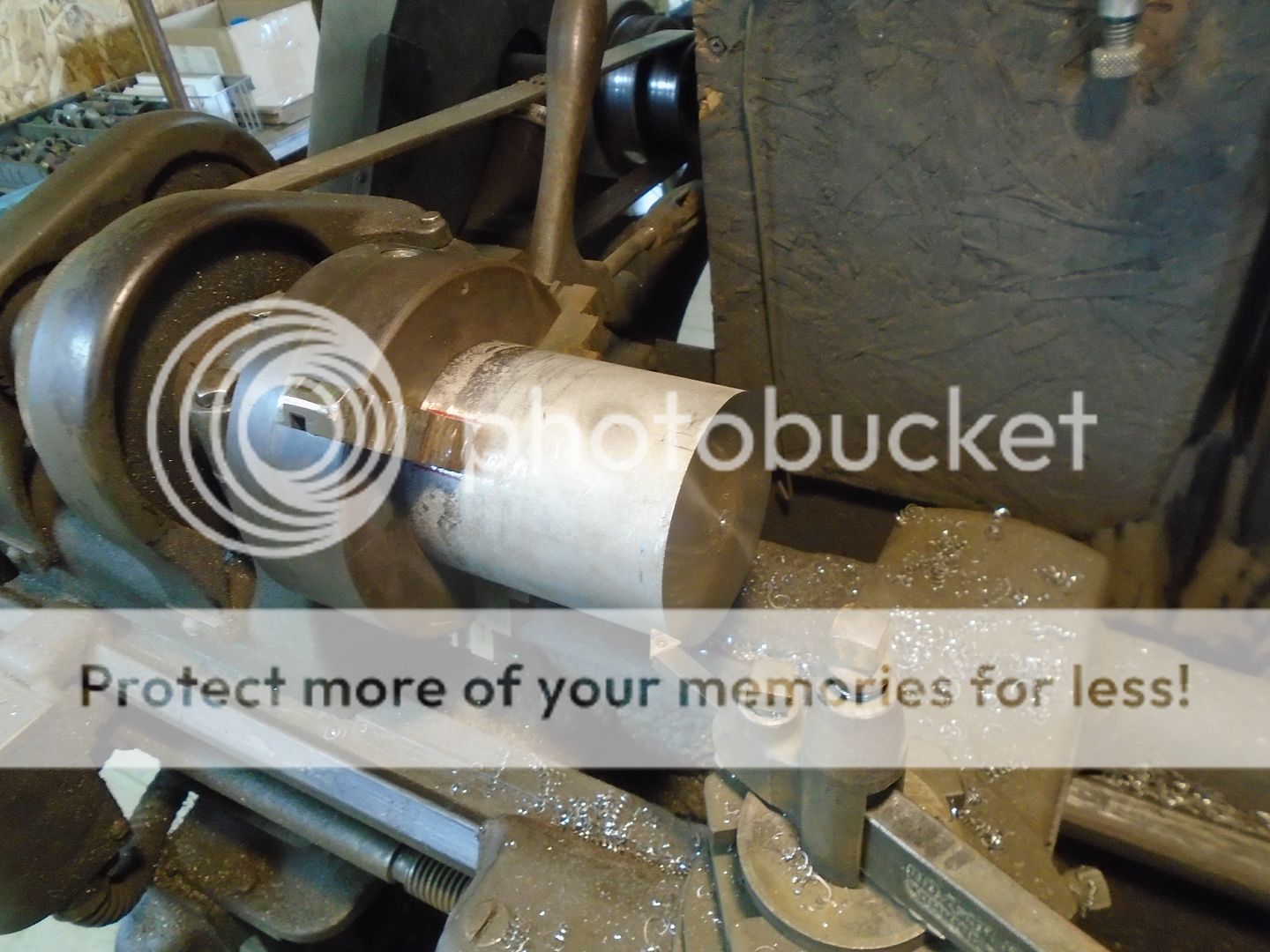
Then I bored it out to fit on the Briggs crankshaft.

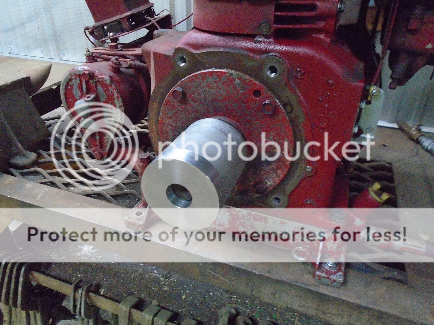
It fits snugly onto the crankshaft.
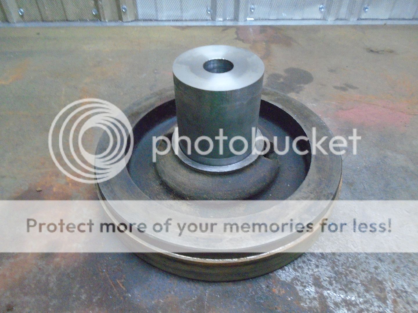
And it also fits snugly into the back of the flywheel.
The Briggs engine has a starter/generator on it already so I removed the starter ring gear from the flywheel.
The crankshaft sticking out the back of this engine does not have a keyway in it so I need to come up with a good way to lock this flywheel adapter so it won't spin on the crankshaft.
I have four 3/8-24 setscrews that have a pin boss machined on the end of them and three regular setscrews and I'm going to use them to lock the flywheel onto the crankshaft.

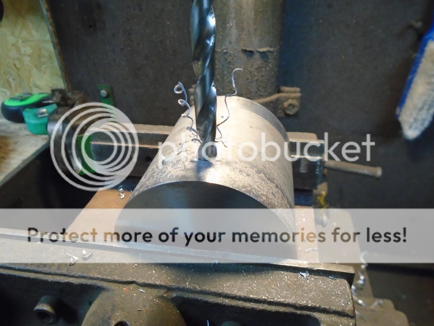
First I drill and tap three holes on the end of the adapter that goes toward the engine.
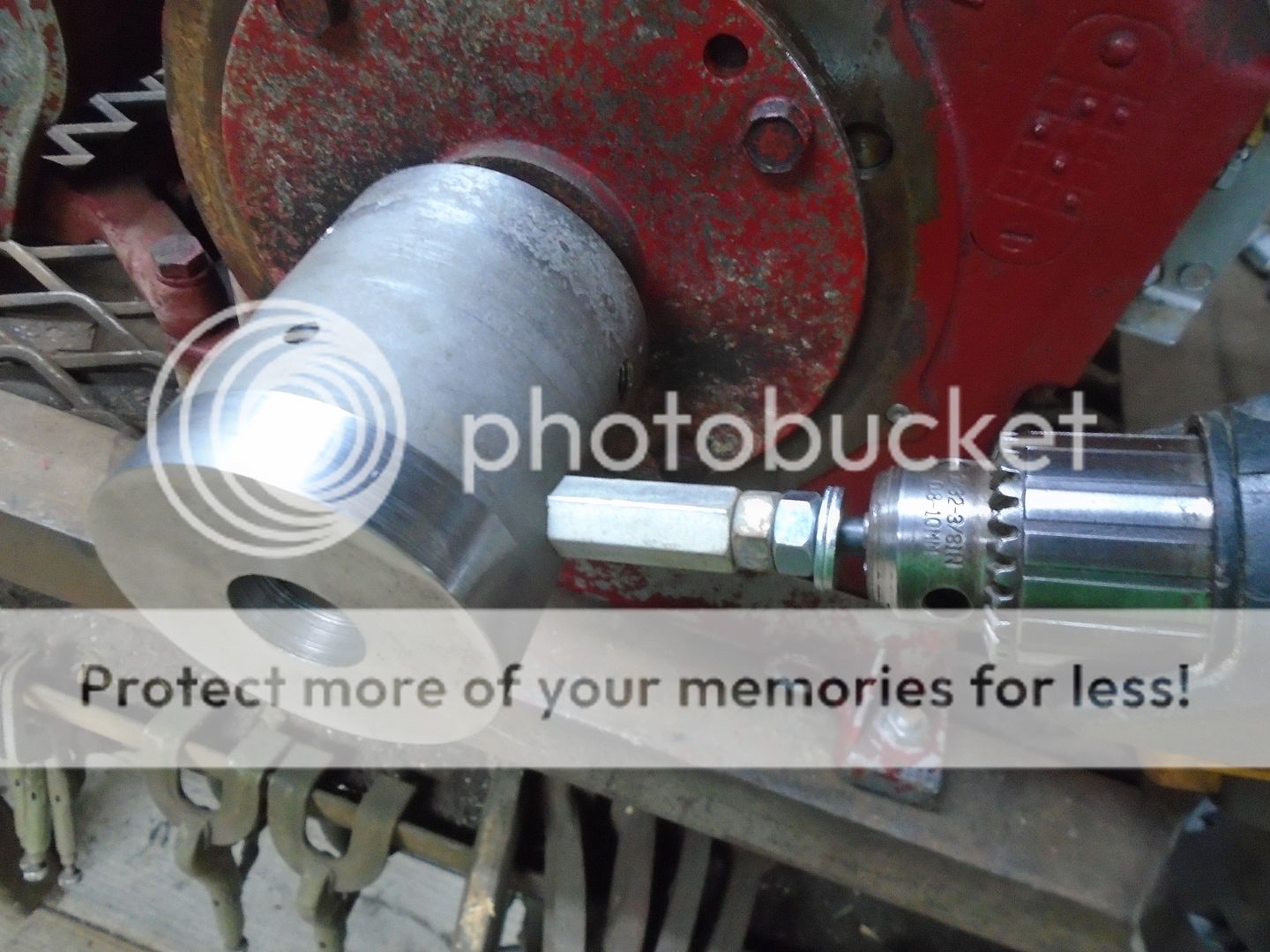
Then I turn the adapter around and drill four holes that are .002 larger then the diameter of the pin boss on the set screws.

The adapter is slid onto the crankshaft and tightened down with the three setscrews.
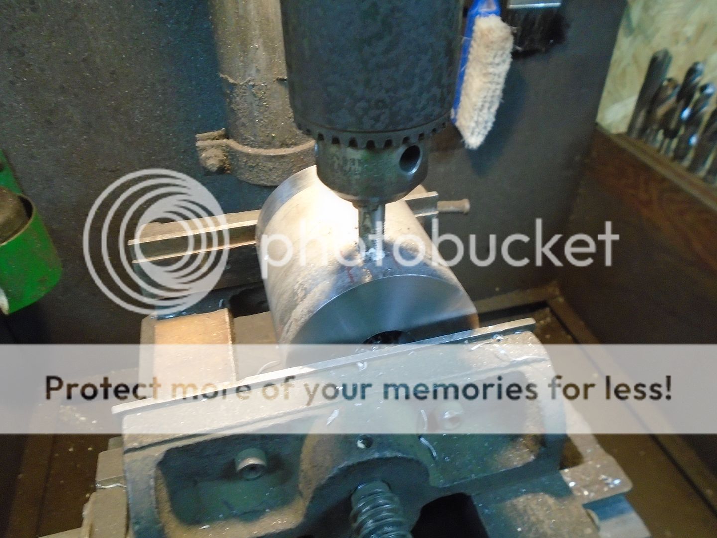
Then the four locating holes are drilled into the crankshaft.
I'm using spacers on the drill so all of the holes are drilled to the same depth.
The pin boss on the ends of the setscrews will set down into these holes and keep the adapter from rotating on the crankshaft.
When I tighten the seven set screws in the adapter down onto the crankshaft, I will then screw another set screw down on top of those first setscrews to lock them in place.

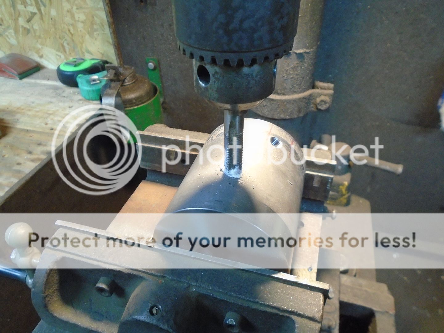
The adapter is set back up in the drill press and the four holes are then drilled out and tapped.
However .. under the circumstances .. I'm glad that this tractor became available to me now because it gives me an interesting and challenging project to work on and it helps take my mind off other things.
.......................................................................................................................................................................
So ... for those of you that may have missed my previous post looking for information .. I'll start here at the beginning.
This is what is left of a small tractor that I picked up at the last show I was at.


I had no idea of what it was when I got it and I have since learned that it was originally a Centaur, 2-wheel, walk-behind garden tractor that was built from 1923 thru 1925.
This is how the design of the tractor looked from the factory.

Some one had converted it into a riding tractor a long time ago and I'm going to rebuild it as a riding tractor.
My son gave me this 9HP Briggs & Stratton engine that was built in 1957 and I'm going to use it to power this tractor.


The input shaft on the transmission is in the front and it had a clutch between the engine and the transmission.

I want to put the Briggs engine inline like the original engine was and I need to make a clutch system for it so I picked up this flywheel and clutch parts off a Farmall Cub to put on the Briggs engine.

I'm using a piece of 3" diameter steel to make the flywheel adapter out of.
This is chucked up in my lathe and both ends have been squared off.

Then I bored it out to fit on the Briggs crankshaft.

It fits snugly onto the crankshaft.

And it also fits snugly into the back of the flywheel.
The Briggs engine has a starter/generator on it already so I removed the starter ring gear from the flywheel.

The crankshaft sticking out the back of this engine does not have a keyway in it so I need to come up with a good way to lock this flywheel adapter so it won't spin on the crankshaft.
I have four 3/8-24 setscrews that have a pin boss machined on the end of them and three regular setscrews and I'm going to use them to lock the flywheel onto the crankshaft.

First I drill and tap three holes on the end of the adapter that goes toward the engine.


Then I turn the adapter around and drill four holes that are .002 larger then the diameter of the pin boss on the set screws.

The adapter is slid onto the crankshaft and tightened down with the three setscrews.
Then the four locating holes are drilled into the crankshaft.
I'm using spacers on the drill so all of the holes are drilled to the same depth.

The pin boss on the ends of the setscrews will set down into these holes and keep the adapter from rotating on the crankshaft.
When I tighten the seven set screws in the adapter down onto the crankshaft, I will then screw another set screw down on top of those first setscrews to lock them in place.

The adapter is set back up in the drill press and the four holes are then drilled out and tapped.