Back on the powered lawn roller idea - part 2

The new alternator/stator is mounted on the front of the engine and I have put the flywheel back on.
Here you can see that the old voltage regulator is mounted up on top of the flywheel shroud.
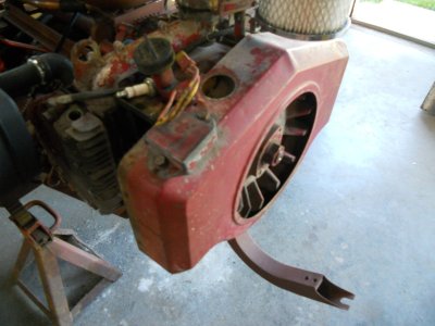
DSCN0596.JPG


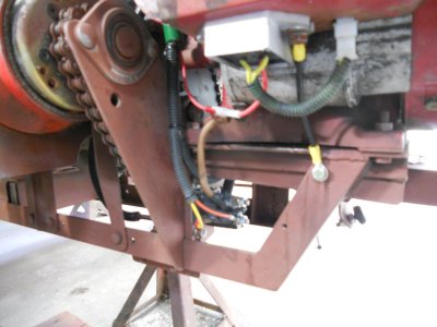
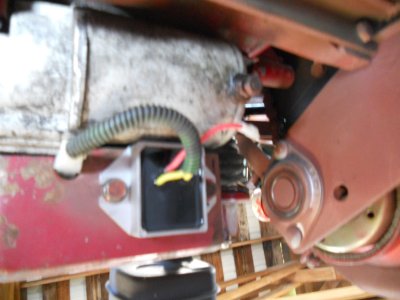
I have mounted the new voltage regulator down under the side of the shroud next to the starter.
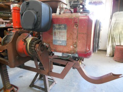
DSCN0602.JPG


The fan pulley and screen are fastened on the front of the flywheel. I also put two screws into the mounting holes for the old voltage regulator and I found a rubber cap that fits the large hole in the top of the shroud.
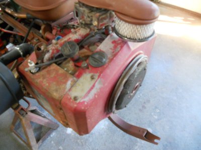
DSCN0599.JPG


I'm assuming the red wire on the voltage regulator goes to the amp gauge and then on to the battery terminal on the switch ?
DSCN0603.JPG


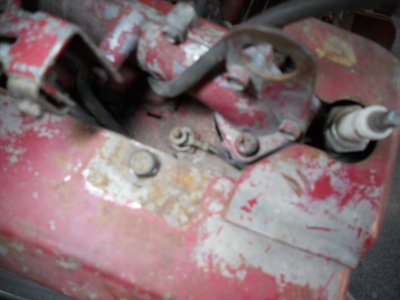
On the left side of the engine there is a terminal that has a black wire coming up from the coil.
Assuming again, this is to connect a wire that will ground out the coil to stop the engine ?
DSCN0600.JPG
 
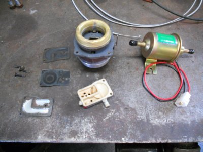
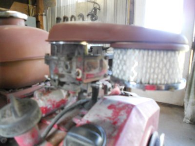
I've put a new fuel inlet needle and seat and gasket on the top part of the carb.
The fuel pump body is setting on the bench and you can see that the fuel inlet barb is broken on the left side of it.
After seeing how this original pump works, I have decided that I'm not going to use it and use the small electric pump instead.
The electric pump is rated at 2.5 to 4 pounds pressure.

The fuel outlet on the lower gas tank is about 3 foot behind and 18 inch below the carburetor.
When the fuel line is empty, the engine is going to have to crank over awhile before the fuel is finally sucked all the way up to the carb.
With the electric pump, I'll have fuel at the carb before I first turn the engine over.

I drain the tank and line and run the carb dry every winter so this would be a concern every spring and anytime that I may run it out of gas.

DSCN0604.JPG


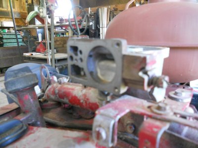
Looking at the round pump cavity on the front of the carb, the fuel is drawn into this cavity thru the small hole in the lower left side.
Then it is pushed out of the pump cavity and into the float bowl thru the small hole in the upper side of the cavity.

DSCN0605.JPG


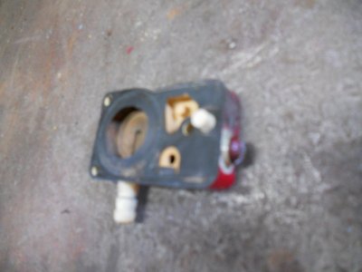
I trimmed the broken inlet barb down flat on the side of pump body. Then I tapped it and threaded a screw into it with Loctite on the threads.
The center is cut out of the pump diaphragm gasket. With the fuel line hooked to the old vacuum hose barb, the fuel will now go right into the round pump cavity on the carb and thru the small upper hole and into the float bowl.

DSCN0607.JPG


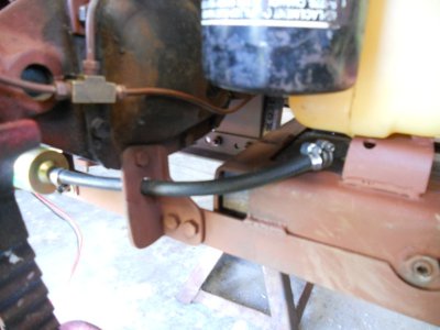
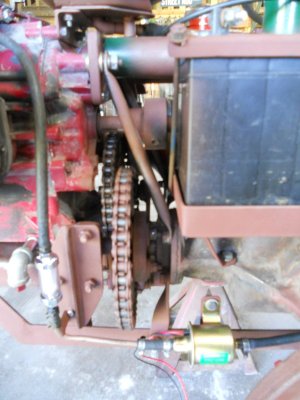
The fuel comes out of the bottom of the lower tank and goes to the inlet side of the fuel pump.

DSCN0610.JPG


Then it passes thru a filter and the hose runs up the back side of the engine.

DSCN0609.JPG


The hose goes under the intake manifold and connects to the underside of the old fuel pump body.

DSCN0608.JPG
 
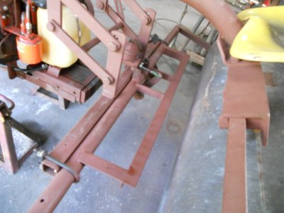
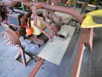
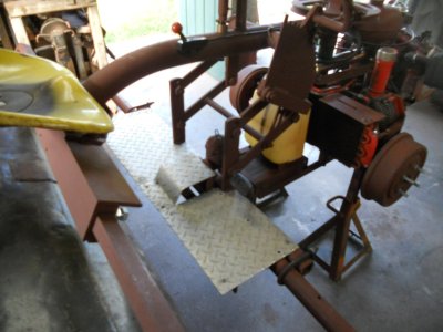
A angle iron frame is welded to the round pipe that fastens to the toolbar.

DSCN0615.JPG


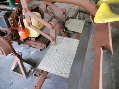
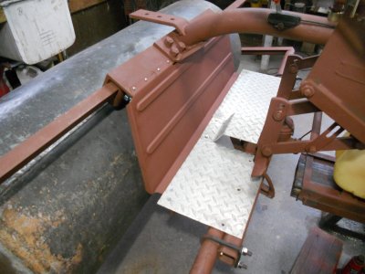
Two pieces of salvaged aluminum diamond plate are fastened to it for footboards.

DSCN0617.JPG


Another piece of the diamond plate is bent up and fastened in place to cover the brake linkage.

DSCN0618.JPG

DSCN0619.JPG
 
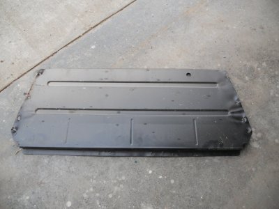
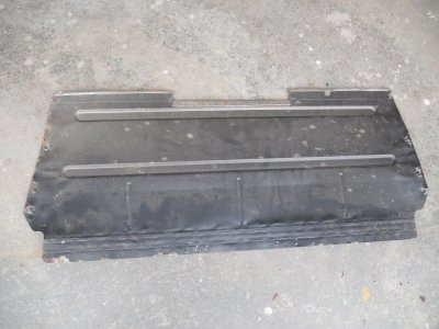
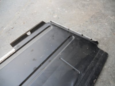
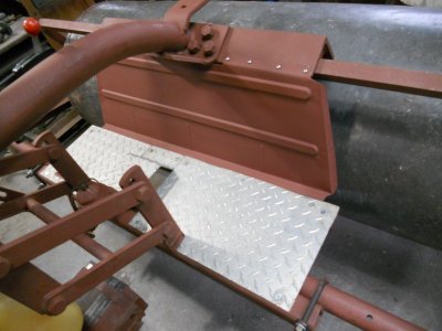
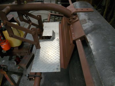
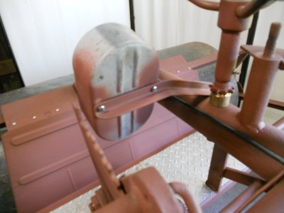
I want to add a guard panel in front of the roller to keep me from accidently catching my foot down between the footboard and the roller and also to keep the roller from throwing anything up on the backs of my legs.
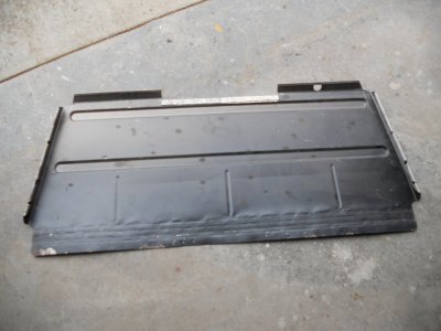
I have this sheet metal panel with indented ribs already stamped into it that looks like it is just about the right size.

DSCN0620.JPG


I have somewhat flattened the bends out of it along the bottom edge.
Then I bent over about 1/4 inch of metal along the top and hammered it down flat to strengthen the edge and make it smooth.
A notch is formed in the center for clearance under the seat area.
About an inch of the metal is then bent up a little along the top edge on either side of the center notch.

DSCN0621.JPG


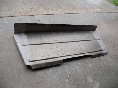
3/4 inch of metal is bent over on the side. This is rolled over to leave a gap instead of hammered flat like the top edge was. This roll over makes the edge stronger than a flat hammered edge.
1 inch is then bent up to form a 90 degree angled edge.

DSCN0622.JPG


This was done to both sides.

DSCN0623.JPG


Finally, the wrinkles are smoothed out of the bottom area better with a hammer and dolley and a 3 inch strip is bent over.

DSCN0624.JPG


The panel is primed and fastened in place.

DSCN0625.JPG

DSCN0626.JPG

DSCN0627.JPG
 
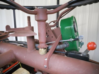
The throttle lever is mounted on the side of the frame.
I'm forming a piece of 3/4 angle iron to fit around the tube frame.

DSCN0628.JPG

DSCN0630.JPG


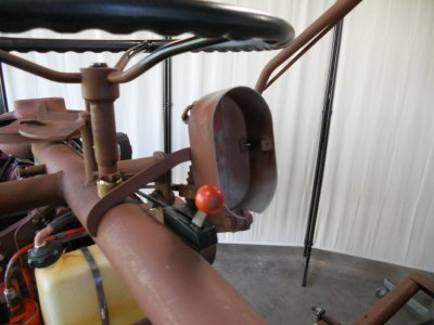
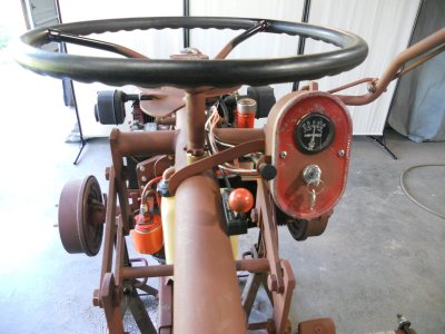
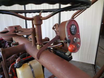
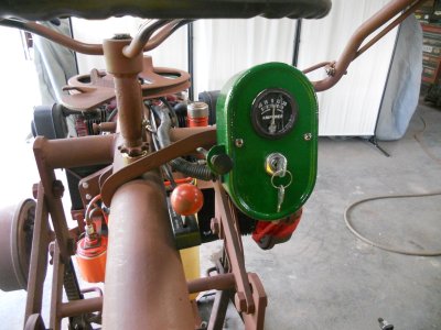
The Farmall gauge box bolts onto this piece of angle iron.

DSCN0631.JPG

DSCN0632.JPG


This is how it looks with the faceplate on.

DSCN0634.JPG


The choke cable is fastened to the side of the gauge box.
The wiring comes out thru a hole in the side. This hole will have a rubber grommet in it and the wires will get the plastic loom on them once everything is painted.

DSCN0636.JPG
 
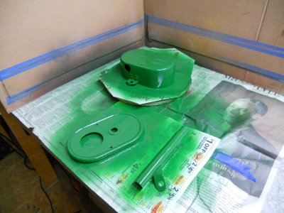
Getting ready to run the wiring. It's a little too cold outside for painting so I brought the gauge box inside and painted it in the train room.
With it already painted, I can go ahead and make up the complete wiring harness. Then when I'm ready to paint the rest of the roller, the complete wire harness with the gauge box can be removed as and assembly.

DSCN0637.JPG
 
The gauge box is mounted and the wiring is run.
The engine turns over good but the new fuel pump that I bought doesn't work.

DSCN0638.JPG


The hole for the wires in the gauge box has a rubber grommet to protect the wires.

DSCN0639.JPG


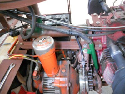
Just behind the engine, there is a steel tube with a fiber insulating tube inside it that the wires go down thru.
This keeps the wires away from the drive chain and from the heat off the engine.

DSCN0640.JPG


The wires come out of the steel tube under the engine.
I intend to make a sheet metal panel to cover this area.

DSCN0642.JPG


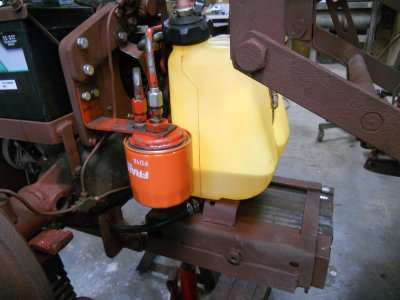
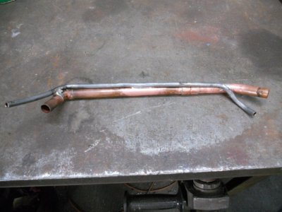
My idea of the 5/8 copper tube to feed the fuel down into the lower tank didn't work out so well.
As I put the gas into the upper tank, I could hear the air chugging out of the lower tank and It took over a minute to get this much gas into the tank.

DSCN0642-1.JPG


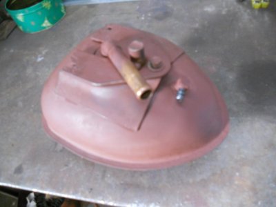
So I soldered a hose fitting into the bottom of the upper tank for and air release line.

DSCN0643.JPG


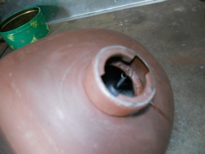
You can see on the inside that there is a steel line that comes up from the fitting so the opening in the the air line is right up by the fill neck.

DSCN0644.JPG


Another steel line is soldered to the underside side of the copper tube. This line will be painted the same color as the rest of the machine.

DSCN0645.JPG


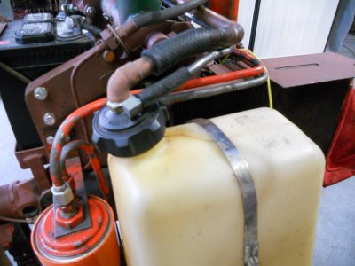
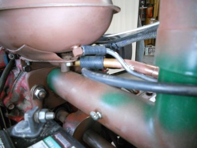
This is how the fuel line and the air line connect to the lower tank.

DSCN0646.JPG


And how they connect to the upper tank.

DSCN0648.JPG
 
Last edited:
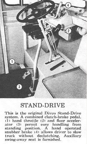
This photo shows the controls for a 1940's Divco milk truck.
#4 shows the long lever sticking up from the floor with a "S" curve formed into it at the top.
This is the snubber brake handle that can be used to slow the truck down without depressing the clutch.

divco.png


I had a 1946 Divco that I sold shortly after we moved to Madison, Indiana.
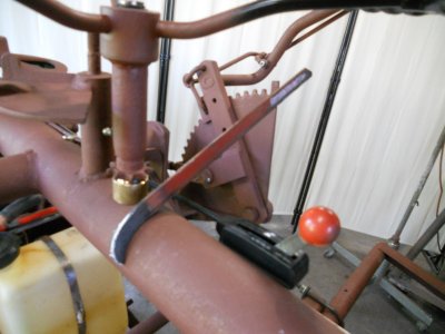
I still have that long brake handle and I'm going to use part of it for the control lever for the hydrostatic transmission.
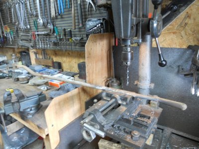
Here I have heated it up and straightened out the curve and I'm drilling a hole in it for the pivot point.

DSCN1160.JPG


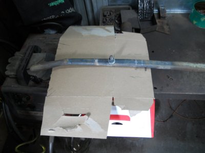
This is mounted on a bolt that is clamped in the vice and I'm determining how much the end of the handle will move with different positions of where the transmission cable would be mounted to it.

DSCN1161.JPG


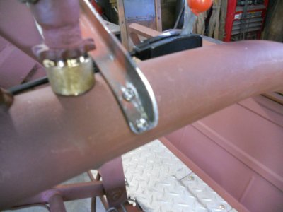
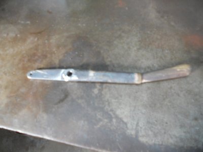
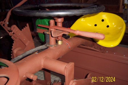
This is the finished transmission lever.

DSCN1162.JPG


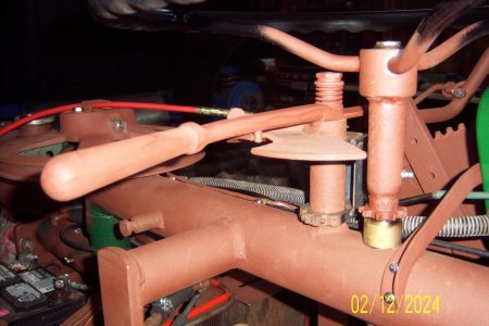
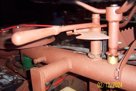
It is primed and mounted on the Ridemaster frame in the same position as the original drive lever.
The pivot point has a spring tightened down onto the lever.

100_3924.jpg


There is a 1/4 inch diameter pin on the underside of this lever.
This pin comes up against a stop that is formed into the metal of the base plate.
This determines the position of the lever with the transmission in neutral.

100_3925.jpg


The spring on the pivot point allows the lever to be easily lifted up and over the stop to move the lever forward and drive the roller forward.

100_3926.jpg
 
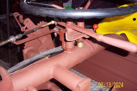
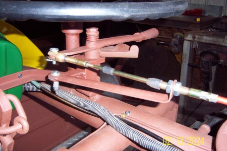
I have made up a bracket that clamps to the round tube coming up from the frame for the drive control lever mount.
This bracket extends out to the left and the flat bracket for holding the cable housing in place is fastened to it.

100_3932.jpg


The end of the cable bracket can pivot on the bracket that is fastened to the round tube.
This is necessary so the cable can flex sideways when the drive unit is turned for going around corners.

100_3933.jpg


Youtube link for video of the test run.

 
Back
Top