Reccomended procedure is to make a cut on the backing plate on the lathe you are going to use the chuck on then mount the chuck. If you don't know that was done you don't know if the runout is in the chuck or the plate. Like I said there are many tutorials on the web/utube. DonI like the idea of marking a jaw, and my work. I will start doing that!
Don, it does have a backing plate mounted chuck. It has 3 bolts, and 2 location pins.
You are using an out of date browser. It may not display this or other websites correctly.
You should upgrade or use an alternative browser.
You should upgrade or use an alternative browser.
My new 1943 South Bend 9c lathe
- Thread starter Ryan313
- Start date
Reccomended procedure is to make a cut on the backing plate on the lathe you are going to use the chuck on then mount the chuck. If you don't know that was done you don't know if the runout is in the chuck or the plate. Like I said there are many tutorials on the web/utube. Don
Do you mean to face it off?
Best to watch some of the videos on the net for more information. There is much more to it than I can cover here. Actually much more to it than I know. If the backing plate doesn't run concentric to the spindle the chuck won't either. If a chip is caught it the thread or the register of the plate it will likely have runout. If not it will have runout when the chip comes out. There is a register surface between the spondle and the plate and another register surface between the chuck and the plate. It is best to just live with the runout until you are dead sure you understand. DonDo you mean to face it off?
Best to watch some of the videos on the net for more information. There is much more to it than I can cover here. Actually much more to it than I know. If the backing plate doesn't run concentric to the spindle the chuck won't either. If a chip is caught it the thread or the register of the plate it will likely have runout. If not it will have runout when the chip comes out. There is a register surface between the spondle and the plate and another register surface between the chuck and the plate. It is best to just live with the runout until you are dead sure you understand. Don
Thanks for the advice, I will read into it!
I ordered a live center last week, it came in today! I found a piece of 1” stock about 6-8 inches long and gave it a try. Tail support got rid of all of my chatter problems. Here is a picture of the stock I was playing with.
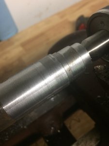
The finish was not very good, and when running my finger on it, it actually felt sharp. I remembered seeing a YouTube video that said a rounder tool leaves a better finish, so I took a trip to the bench grinder before doing a few more passes.
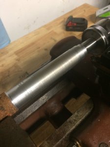
I am much more pleased with the finish after rounding the tool some. I want to make one of those captured nut desk toys just so I can get some practice with different operations.

The finish was not very good, and when running my finger on it, it actually felt sharp. I remembered seeing a YouTube video that said a rounder tool leaves a better finish, so I took a trip to the bench grinder before doing a few more passes.

I am much more pleased with the finish after rounding the tool some. I want to make one of those captured nut desk toys just so I can get some practice with different operations.
Your catching on fastI am much more pleased with the finish after rounding the tool some.

I was going through the same issue you were having. Found I had a bent spindle. Had a local machine shop make a new spindle and backing plate for the chuck. He has done work for me before and is very particular. Can't make a true spindle with a bent spindle in the lathe so had to go with him. I use the 3 piece replaceable tip cutting tools and QCTP with different holders. Make for quicker changing of tools. Have fun with your lathe Ryan.
Can't make a true spindle with a bent spindle in the lathe so had to go with him. That is one of the fun things about a lathe. If your spindle will turn at all you can likely mount a center point in it and cut that to concentric. Once you have a concentric center point in your headstock if you have the length you can mount a shaft between centers and turn your self a new spindle.which will be straight. Although he will complain constantly a good machinist can produce some fine high precision work on a junk machine. Don
Although he will complain constantly a good machinist can produce some fine high precision work on a junk machine. Don
That's how you know we are still alive!
Once you have a concentric center point in your headstock if you have the length you can mount a shaft between centers and turn your self a new spindle.which will be straight. Don
How can one turn a shaft with a point at the head stock and tail stock ? ?
Face plate on the spindle, point in the spindle, lathe dog attached to the shaft engaging with the face plate. Simplest way to learn is to google "Turning between centers". I have gone so far as to use a piece of a inner tube and two gear clamps to drive a shaft. Had to take light cuts but I took all the cuts necessary. DonHow can one turn a shaft with a point at the head stock and tail stock ? ?
The lathe has been around for much longer than the lathe chuck. I don't know what the original first work holding method was but I would bet that between centers was close to it. DonNever heard about anything like that but I'm new to this too.
On many if not most lathes the spindle has a through hole so that long stock can be passed through the spindle and the end worked on. the through hole is often a taper the same or similar to the tail stock taper. A point can be set in the taper. With a solid spindle you would have to devise a way to screw a piece of stock on the spindle or mount it centered on the face plate then cut a center point on that stock. Then you could mount your work between that point and a point in the tail stock. Next you devise a way to turn your work. Your mind is your most important tool.
The only lathe that I know of with a 1/2 spindle is the Dunlap built lathe sold by sears. At one time there was a yahoo forum dedicated to them. Some of the more highly educated on that forum changing the material and structure of the spindle to strengthen it and the considered opinion seemed to be that the benefit didn't justify the effort. beefing up the spindle just moved the excessive forces to other parts of the machine which were not designed for those forces. This then produces chatter and poor finish. Not having a through hole in the spindle is not the end of the world but it is one more limitation to find a way around. Don
Very interesting about the face plates! The other day I saw a video from “this old tony” on YouTube where he made a faceplate for a new chuck he got. I will try to find it and link it. I have been watching a lot of machining videos lately, and learned that any chips can cause things to be misaligned. When I got the lathe the chuck was a bit gummed up, so I disassembled it and cleaned it. I did try to clean mating surfaces, but I did not clean them to the extent that I have seen in some videos. I will go through again and see if I can get better results.
Today I cleaned up the indicators a bit. Here was the starting condition. Overall, they were hard to read.
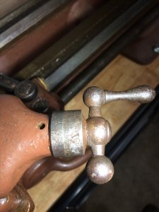
I used a Milwaukee m12 rotary tool and cleaned them a bit with a scotch-bright style wheel.
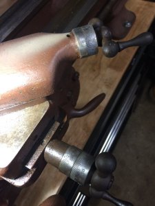
Once buffed I used black nail polish to paint the area.
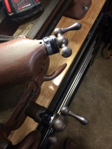
After a few minutes of drying, some acetone on a rag removes the excess paint and leaves it in the lower portions.
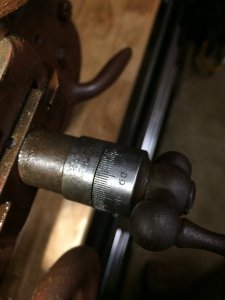
This process only takes a few minutes, and the results in person are much better than the picture. While I was doing this, I could not help but wonder why they made them so small! I understand it is a small lathe, but I think a 2-3” wheel instead of a 1” wheel would have helped immensely. I am just thinking aloud now, but I wonder if larger indicators can be installed without too much trouble.
I did not have any buffing wheels for the rotary, and it would have come out much better if it was polished, but that will have to wait for another day. Likely the day that I go though to clean and paint the entire machine.
Today I cleaned up the indicators a bit. Here was the starting condition. Overall, they were hard to read.

I used a Milwaukee m12 rotary tool and cleaned them a bit with a scotch-bright style wheel.

Once buffed I used black nail polish to paint the area.

After a few minutes of drying, some acetone on a rag removes the excess paint and leaves it in the lower portions.

This process only takes a few minutes, and the results in person are much better than the picture. While I was doing this, I could not help but wonder why they made them so small! I understand it is a small lathe, but I think a 2-3” wheel instead of a 1” wheel would have helped immensely. I am just thinking aloud now, but I wonder if larger indicators can be installed without too much trouble.
I did not have any buffing wheels for the rotary, and it would have come out much better if it was polished, but that will have to wait for another day. Likely the day that I go though to clean and paint the entire machine.
Nice work! Most lathes of that era have very small dials, I think folks had better vision back in the day. If you do some searching, there are asome web articles about fitting larger dials. But it may be easier and cheaper to do something like this: https://www.amazon.com/Yescom-Digit...ds=lathe+dro&qid=1563645647&s=gateway&sr=8-13 or this https://www.amazon.com/Hardened-Sta...ds=lathe+dro&qid=1563645704&s=gateway&sr=8-14Very interesting about the face plates! The other day I saw a video from “this old tony” on YouTube where he made a faceplate for a new chuck he got. I will try to find it and link it. I have been watching a lot of machining videos lately, and learned that any chips can cause things to be misaligned. When I got the lathe the chuck was a bit gummed up, so I disassembled it and cleaned it. I did try to clean mating surfaces, but I did not clean them to the extent that I have seen in some videos. I will go through again and see if I can get better results.
Today I cleaned up the indicators a bit. Here was the starting condition. Overall, they were hard to read.
View attachment 15599
I used a Milwaukee m12 rotary tool and cleaned them a bit with a scotch-bright style wheel.
View attachment 15598
Once buffed I used black nail polish to paint the area.
View attachment 15600
After a few minutes of drying, some acetone on a rag removes the excess paint and leaves it in the lower portions.
View attachment 15601
This process only takes a few minutes, and the results in person are much better than the picture. While I was doing this, I could not help but wonder why they made them so small! I understand it is a small lathe, but I think a 2-3” wheel instead of a 1” wheel would have helped immensely. I am just thinking aloud now, but I wonder if larger indicators can be installed without too much trouble.
I did not have any buffing wheels for the rotary, and it would have come out much better if it was polished, but that will have to wait for another day. Likely the day that I go though to clean and paint the entire machine.
