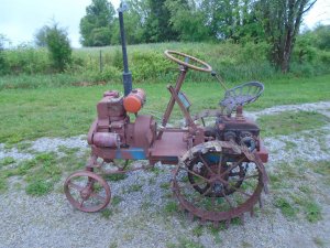
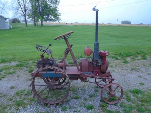
Winter project

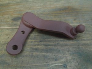
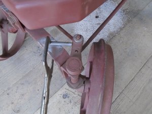
I made up a steering arm out of flat steel and welded it to the top of the tierod arm for the right wheel.

DSC02094.JPG


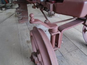
Here is how it looks mounted back on the tractor.

DSC02095.JPG


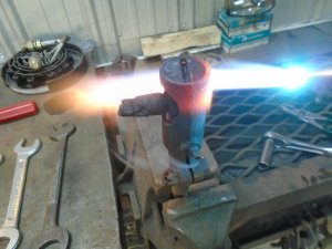
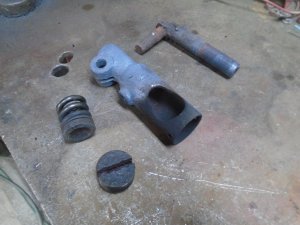
I'm using old Ford model-A tierod ends for the steering rod and they are all rusted up so I have to heat them up to get them apart.

DSC02092.JPG


Here are the pieces of one of them once I got it apart.

DSC02093.JPG


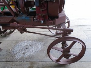
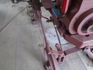
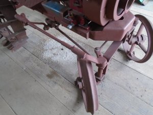
The steering rod is made up and installed.

DSC02097.JPG

DSC02096.JPG


Turning right.

DSC02098.JPG


And turning left.

DSC02099.JPG


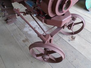
I need to weld a piece of steel rod onto the top of the axle as a stop to keep the wheel from rubbing the radius arm.

DSC02100.JPG


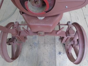
Here is the finished axle.

DSC02101.JPG
 
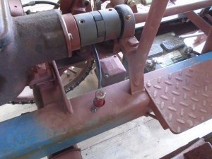
The voltage regulator is mounted down in between the frame rails.
This has a manual operated " foot switch " mounted on the frame to supply electric power to the starter/generator for starting the engine.
This starter switch makes a direct connection between the battery and the starter.

DSC02107.JPG


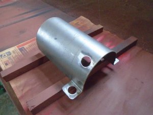
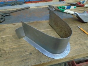
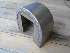
For those of you that have expressed concern about all of the moving parts on this tractor, you will be glad to finely see this piece of fabricated metal.

DSC02106.JPG


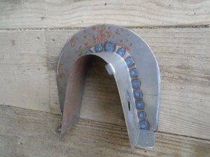
This is the first piece for making up the guards to cover the moving parts and it fits over the shaft between the engine and the flywheel.

DSC02104.JPG


This tractor does not have a key switch to start and stop the motor and the ignition coil on the engine's flywheel is energized as soon as the engine starts to turn over.
So .. if someone were to press down on that manual starter switch, the engine could start up.

To prevent this from happening at the shows, I'm going to put a master disconnect switch on the battery ground cable.
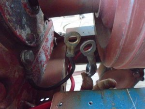
There are two cable ends in the area between the engine and the flywheel.
One is coming from the negative battery terminal and the other is bolted to the engine block.

DSC02108.JPG


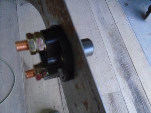
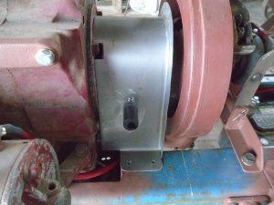
I have drilled a hole in the side of the sheet metal guard and mounted the switch to it.

DSC02111.JPG


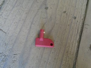
This on/off switch is operated by this key that can be removed during the show.

DSC02110.JPG


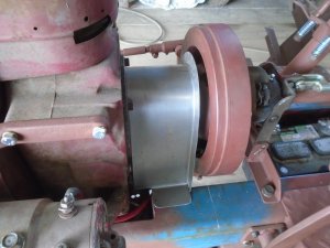
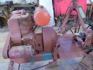
This is how it looks when the guard is on the tractor.

DSC02109.JPG
 
I used that same disconnect switch to disable my winch on my Kubota RTV to prevent someone activating it and pulling the end of my cable off. Kids and sometimes adults like to push buttons when they shouldn't! My switch resides under the seat.
 
The front face plate for the flywheel guard is cut out and welded to the first piece.

DSC02112.JPG


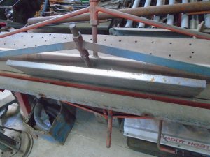
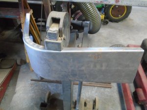
To start making the guard for the flywheel, a strip of metal is cut out and the two sides are bent at 90 degrees.

DSC02119.JPG


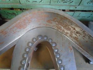
This part is the hardest piece to form because it has two edges that have to be shrunk together to form it evenly on both sides.

DSC02120.JPG


I'm using the front face plate as a guide for forming both sides of this piece.

DSC02121.JPG


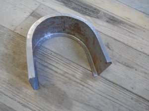
Here is the finished piece.

DSC02122.JPG


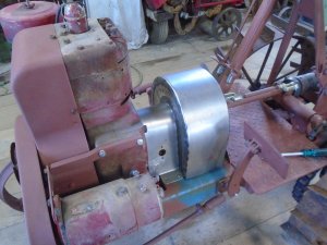
This piece is then welded to the front face plate and here is how it looks on the tractor.

DSC02126.JPG


With this still fastened onto the tractor, I traced the shape of the rear face plate on a piece of sheet metal and cut it out.
Then it was welded to the back end of the flywheel guard.

DSC02129.JPG


A piece of angle sheet metal was fit to the rectangle cutout for the throwout bearing and welded in place.
Then the guard was sand blasted and all the outside welds ground down smooth before it was primed.
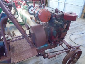
This is how it looks mounted back on the tractor.

DSC02131.JPG

DSC02130.JPG


I have also made up a box for the ammeter and mounted it to the steering column support.
This has room to put in a switch if I decide to put lights on the tractor later.

DSC02133.JPG
 
Outstanding job on the shields JD as posted obviously not your first go at that kind of thing I've done a fair amount of aircraft sheet metal work but never got involved in shrinking and then add the double bend kudos JD
 
Last edited:
This is the rear part of the drive shaft and even though it doesn't have anything really sticking out that would easily grab anything, I still want to put a guard over it.
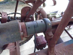
DSC02138.JPG


Here is what I formed up for it.

DSC02139.JPG


Here is how it looks mounted on the tractor.
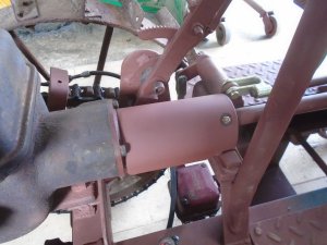
DSC02140.JPG


Next is to make up the throttle and choke cables.
There is already a bracket on the side of the engine to hold the throttle cable housing but there isn't a bracket to hold the choke cable housing.

I took the strap bracket off the bottom of the carburetor that holds the air cleaner in place and welded a piece of steel to it to clamp the cable housing to.
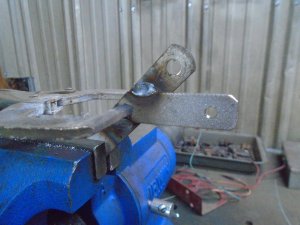
DSC02143.JPG


Both cables are mounted in place and hooked up.
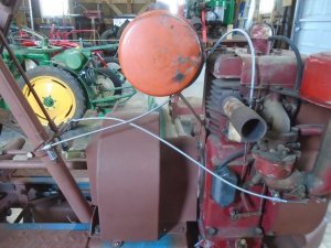
DSC02144.JPG


Here you can see how the choke cable housing is held in place on the side of the carburetor.
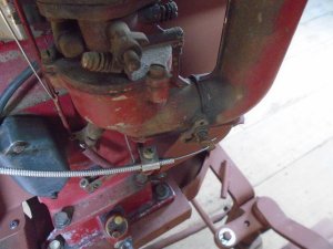
DSC02145.JPG


The other ends of the cables are mounted to the brackets and levers on the steering column.
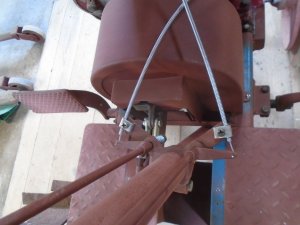
DSC02146.JPG


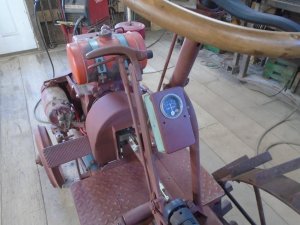
The cables are operated by the two levers under the steering wheel.
The throttle is on the right and the choke is on the left.
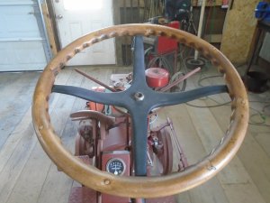
DSC02147.JPG


Tomorrow I should be ready to start it up and take it for a test drive. ............................................................


I haven't gotten as much done on building this tractor as I had hoped to during the winter and now that the weather is getting warmer, I being pulled away from it to work on other things.

I'm getting out some of my other tractors and getting them ready to start taking them to the tractor shows.
The last few times that I have had this Ridemaster running, I have noticed that it is starting to get a rod knocking noise so I have pulled the engine out of it to work on it.

The cylinder looks really good but as long as I have the piston and rod out, I've gone ahead and ran the hone in a few strokes and I'll put new rings in it also.
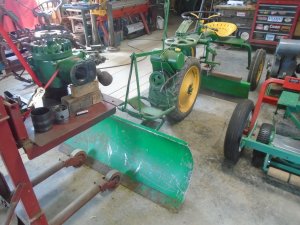
DSC02148.JPG


At the same time, I'm also working on the FMC.

It had been stored up in the loft all winter and when I pulled it down I saw that one of the original rear tires had blown out the sidewall on one side.
I bought two new tires and mounted both of them up on the tractor.

From the factory, this had two 1/2 inch dia. pins sticking out on either side of the drive belt and someone had cut them off.
These two pins keep the belt from flying out the sides when the engine it lifted up into the neutral position.

For the most part, this wasn't a problem but I have noticed that when I would drive the tractor around a lot and the belt would heat up some, then the tractor had a tenancy to creep forward in neutral.
With the belt being able to fly out on the sides, it pulled the bottom of the belt up enough that it would start to grab on the pulley when it was hot.
So I have welded two pins back in place to each side of the pulley and it doesn't creep any more.

However, it does make a nasty sounding clacking noise a few times every time the engine is lifted up into neutral position.
I figure that is why someone cut the pins off in the first place.

The clacking noise is caused by the metal connecting strip, that holds the two ends of the belt together, hitting the steel pins a few times before it stops spinning.
I'm going to make up two round sleeves out of Delrin/Acetal bearing material to fit over the pins.
This material will be able to rotate on the pins and I'm hoping that the metal connecting strip won't make as much noise against the plastic like material and may also be a little quieter with that material being able to rotate with it.

It is a total experiment so I'll see how it goes.
If it doesn't work, then I see if I can get a continuous flat belt made up so it won't have the metal connector strip.
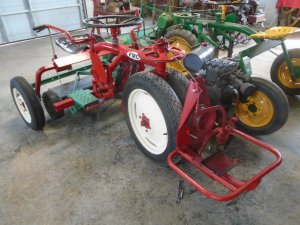
DSC02149.JPG
 
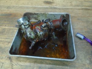
I pulled the carburetor off the tractor today and I'm using carb cleaner and a tooth brush to get the outside cleaned up.

DSC02171.JPG


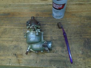
The outside of the carburetor cleaned up pretty good.

DSC02172.JPG


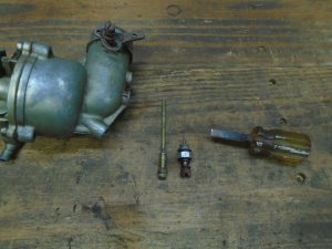
I ground the sides of an old screwdriver down so it fits into the hole and the metering tube unscrewed out easily.

DSC02173.JPG


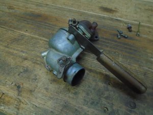
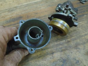
I'm using a putty knife to separate the gasket from the surface of the float bowl.
That way I can re-use the gasket if I can fix the leak without getting a rebuild kit.

DSC02174.JPG


The inside of the bowl looks surprisingly clean.

DSC02175.JPG


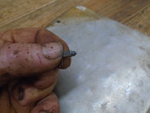
Here is the little culprit that is causing my problem.
If you look close, you can see that the end of the needle has a groove worn in it and that is allowing the gas to leak past it.

DSC02176.JPG


I called Napa and they had a rebuild kit in stock.
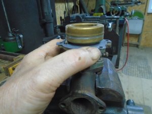
Here I'm resitting the the float level.

DSC02177.JPG


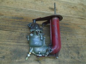
The carburetor is all put back together.

DSC02178.JPG


I bolted the carburetor back on to the engine and took the tractor out for it's first test drive.

DSC02179.JPG

DSC02180.JPG
 
Back
Top