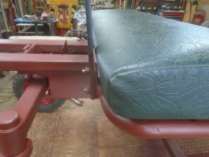
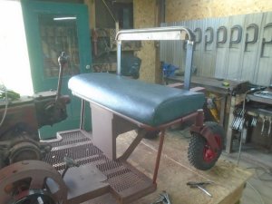
New project

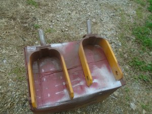
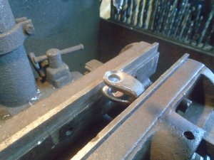
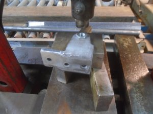
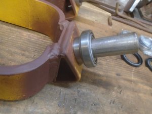
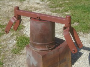
The swivel caster yokes that I'm going to use are the correct length but they are an inch to wide for the 6 inch long shoulder axle bolts that I have.
I need to make them narrower so the first thing to do was to cut them apart.
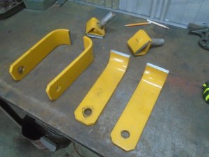
DSC03770.JPG


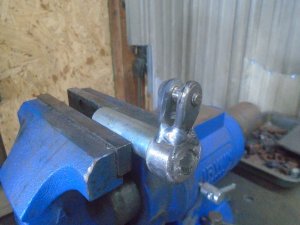
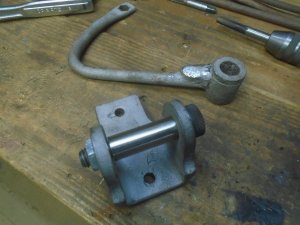
I made up a spacer tube the correct length and bolted the two arms together.
Then I welded them back onto the pivot mount.
I also welded a nut on one side that the shoulder bolt screws into and gets locked in place.
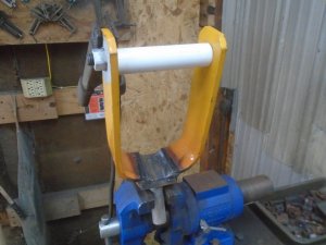
DSC03773.JPG


Both casters are done.

DSC03774.JPG


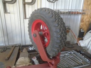
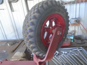
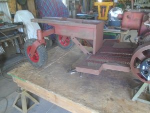
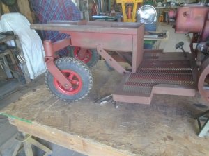
This gives you an idea of how they will look with the wheels mounted.
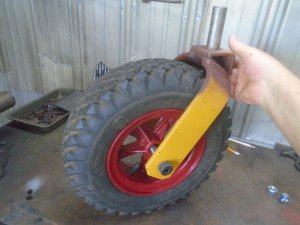
DSC03785.JPG


I'm still waiting on the bearings for these so I'll work on something else for awhile.
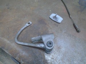
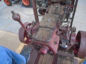
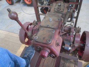
This tractor has band brakes on both sides and the operating lever is on the back side of the brake drum and pulls backward to operate the brakes.
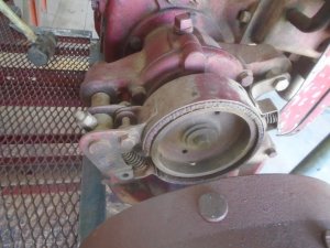
DSC03775.JPG


I don't want to have the operating linkage for the brakes in the area where my feet will be so I need to see if I can move the lever to the front side of the brake drum.
The mounting bolt for the brake assembly on the other side came off easily but this side doesn't want to move.
I ended up having to heat the housing up and it still took a long punch and a big hammer to get it out.
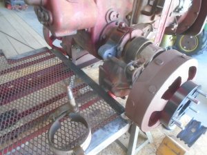
DSC03778.JPG


You can see here that the mounting hole in the back is 5/8 inch diameter and the mounting hole in the front is only 3/8 inch diameter.
I figure that I can take the brake assembly from the other side and move it over to this side but I have to drill the front mounting hole out to 5/8 inch diameter.
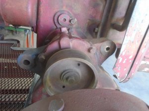
DSC03779.JPG


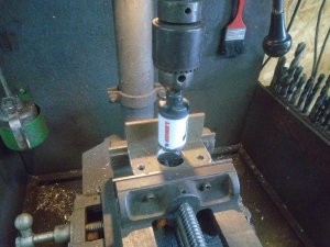
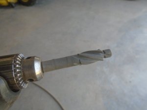
I'll start with this counter bore drill. It has a 3/8 inch pilot that will follow the 3/8 inch hole and keep the larger diameter cutting straight thru the housing.
This brings the front hole size out so it is only about .040 smaller then finish size.
DSC03780.JPG


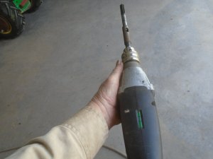
Then I'll use this 5/8 inch diameter reamer with the extension and a drill that has a level bubble on the top of it.
This makes it easier to ream the hole level and square with the housing.
DSC03781.JPG


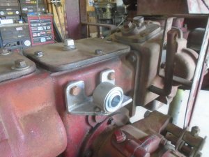
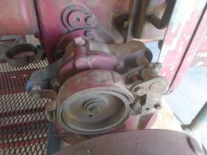
The brake assembly from the other side is now mounted on this side.
I drilled a 3/8 inch clearance hole thru a short 5/8 inch bolt and used it for the spacer for the rear hole.
The 3/8 inch bolt that fastened the front of the brake assembly in place had a 1/4 inch wide spacer between the bracket and the housing.
I cut the face of the 5/8 inch bolt head down to 1/4 inch thick so that bracket is still the correct distance out from the housing.

The operating lever for the brake is now in the front where there is plenty of room for the operating linkage.
DSC03784.JPG
 
The clutch on this garden tractor was operated by hand by pushing a lever forward to lock the clutch in drive position.
Pulling the lever back opened the clutch.
I want to have a foot pedal to operate the clutch but that will only pull the clutch arm back so I need a strong spring to pull the clutch arm forward to engage the clutch and keep it engaged.

This was the same problem that I had with converting the clutch on the John Deere crawler from hand operation to a foot pedal.
Just putting a spring on the clutch arm won't work because when the clutch pedal is pressed down, it is holding back all the pressure of the spring and my foot and leg would get tired really quick.
To solve that problem on the crawler, I made up a rotating bracket with a lever that rotated around until the spring was held back at almost top dead center of the rotation.
This then took almost all of the spring pressure off the foot pedal when the clutch was open.

I am going to make that same type of setup for this tractor.
First, I drill two mounting holes in a piece of angle iron and drill a clearance hole between them.

DSC03788.JPG


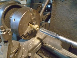
Then I machine out a piece of steel tube for the bearings to fit into.

DSC03787.JPG


This steel ring is welded to the angle iron and the bearings are pressed into it.
This assemble will bolt onto the side of the tractor behind the clutch arm.

DSC03789.JPG


Next I make up a little " U " shaped bracket that is drilled and tapped for a 5/16 shoulder bolt.

DSC03792.JPG


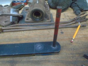
This piece is welded to a collar on one end of a 3/4 inch diameter steel shaft.

DSC03795.JPG


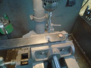
A 7/16 inch diameter reamer is used to finish the hole in this small steel bar.
A brass bushing with a 5/16 ID will be pressed into this hole.

DSC03794.JPG


The steel bar is attached to the bracket and it is heated up and bent down around the steel shaft.

DSC03796.JPG


This is mounted onto the bearing bracket and I mark the steel bar fort where I need to drill the hole in it to hold the spring.
You can see here that the large clearance hole was needed in the piece of angle iron so that this shaft can be slid in or out of the bushings.

DSC03797.JPG


The pivot finished bracket is bolted onto the side of the tractor and the spring is attached to it.
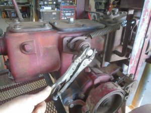
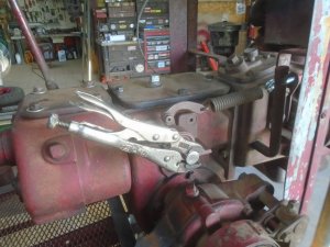
I had to use both hands to rotate the vice grip down and pull the spring back.
With the spring pulled all the way back to almost top dead center, the pressure on the vice grip is so slight that I can hold it down with just the tip of my thumb.

DSC03799.JPG


When I release the vice grip, it is rotated back up almost 5 inches.
The clutch arm on the tractor only needs to move about 1-3/4 inches so there will be plenty of spring pressure left on it to lock in drive position in and hold it in place.

DSC03800.JPG
 
The clutch operating lever is made up and slid onto the shaft of the spring lever.
Then I made up the clutch rod.
This is the position with the clutch open.

DSC03802.JPG


And with the clutch closed.

DSC03803.JPG


Another lever will be welded to this that the cable from the clutch pedal will connect too.
This will eventually get a hole drilled thru it and a split pin pressed into it to lock this lever onto the 3/4 inch shaft.
I don't want to do that though until after the clutch pedal is made and the cable attached and I make sure that everything is working properly.

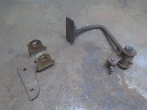
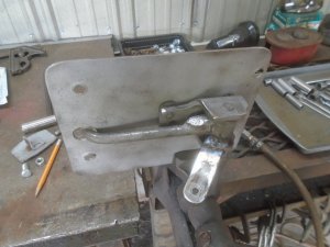
Scrounging thru my stuff, I found this bracket and and an old pedal off ... who knows what ?

DSC03804.JPG


I'm going to use a 5/8 inch diameter shoulder bolt for the pivot pin so I reamed the holes in the bracket out to 5/8.

DSC03808.JPG


Then I turned a 1/2-13 nut down part way.

DSC03807.JPG


This nut is then pressed into one of the holes in the bracket.

DSC03809.JPG


Now the shoulder bolt can be screwed into the bracket for the pivot pin.
I had to use the press to push the old pin out of the pedal.
That will get reamed out a little and a brass bushing will be installed in it.

DSC03811.JPG


I have some solid 13/16 inch diameter bearing bronze and I have drilled and reamed a piece of it out to fit the shoulder bolt.

DSC03813.JPG


The bronze bushing is pressed into the pedal and the pedal is assembled to the bracket.

DSC03815.JPG


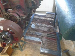
Here is where it will be located on the floor of the cart.

DSC03816.JPG
 
Was able to work on it a little bit after church this morning.
This is the start of the bracket to hold the cable.

DSC03817.JPG


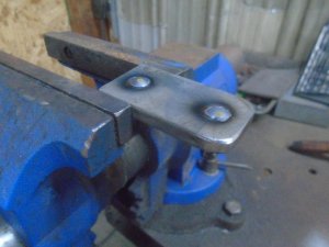
After drilling some mounting holes in it and bending up the tab on the end, I then welded a short piece of small diameter pipe to it.
The pipe is threaded on the inside to accept the adjuster on the cable housing.
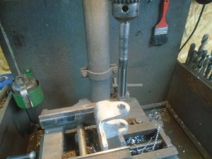
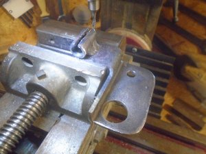
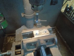
Here I'm milling a slot into it so the cable itself can be slipped into it and then the adjuster can be screwed into place.

DSC03818.JPG


The cable bracket is mounted to the side of the tractor, behind the brake band and with that in place, I can figure out how long the lower lever needs to be.
The lever is made up and welded to the pivot shaft and then this is drilled thru and a bolt is put thru to lock it onto the shaft.

With the cable connected, this is the position with the clutch open.

DSC03819.JPG


And this is the position with the clutch closed.

DSC03820.JPG
 
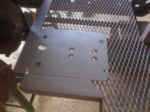
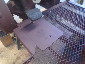
I made up a 1/8 inch thick steel mounting plate for attaching the clutch pedal bracket to the floor.

DSC03823.JPG


The plate is primed and fastened down on top of the floor.

DSC03824.JPG


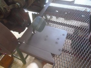
Then the clutch pedal bracket is bolted to it from underneath, sandwiching the floor grid metal between the steel plate and the pedal mounting bracket.

DSC03826.JPG


The cable is attached to the lever and this shows the good amount of ground clearance there is to the end of the cable lever.

DSC03832.JPG


A closer view of showing the mount that bolts to the underside of the floor for holding the cable housing.

DSC03827.JPG


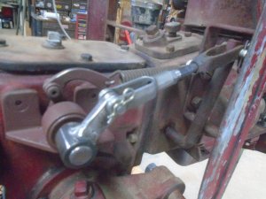
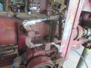
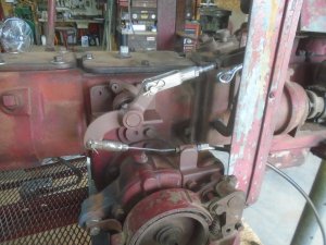
A view of the cable running from the clutch linkage on the right side of the engine and down to the pedal on the left side.

DSC03835.JPG


Looking at it from the side, you can see that the cable stays tucked in close to the tractor.

..... You may notice that this linkage looks different from the last photo that I had showed you. When I was making up the lever to weld onto the clutch pedal, the amount of cable movement wasn't working out to what I had figured out that it should be.
Going back over everything, I realized that I had switch the dimensions for the length of the top and bottom levers on the linkage on the side of the tractor.
The top lever was suppose to be the longer lever and I had made the bottom one the longest lever.
So I pulled that lever back off of the 3/4 shaft, flipped it end for end and put it back on the shaft. Now everything works right.

DSC03836.JPG


In normal position, the clutch lever on the engine is in the forward position with the clutch engaged.

DSC03833.JPG


Pushing the pedal down pulls the clutch lever back and opens the clutch.
When the pedal is released, the spring pulls the clutch lever back forward and engages the clutch.

DSC03834.JPG


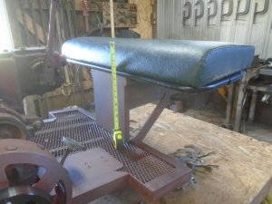
While I sitting on the tractor and working the clutch pedal, I realized that the seat feels a little low. So I checked the measurement of the top of the seat again and it is 15-1/2 inch .. just what the bus seat measured before I cut the frame apart.
Then is dawned on me that school bus seats are built for school children. Granted, at 5 foot 5 inch, I'm not considered a tall person by any means but I am still taller than most of the kids that ride school buses.
So .. I think I'm going to have to raise that seat a little.

DSC03831.JPG
 
Last edited:
I made a slight cosmetic change to the plate under the clutch pedal.
I decided to weld in the top of the bolts in the corners that fasten it to the floor grid.
This gives the plate a much smoother look.

DSC03867.JPG


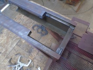
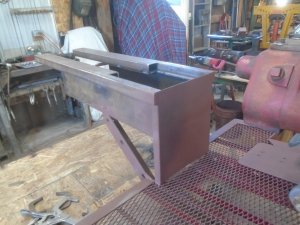
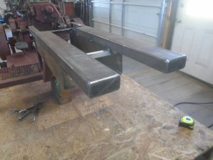
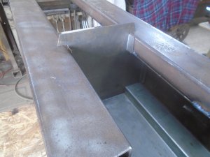
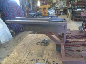
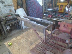
I welded two sections of rectangle steel tubing to the tractor frame to raise the seat up some.
These are long enough so they extend out past the end of the frame where the rear axle will be fastened on.
The section of trailer bed that will be attached behind the seat will rest on these longer rails.

DSC03870.JPG

DSC03864.JPG


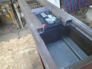
This cutout area under the seat will be boxed in for storage.
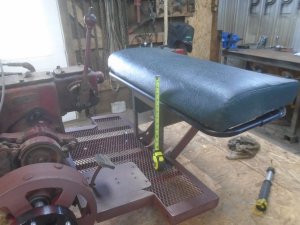
The battery will also be located under the bed just behind this storage area.

DSC03869.JPG


The area in front going down to the floor is closed in with a piece of metal.

DSC03868.JPG


The back ends of the tubes are also closed in.

DSC03865.JPG


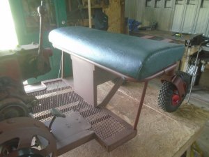
This raises the height of the seat up to about 17-1/2 inch and it feels much more comfortable now.

DSC03871.JPG
 
Neat. I like how you figured that clutch pedal operation. So that one spring has enough pull to disengage the clutch from the almost over centre arm. Great idea. And easy to hold. I’ll have to show my son this.

Noel
 
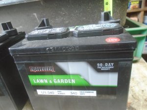
The overall height of the battery is about 7-3/8 inches.

DSC03875.JPG


The clearance height of the storage space under the seat and under the bed of the trailer box is a little over 6 inches.

DSC03876.JPG


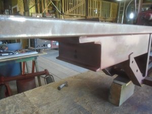
The underside of the trailer box has two ribs welded to it and with these ribs resting on the top of the frame, it will give me an added 1 inch of clearance.
DSC03877.JPG


That is a total of only about 7 inches clearance so I need to lower the bottom of the storage area to gain another inch of clearance.
I'm going to show you a step by step process of forming this panel for the floor of the storage space under the seat and under the bed of the trailer box.

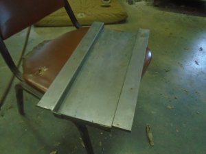
I figure out how wide and long the panel needs to be and cut that out.
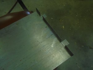
Then I mark where I need to make the bends in it and cut 1 inch long slits in one end of it at those bend marks ( this doesn't really show up very well )

DSC03878.JPG


I bend up 1 inch of the end of the panel where the slits are.
DSC03879.JPG


And I bend two tabs back down flat.
DSC03880.JPG


My home made sheet metal brake that I have will let me make a bend with an end tab pointing up but I can't make a bed with the end tab pointing down.
Also, I want to make two bends that will be 1 inch apart where the flat tabs are and they need to bend in opposite directions to form a " Z ".
The closest that I can make two opposite bends on my brake is 3 inches. Luckily, my son has the equipment to do these kind of bends.

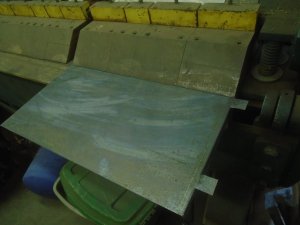
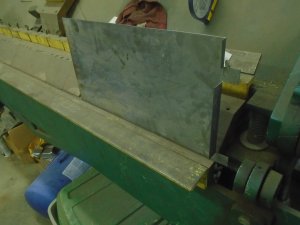
First I set the panel up in his big brake with the end tab pointing down.

DSC03881.JPG


And I bend the panel up at 90 degrees.

DSC03882.JPG


I do this to the other side of the panel so both sides are bent up and the end tabs are bent out.

DSC03883.JPG
 
Last edited:
The panel is set up in another brake that will make close bends at opposite directions.

DSC03884.JPG


And I make that opposite bend in it.

DSC03885.JPG


Then I turn the panel around to make the bend on the other side.

DSC03886.JPG


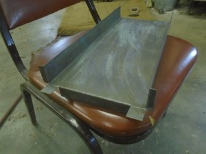
The panel now has the center area stepped down 1 inch.

DSC03887.JPG


The two tabs that were flattened out earlier are now bent back over the end.

DSC03888.JPG


I'm done with what I have to do with the panel here.

DSC03889.JPG


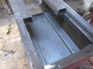
The panel is set into the frame.

DSC03890.JPG


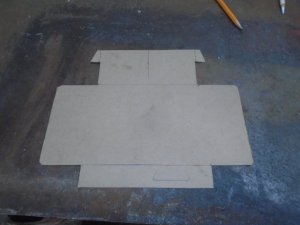
I make up a pattern for the end panel out of cardboard.

DSC03895.JPG


Then I cut this panel out of sheet metal and set it in place.

DSC03893.JPG


As you can see, the battery slides back under the bed and has about 3/4 inch clearance between it and the underside of the bed.
All that is left is to weld this in place.
I'll make up a piece of wood that fits onto the top of the battery that will keep it from bouncing up and touching the underside of the bed.
There will be another end panel that can be screwed in place in front of the battery to separate it from the storage area.

DSC03894.JPG
 
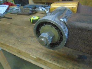
I don't know what type of bearings these casters had originally when they were on a zero turn mower.
I wanted tapered roller bearings on this cart and I also wanted a grease seal on them.
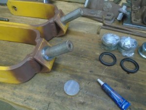
The bearings and seals arrived in the mail so I can now put the rear axle together.

First thing was to machine a ring out of stainless steel for the grease seal to ride on.
The ring is slid down on the pivot shaft and I used Lock-tight to secure it in place.
The other un-machined piece of stainless is sitting on the bench.

DSC03897.JPG


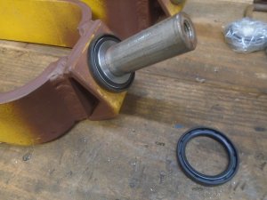
The seal fits down over this stainless ring.

DSC03909.JPG


This is how the bottom bearing will sit down on top of the ring with the seal underneath it.

DSC03898.JPG


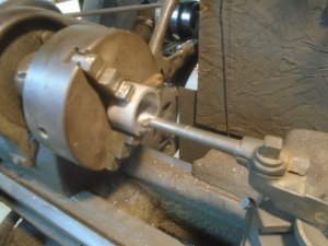
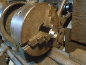
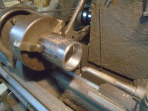
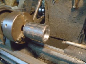
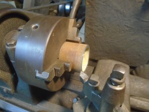
I chuck up a piece of pipe on the outside and then I bore out one end for the bearing and the seal to fit into.
These will be the pivot housings that will be welded onto the ends of the axle to hold the casters.
The outside diameter of the seal is just a little larger then the bearings.
You can see that the bore is a little larger for the first 1/4 inch where the seal will fit into it.

DSC03899.JPG


The pipe is turned around and gripped by the inside bore this time to turn out the other end.
This way both bores are in line with each other.

DSC03900.JPG


There isn't much lip at the end of the bore for the bearing race to fit up against.

DSC03901.JPG


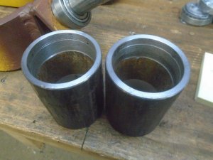
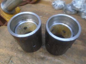
Another piece of pipe is faced off on both ends to form a spacer between the upper and lower bearing races.

DSC03902.JPG


These are placed inside the other pieces of pipe so there is now a wide lip for the end of the bearing races to fit up against.
These pipes are drilled and tapped thru in four places and hardened 5/16-18 set screws and threaded into both pieces of pipe.
These set screws will hold the spacer in place.

DSC03904.JPG


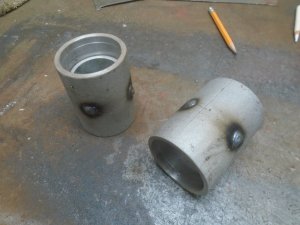
The pivot housings are sand blasted and the outside ends of the set screws are welded over.

DSC03906.JPG


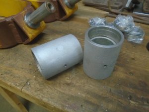
The welds are ground down and a hole is drilled and tapped into each housing for a grease fitting to be installed.

DSC03907.JPG
 
The rear axle is set up in the mill to cut a radius on the ends to fit the bearing housings.

DSC03911.JPG


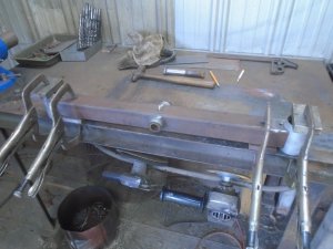
The axle and bearing housings are clamped together on the bench for welding.

DSC03912.JPG


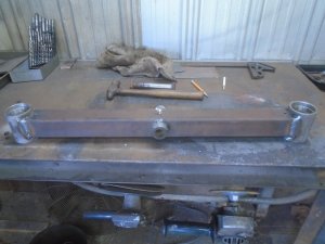
The welding is completed and the axle is ready to assemble the bearings and seals.

DSC03913.JPG


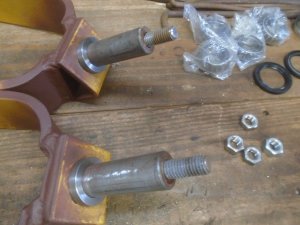
Originally the pivot shafts on the casters had a washer and bolt that screwed down tight to the top of the shaft.
I screwed a piece 1/2 inch threaded rod into the ends of the pivot shafts and used Lock tight to secure them in place.
Using a washer and 1/2 inch nut screwed down on top of the bearing will allow me to be able to adjust the tension on the bearings.
Then I can use a lock nut on top of the first nut to keep them secured.

DSC03914.JPG


The casters are assembled to the axle and they are greased until it starts coming out from the top bearing.

DSC03915.JPG


Then the caps are put on top of the bearing housings.

DSC03916.JPG


It's time to prime the axle.

DSC03918.JPG


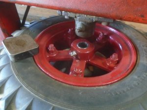
These wheels would most likely have had bronze bushings pressed into the hubs but I decided to go with roller bearings instead.

DSC03917.JPG


I had to machined spacers to fit between the wheel hub and the caster forks and I got one wheel assembled before I quit working in the garage today.

DSC03919.JPG

DSC03920.JPG
 
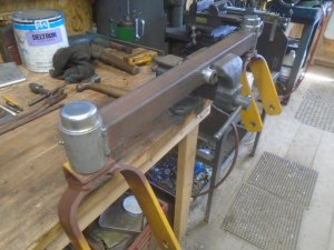
Working on a piece of channel iron to go across the back end for the rear axle to fasten to.
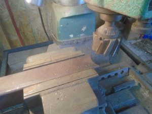
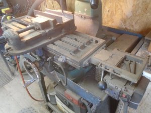
I need to cut about 3/4 inch off one side and I'm doing that up on the mill and cutting 1/16 inch at each pass.
I'm sure glad that I have power feed on the mill table for jobs like this.

DSC03922.JPG


This piece is welded between the frame rails.
This it the front support for the rear axle and the hole is already drilled and tapped for the center pivot bolt.

DSC03923.JPG


The back support for the axle is made out of 3/8 thick steel and welded in place.

DSC03927.JPG


The axle is sandwiched in between these two mounts.

DSC03928.JPG


Here's how the wheels will be positioned when moving forward.

DSC03924.JPG


And when moving backward.

DSC03925.JPG


The width of the rear wheels is about the same as the width of the original tractor wheels.

DSC03926.JPG


With the tractor now resting on it's rear wheels, the jack stand that was supporting the front of tractor can now be removed.

DSC03929.JPG
 
The seat frame is welded to the top of the frame rails.

DSC03930.JPG


The center is cut out of the two bars at the back of the frame for clearance to slide the battery in place.

DSC03932.JPG


I welded in two 3/4 inch diameter rods going down to the frame of the floor to give extra support for the seat frame.

DSC03931.JPG


I cut out two panels out of 1/16 inch thick sheet steel and primed one side.

DSC03933.JPG


These are welded in place under the seat frame.
This gives me two narrow storage spaces for wrenches, rags, magazines, etc.

DSC03934.JPG

DSC03935.JPG


There are two notches in the front edge of these panels for clearance for the brackets that fit around the seat frame and bolt to the underside of the seat cushion.
These allow the seat to be tilted forward and the clearance notches keep the seat cushion from moving sideways.
I only have two brackets holding the seat right now but when everything is finished, there will be four brackets bolted to the seat cushion.

DSC03937.JPG


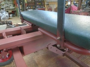
Here's how it looks with the seat cushion in place.

DSC03936.JPG
 
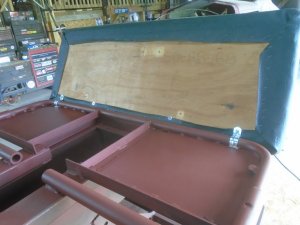
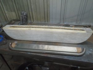
The backrest on the school bus seat is really tall and about 4 inches thick so I'm only going to use the top portion of it for the backrest for the cart.
This it the part of the padding for the backrest that I'm going to use and the top portion of the metal frame that goes with it.

DSC03938.JPG


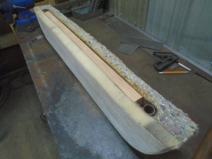
I attached a piece of wood to the metal frame and this fits into the slot in the center of the padding.
I'll trim the cover back and it will be folded over and stapled to the wood strip on the bottom of the backrest.

DSC03940.JPG


I'm going to use two pieces of 1-3/4" x 3/8" metal strip to support the backrest.
These will be welded to the metal inside the backrest and I want to make them so they will bolt onto the the back of the seat frame.
I've drilled two 3/8 inch clearance holes in each of the metal support strips.
Here I'm using a center punch to mark where the first hole will be in the short metal piece that will be the mount for the backrest.

DSC03943.JPG


Once that first hole is drilled and tapped in the mounting piece, then I bolt the support strip to it and drill a center point into the mounting piece thru the other hole in the support strip.
This is the easiest way that I have found to make sure that all the holes line up in both pieces.

DSC03941.JPG


Then I drill and tap that hole in the short mounting piece.

DSC03942.JPG


I cut the threaded part off some 3/8 bolts and screw these into the mounting pieces for threaded studs.
Then I weld them on the back side to lock the threaded studs in place.

DSC03944.JPG


These mounting pieces are bolted onto the support strips and the top of the strips are then welded onto the metal part of the backrest.
This is set in place on the cart and the bottom ends of the support strips are clamped in place to the back of the seat frame.

DSC03945.JPG


The short mounting pieces are then welded to the seat frame.

DSC03947.JPG


They are set so there is a little clearance between the backrest support strips and the back of the seat cushion.
You can see here that instead of having the 4 inch thick backrest between the back of the seat cushion and the front of the trailer box, I now will only have the thin 3/8 inch thick support strips.

DSC03948.JPG


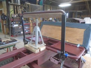
Here is the height of the backrest support.
The bottom of the padded backrest will be a few inches above the top of the trailer box that will be mounted behind it.
With the backrest being bolted on, I can take it off, paint it and then put the padding and upholstery on it before I bolt it back onto the cart.

DSC03946.JPG
 
Last edited:
Back
Top