
You are using an out of date browser. It may not display this or other websites correctly.
You should upgrade or use an alternative browser.
You should upgrade or use an alternative browser.
Winter project
- Thread starter jdcrawler
- Start date


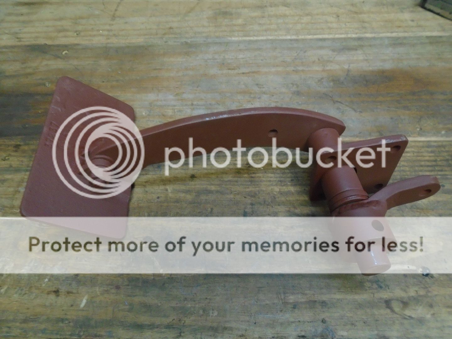
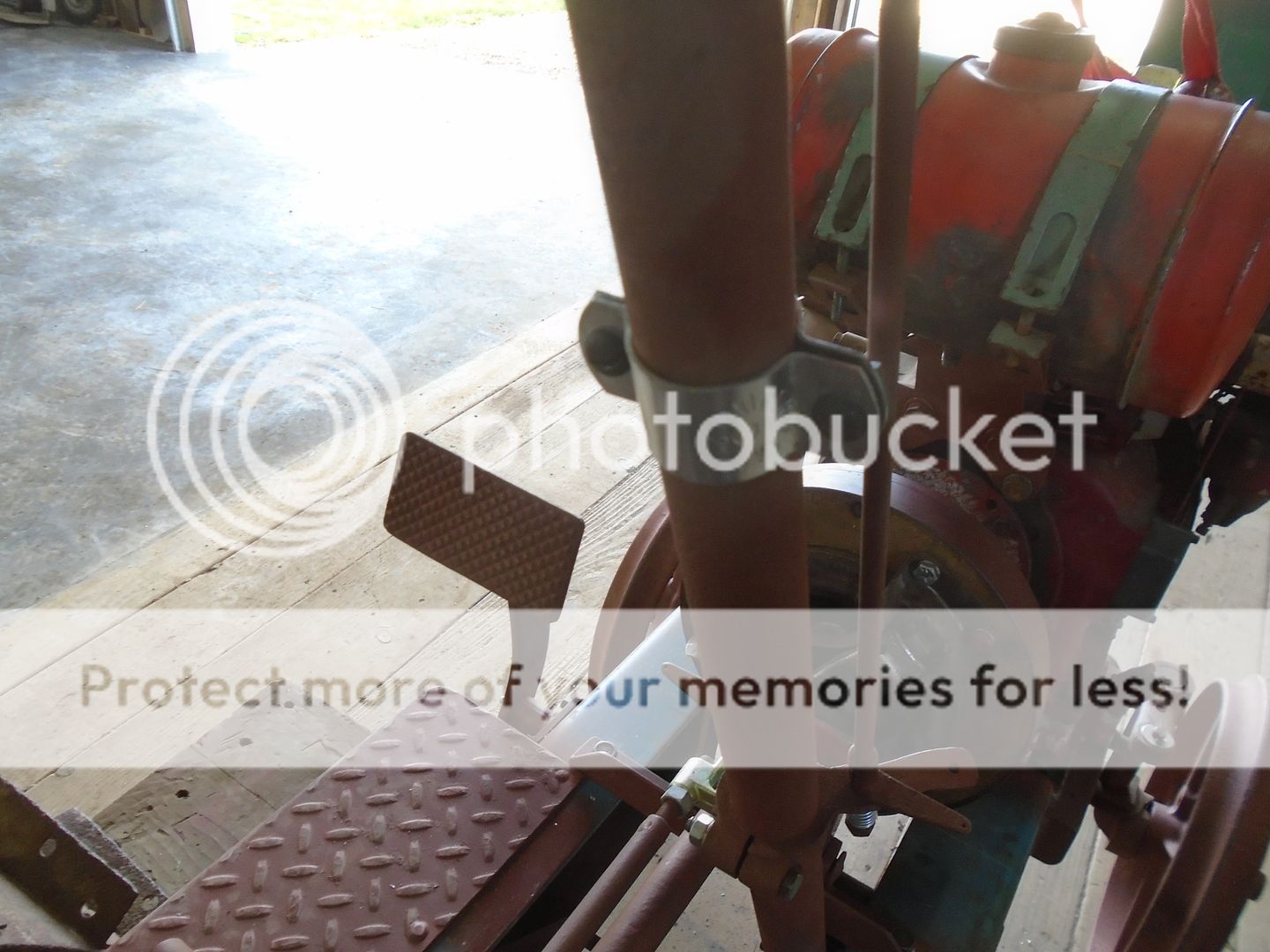
You do really nice work.I have this old cast iron pedal that I'm going to use for the clutch pedal.
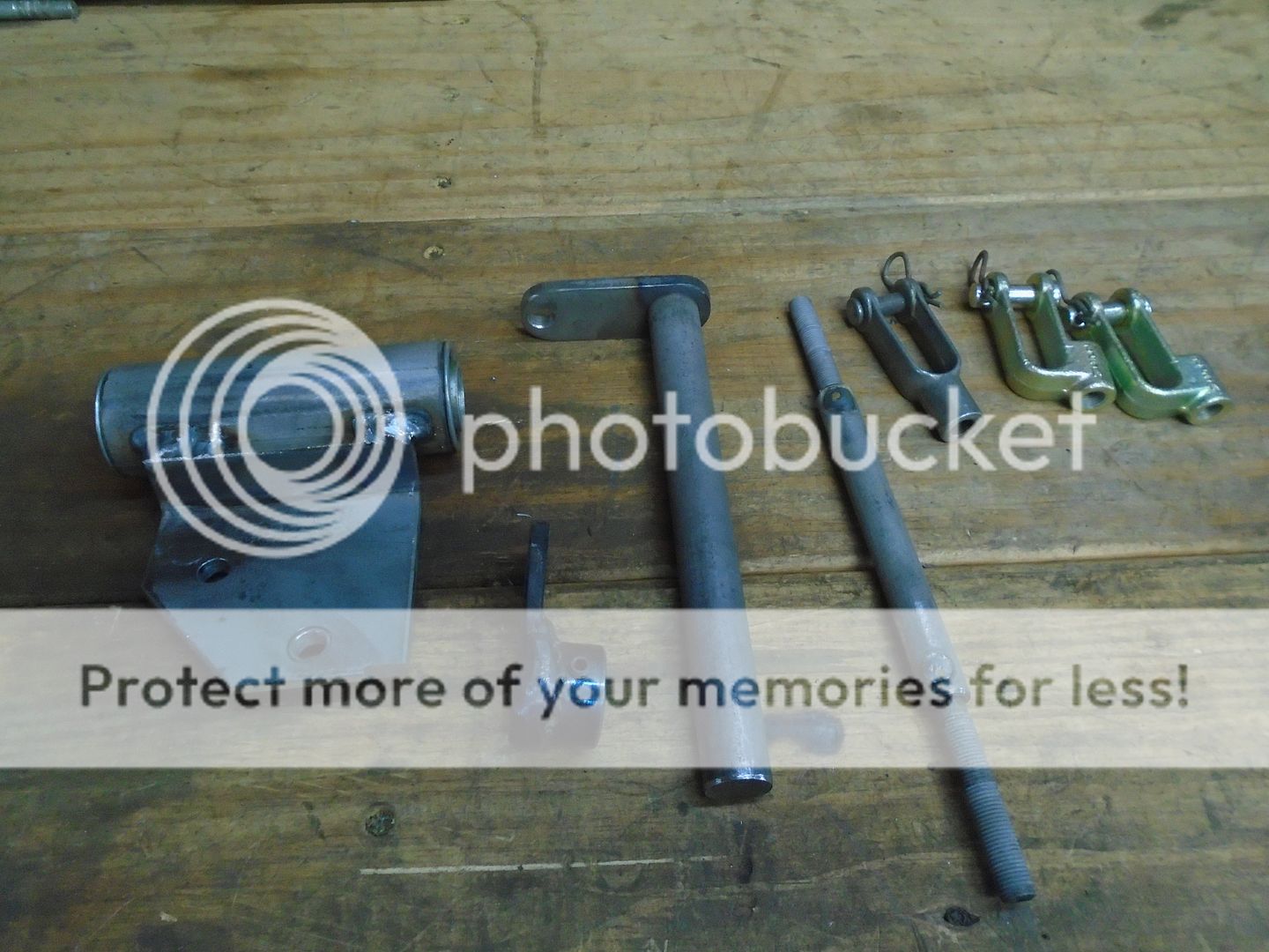
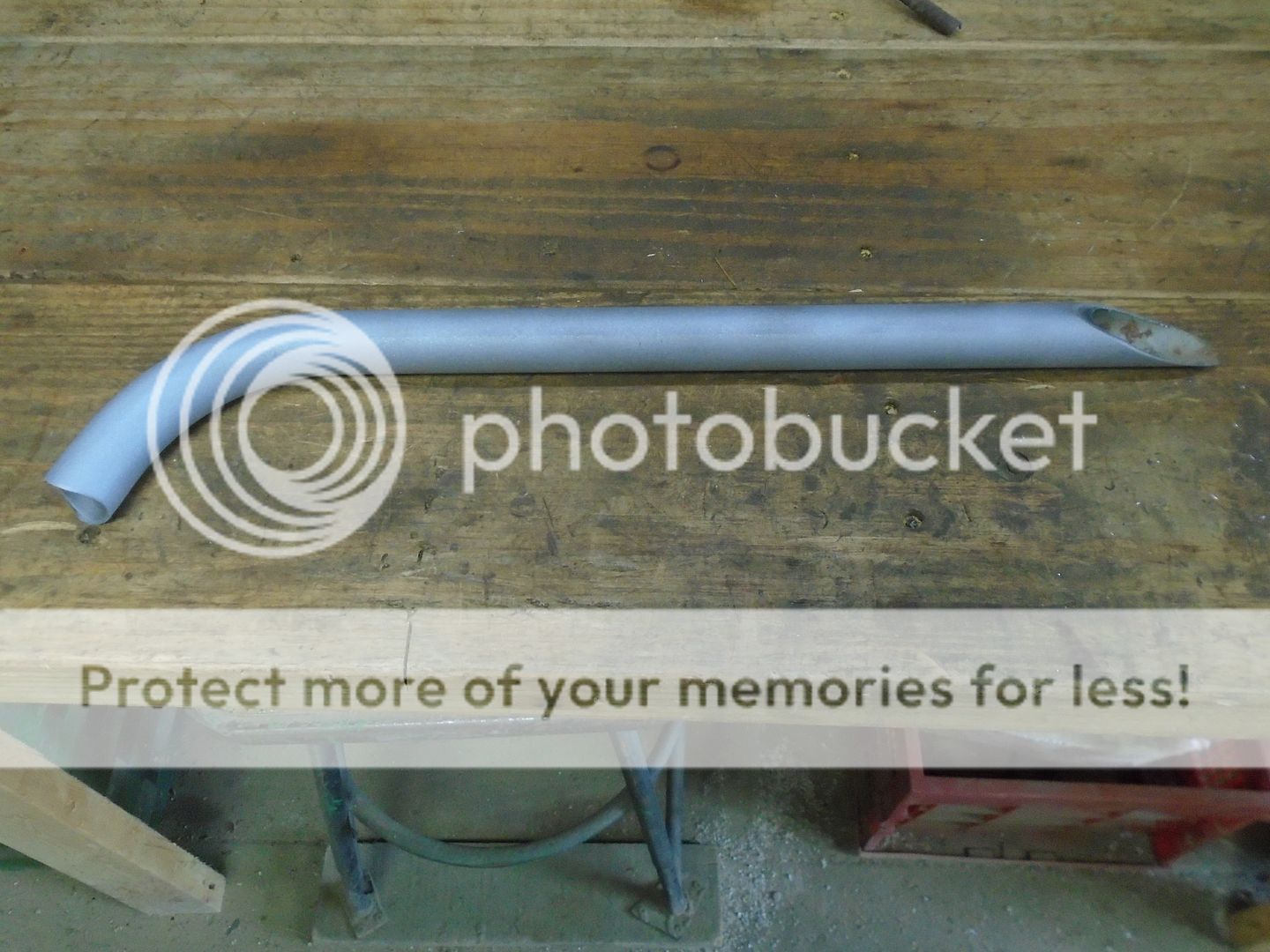
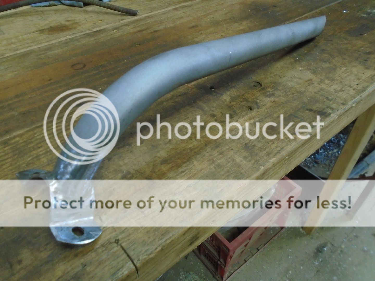
Here are the parts that I have made up that will be the clutch pedal assembly.
This is all of the parts put together.


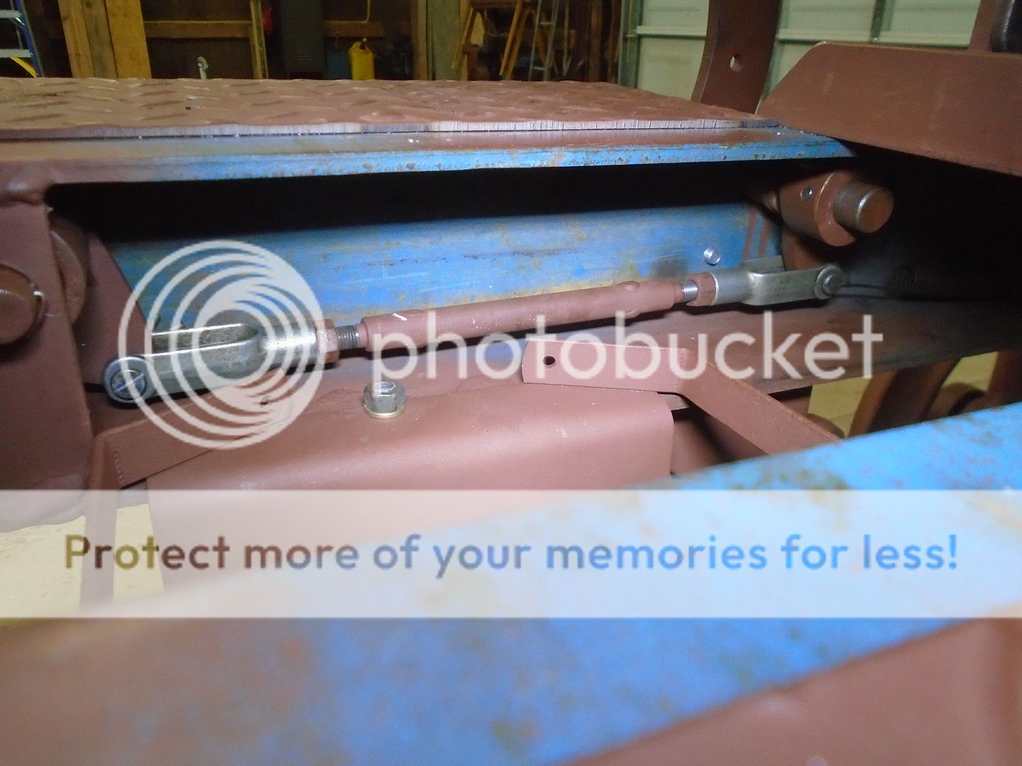
These are the parts that I have made up for the clutch linkage so far.
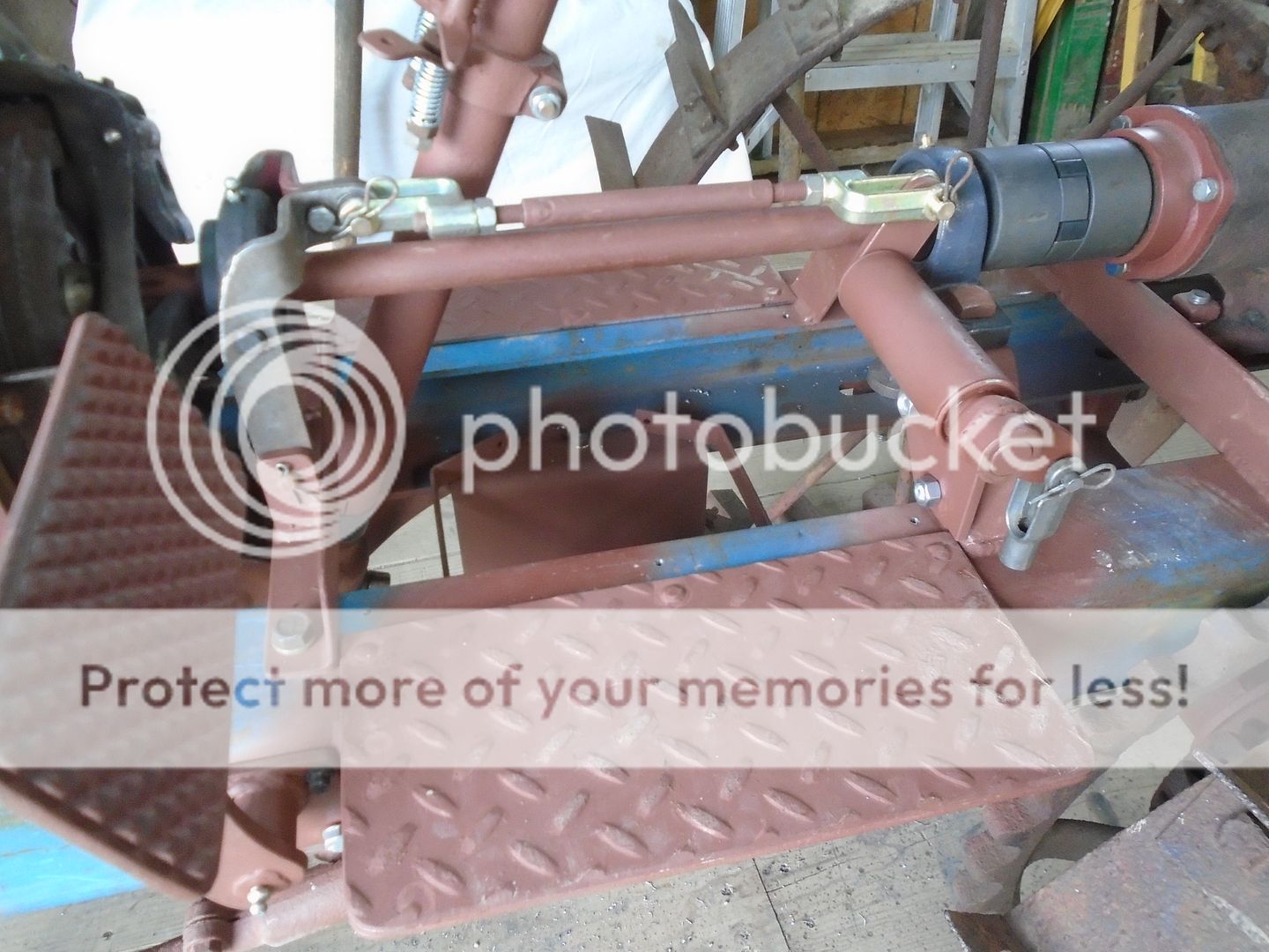
This is the part of the linkage that will attach to the top of the throw out bearing and run along side the driveshaft.
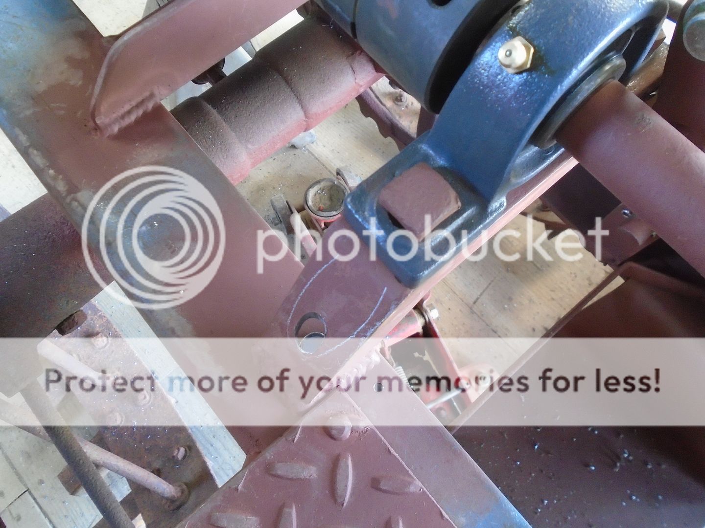
Here is how they fit on the tractor.
There will be a hole drilled in the top of the frame rail for the linkage from the clutch pedal to come up thru and attach to the gray colored clevis.


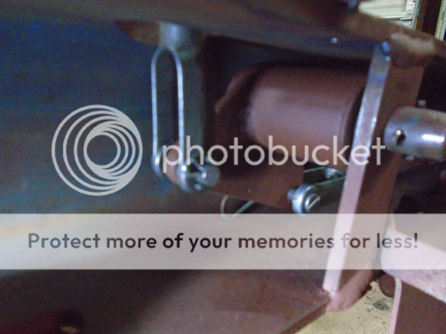
Just curious Ray, and maybe I missed the answer to my question but.....being there's no trans tube for the throw out bearing to slide on, what keeps the throw out bearing from tilting due to the space between it and the drive shaft? My apologies for asking if you've already addressed this.
Just curious Ray, and maybe I missed the answer to my question but.....being there's no trans tube for the throw out bearing to slide on, what keeps the throw out bearing from tilting due to the space between it and the drive shaft? My apologies for asking if you've already addressed this.
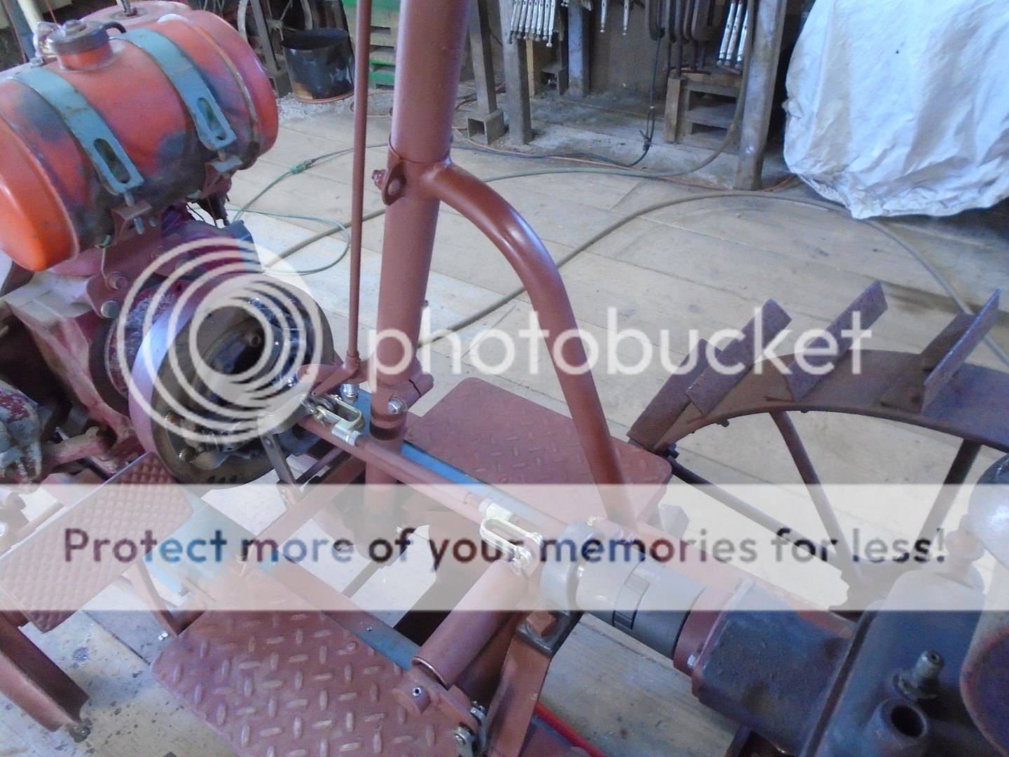
Look closer at the last two photos and you will see that the throw out bearing has a pin on each side that holds it in place on the bracket.
Looking good it maybe the picture but looks like its going to be a tight squeeze to get the battery in place, I like the clutch linkage setup
It's just how the photos look .. the battery slides in and out between the frame and the drive shaft without any problem.
I figured it had to be the picture but I have do things like that really proud of how I did something then go to finish up and oops on to plan BIt's just how the photos look .. the battery slides in and out between the frame and the drive shaft without any problem.
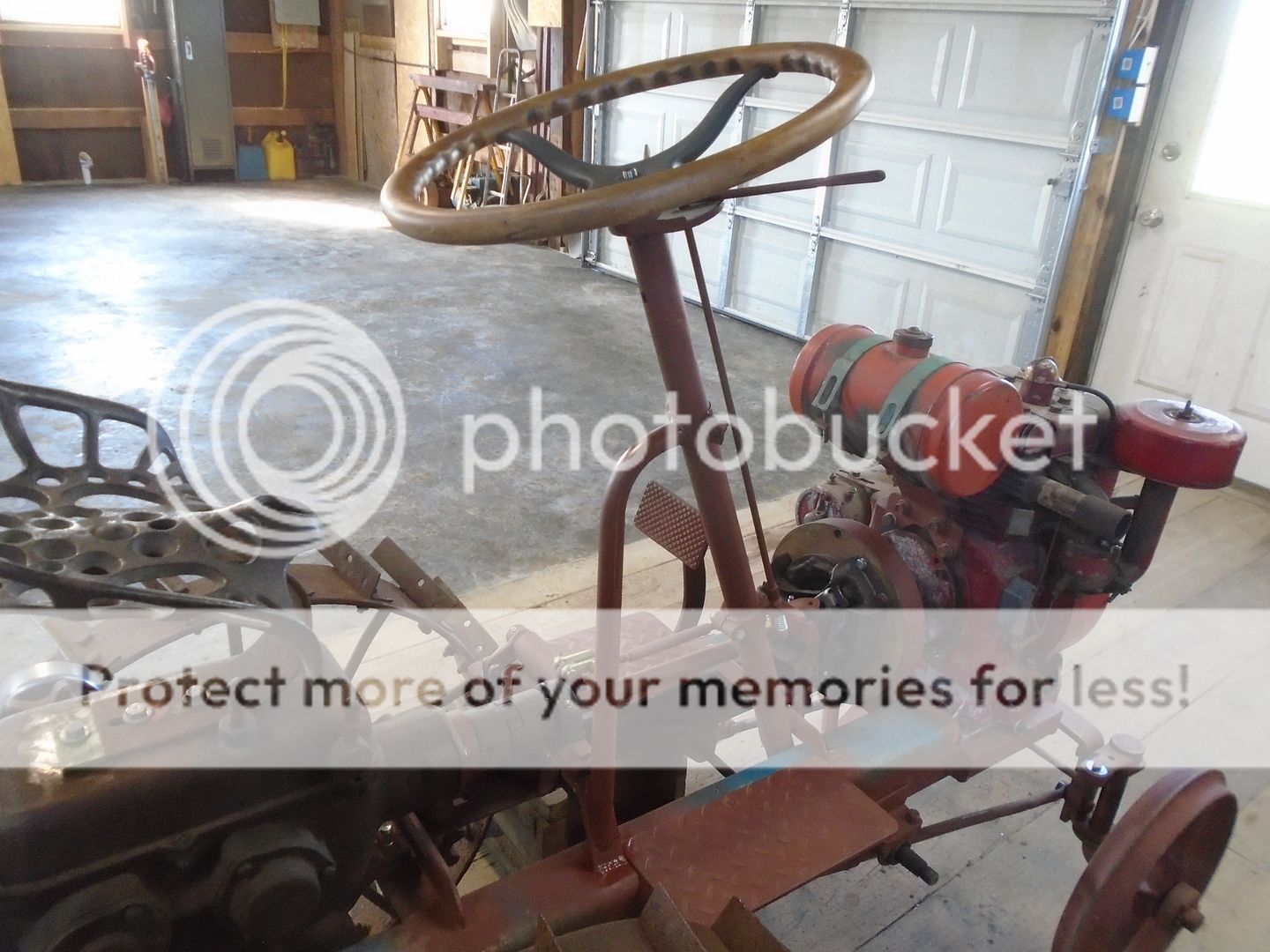
I now have a working clutch.
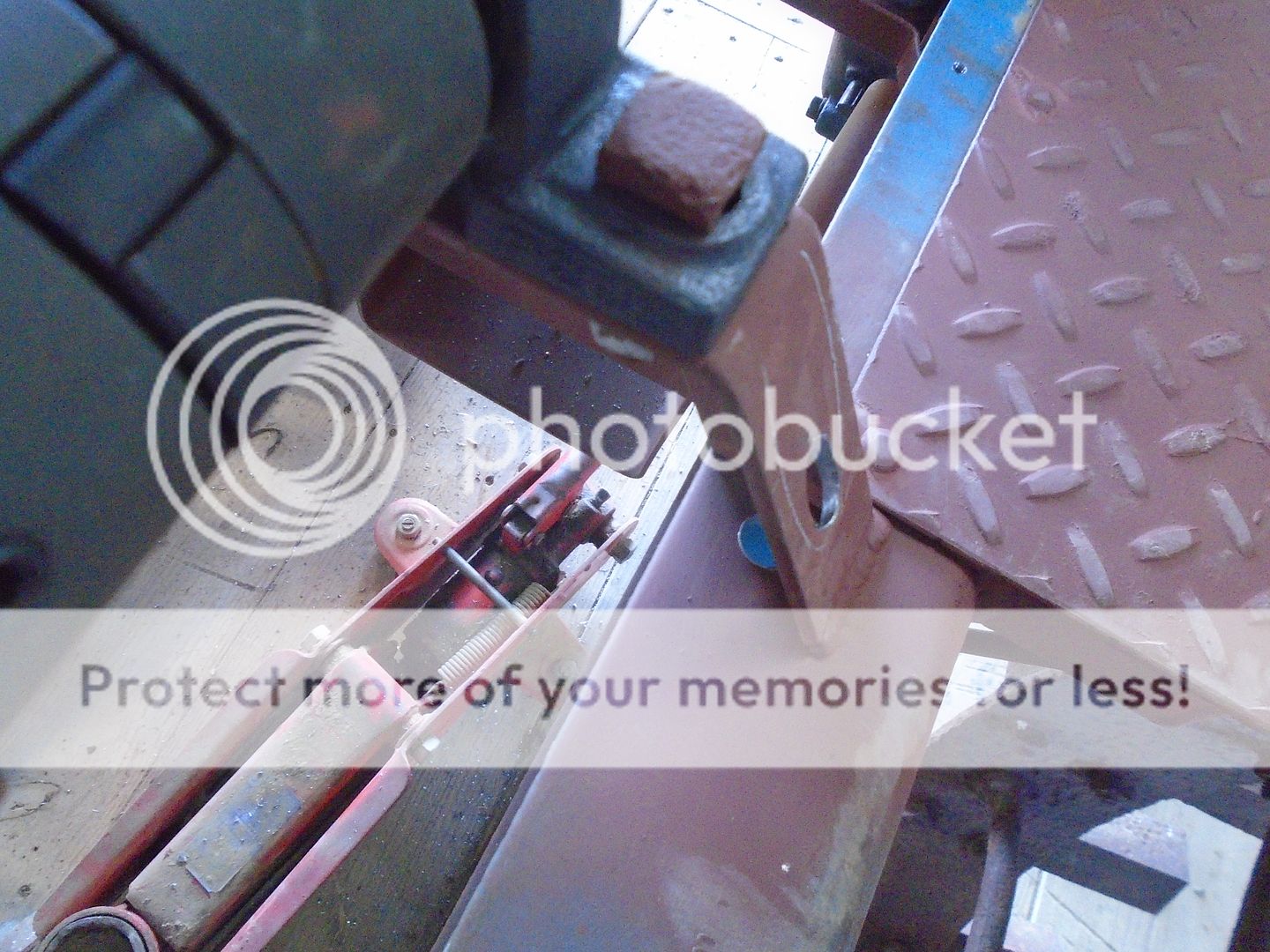
This is how the clutch pedal and linkage looks from the side.
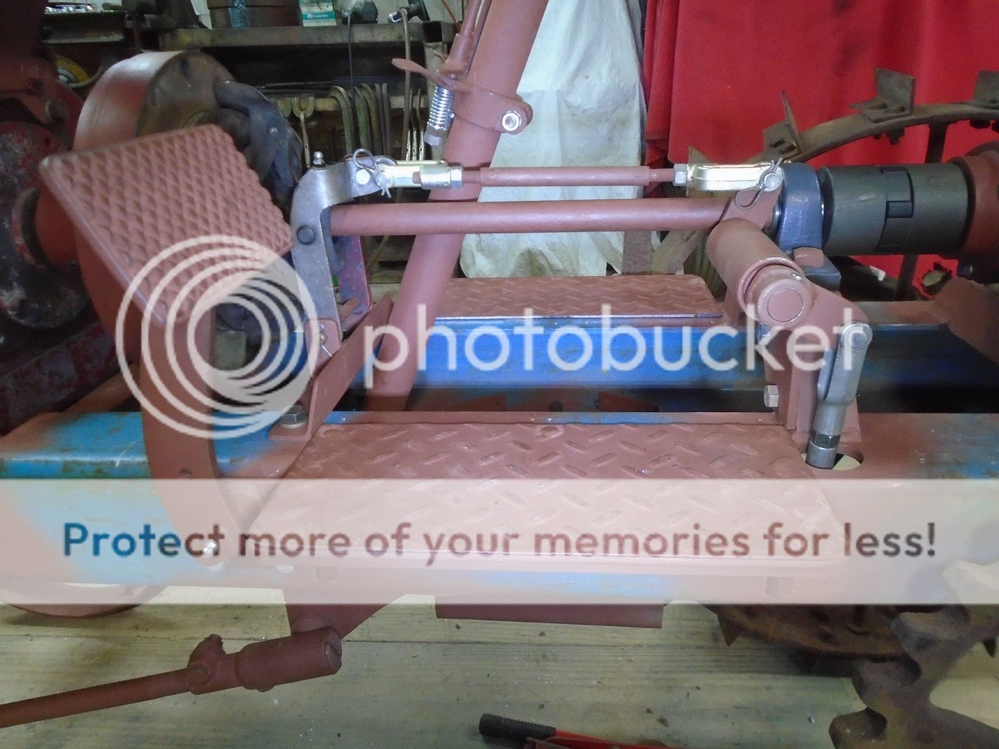
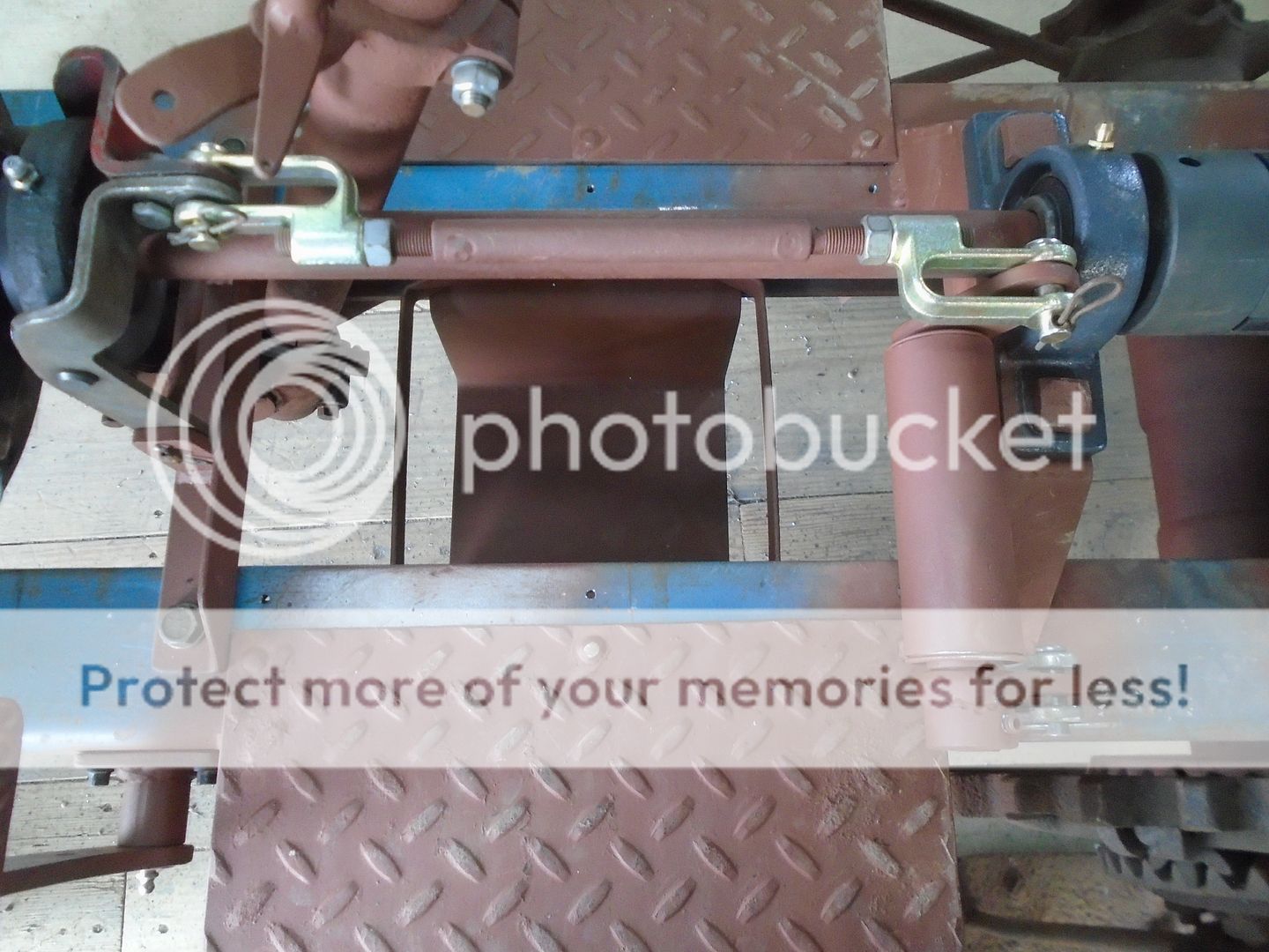
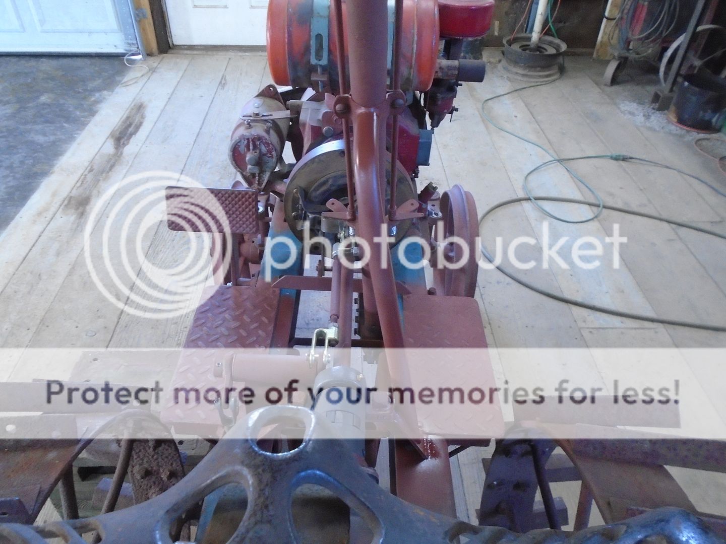
And from the top.
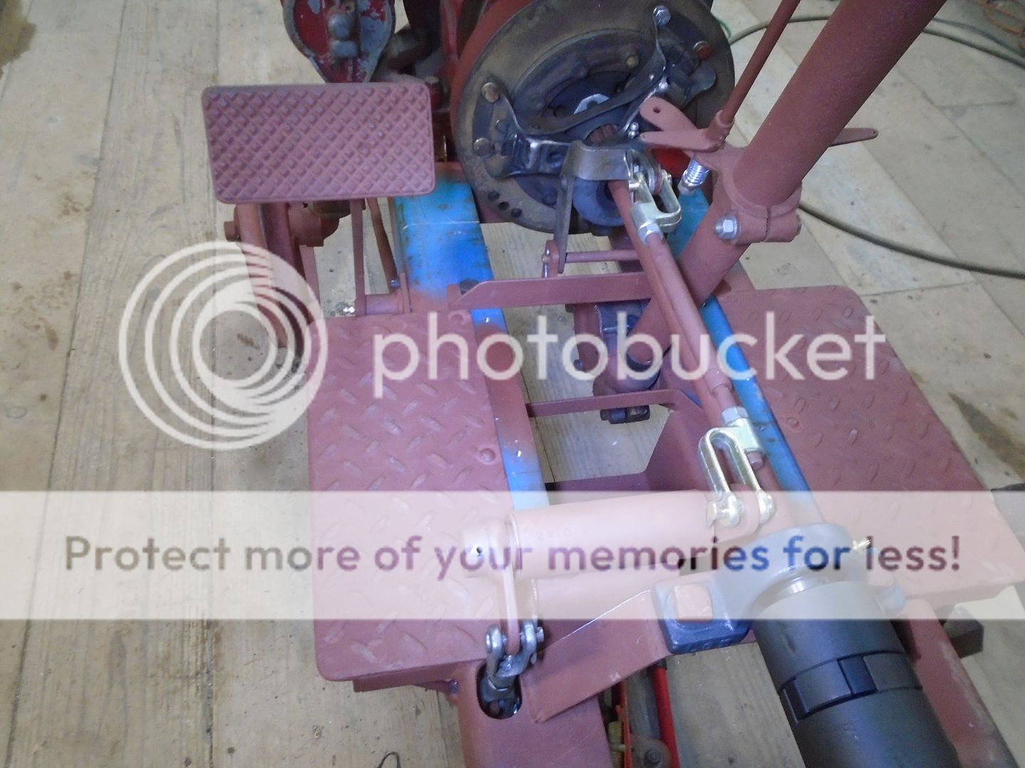
On the inside of the frame, this rod pushes back horizontally when the clutch pedal is pressed down.
This lever changes the horizontal motion to a vertical motion pushing up thru the frame.
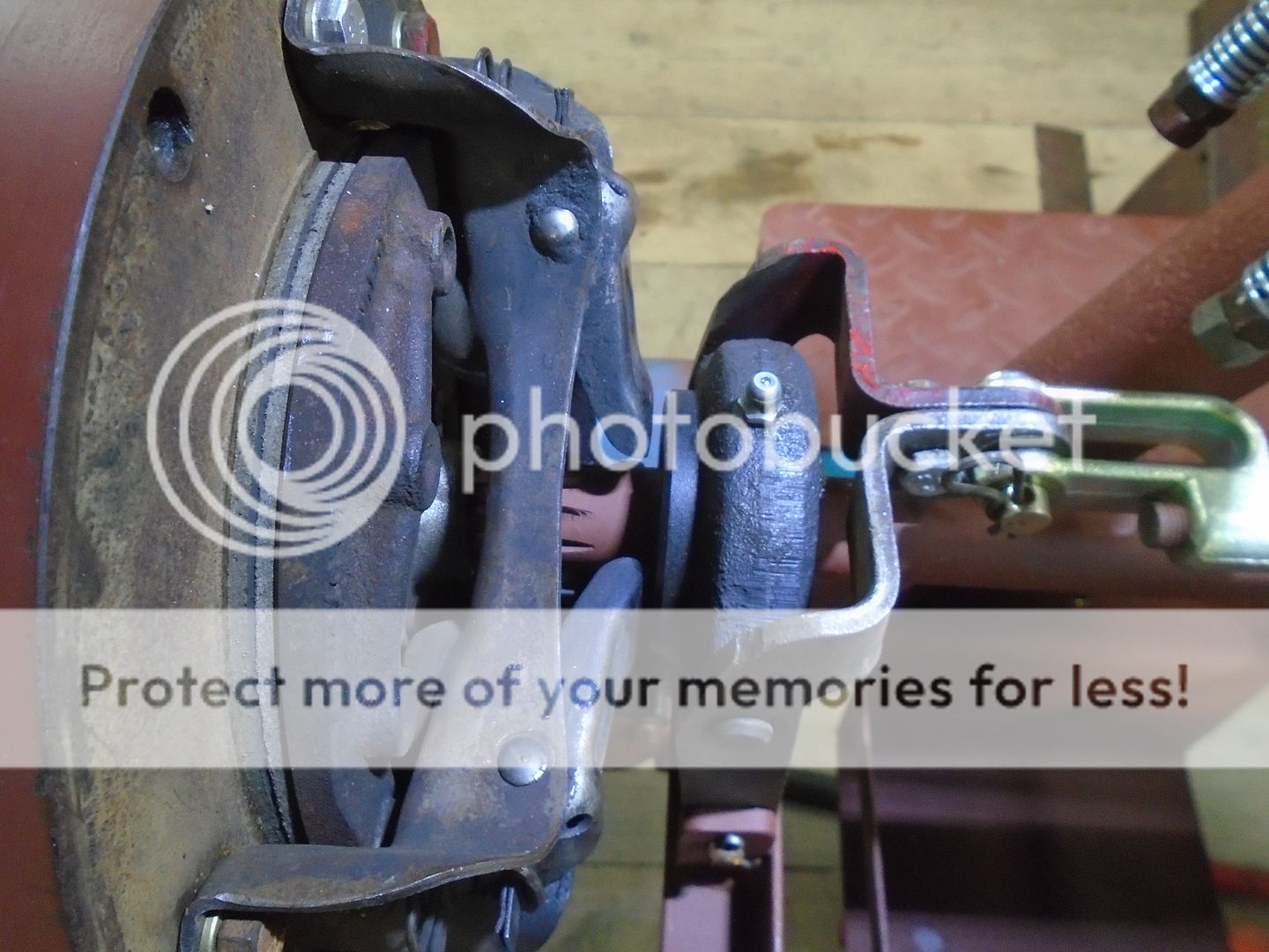
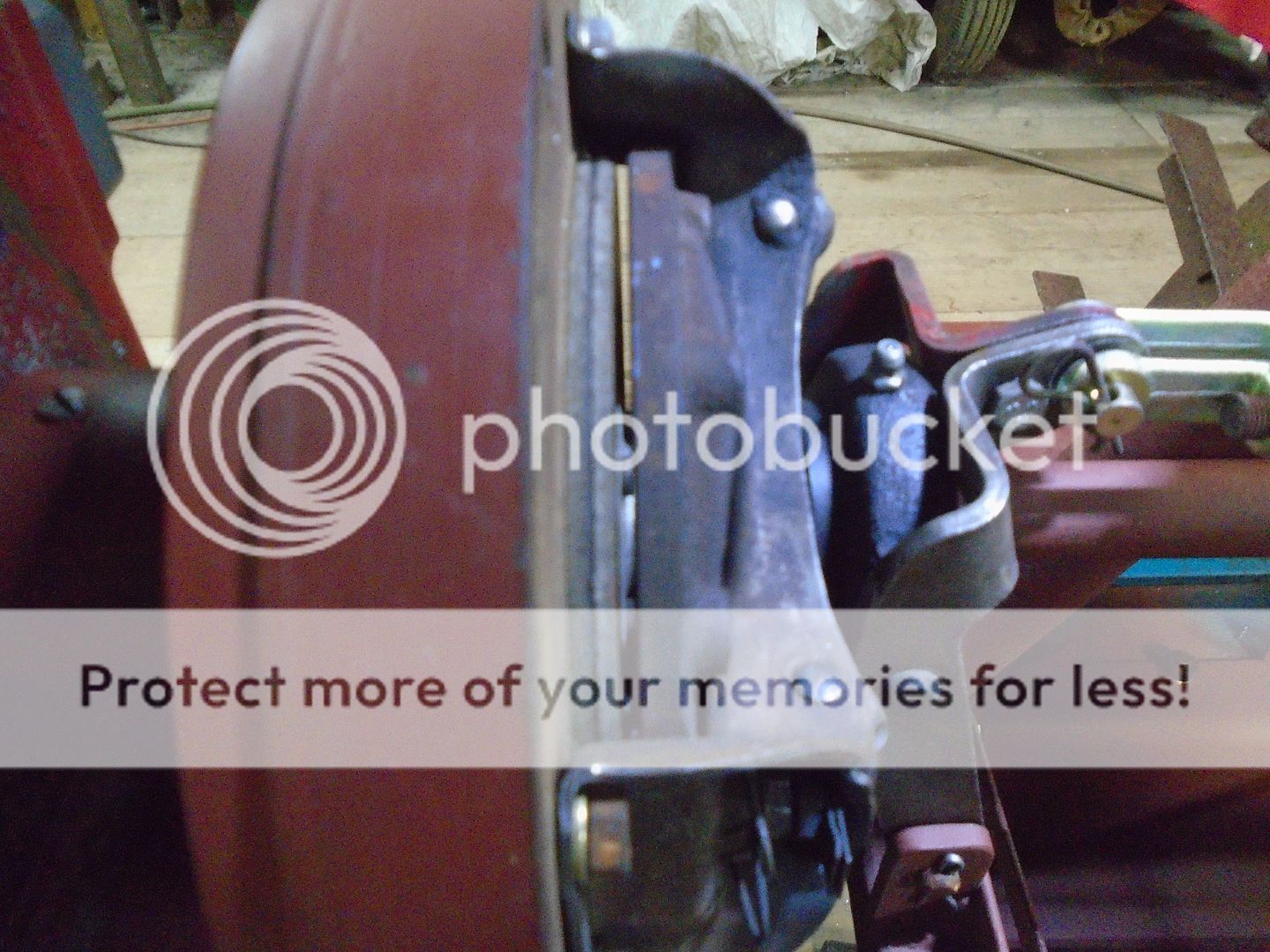
Where that vertical motion is changed again to a horizontal motion that pushes forward to push the throw out bearing against the arms of the pressure plate.
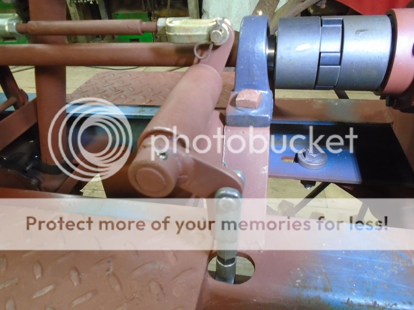
The throw out bearing is held back a little ways from the pressure plate arms when it is disengaged.
The pedal and linkage works easy enough so that the pedal can be pushed down by hand to open the pressure plate.
This is how the clutch pedal and linkage looks from the side.

And from the top.

On the inside of the frame, this rod pushes back horizontally when the clutch pedal is pressed down.

This lever changes the horizontal motion to a vertical motion pushing up thru the frame.

Where that vertical motion is changed again to a horizontal motion that pushes forward to push the throw out bearing against the arms of the pressure plate.

The throw out bearing is held back a little ways from the pressure plate arms when it is disengaged.

The pedal and linkage works easy enough so that the pedal can be pushed down by hand to open the pressure plate.

I found a strap clamp that fits perfectly around the steering column so I can start working on the support for it.
This is the piece that I made up for supporting the steering column.
One half of the strap clamp is welded to one end of it.
The other end is going to be welded to this pillow block bearing mount.
I'm going to want to have an electrical box on this tractor to hold the amp gauge and the switches and the most logical place to mount it would be on the steering column support tube.
In preparation for doing that, I have drilled a hole in the bearing mount so the wiring can be hidden by running it up the inside of the tube.
The hole is also drilled down thru the top of the frame rail.
The top of the support tube is fastened to the steering column and the bottom is welded in place.

This is the piece that I made up for supporting the steering column.

One half of the strap clamp is welded to one end of it.

The other end is going to be welded to this pillow block bearing mount.
I'm going to want to have an electrical box on this tractor to hold the amp gauge and the switches and the most logical place to mount it would be on the steering column support tube.
In preparation for doing that, I have drilled a hole in the bearing mount so the wiring can be hidden by running it up the inside of the tube.

The hole is also drilled down thru the top of the frame rail.

The top of the support tube is fastened to the steering column and the bottom is welded in place.


I love how this build looks like something that came out of a factory a 100 years ago.
Going off subject here .... I wasn't going to post anything on this but I changed my mind at the last minuet.
Looking thru my photos, this is the only one that I could find of my JD mower.
The rear wheel weights are old Bolens Ridemaster weights and I took them off to use on one of my Ridemasters.

With the weather getting warmer, it is time to start mowing again and there are areas where I need rear weights on the mower.
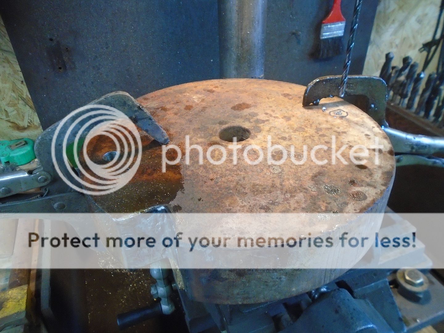
Some time ago I had picked up a pair of 10 inch diameter by 2 inch thick steel cutouts.
I set one of the Ridemaster weights on top of them and marked where the two bolt holes go and where the notch for the valve stem needs to be.
Then I used the torch to cut out the valve stem notch.
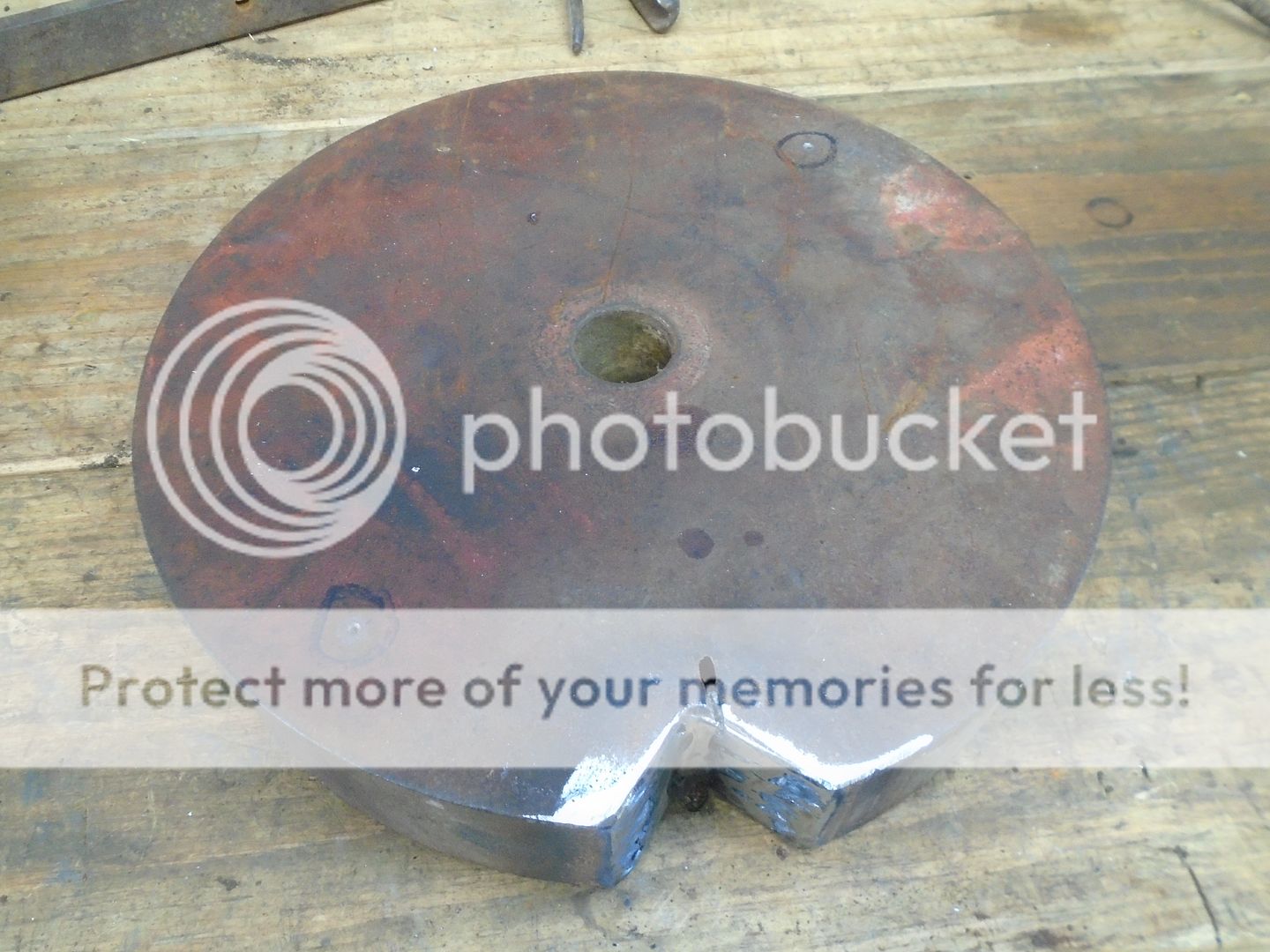
And I put them up on the drill press to drill the holes out to 17/32 ( .03 over the size of the half inch bolts ).
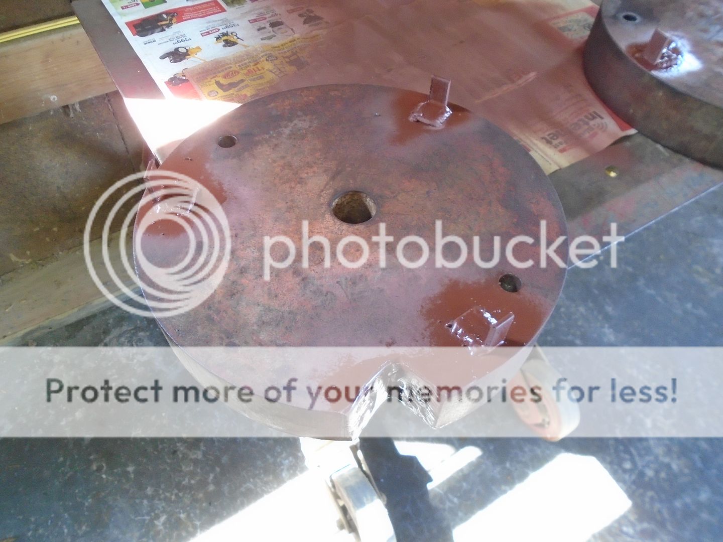
I'm welding three small pieces of angle iron on the inside of each weight to center them in the wheel opening so they don't flop around.
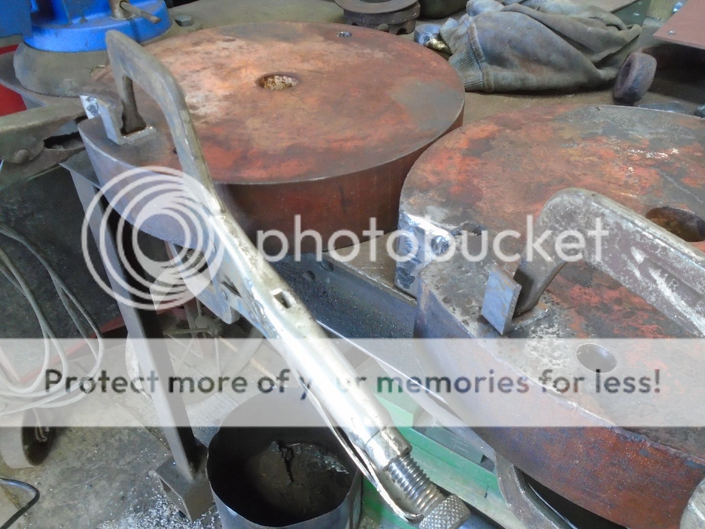
Here is how they look with the three locators welded in place.
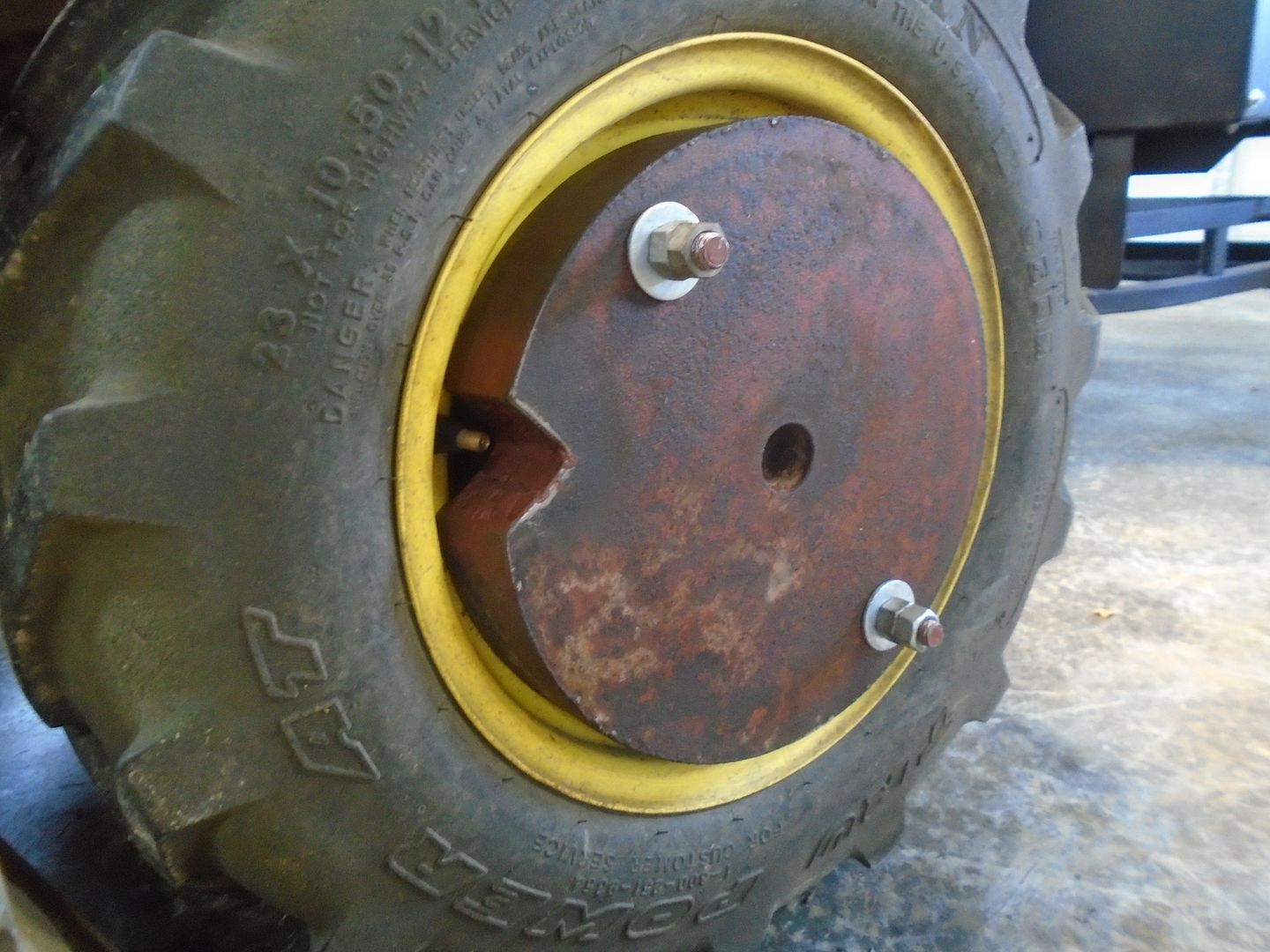
I like to clamp a piece of rubber hose on the bolts to keep them from pushing back out when I slide the weights over them.
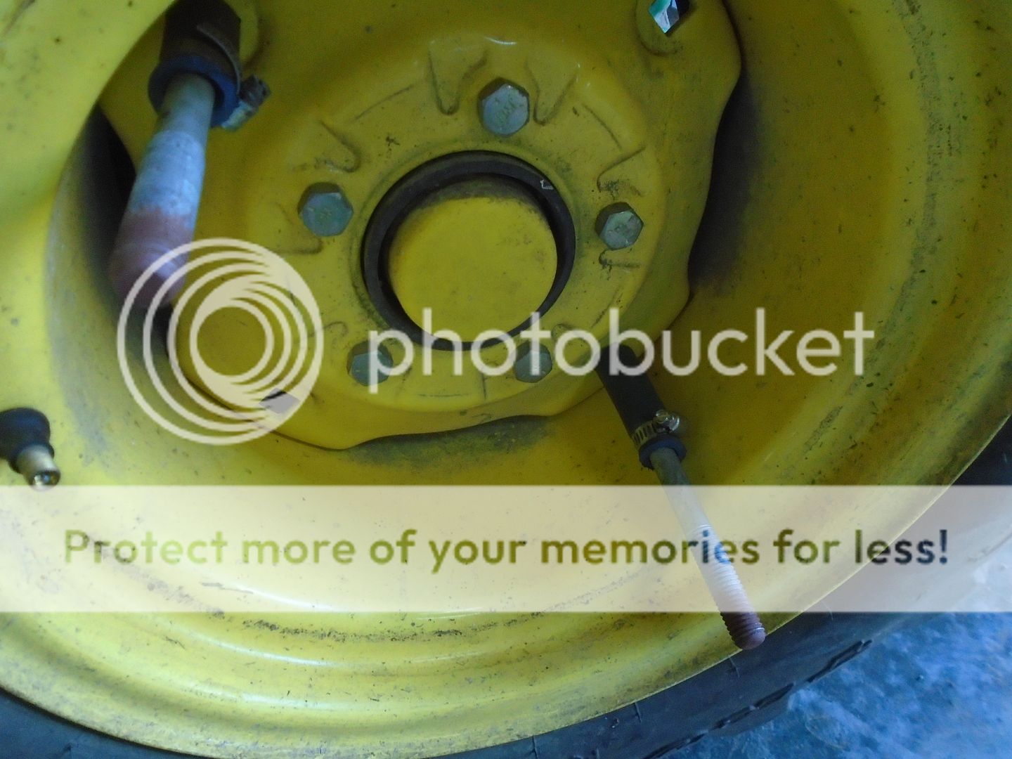
My new wheel weights mounted on the tractor.
I went out and mowed the front yard and the inclined area around the culvert and up by the road ( where the wheel weights are desperately needed ), and the tractor didn't slip once.
You can see the culvert area in the background of the first photo of Marie on the mower.
I didn't weigh them to compare them to the Ridemaster weights, but I think they are heavier then the Ridemaster weights.
Looking thru my photos, this is the only one that I could find of my JD mower.
The rear wheel weights are old Bolens Ridemaster weights and I took them off to use on one of my Ridemasters.

With the weather getting warmer, it is time to start mowing again and there are areas where I need rear weights on the mower.
Some time ago I had picked up a pair of 10 inch diameter by 2 inch thick steel cutouts.
I set one of the Ridemaster weights on top of them and marked where the two bolt holes go and where the notch for the valve stem needs to be.
Then I used the torch to cut out the valve stem notch.

And I put them up on the drill press to drill the holes out to 17/32 ( .03 over the size of the half inch bolts ).

I'm welding three small pieces of angle iron on the inside of each weight to center them in the wheel opening so they don't flop around.

Here is how they look with the three locators welded in place.

I like to clamp a piece of rubber hose on the bolts to keep them from pushing back out when I slide the weights over them.

My new wheel weights mounted on the tractor.
I went out and mowed the front yard and the inclined area around the culvert and up by the road ( where the wheel weights are desperately needed ), and the tractor didn't slip once.
You can see the culvert area in the background of the first photo of Marie on the mower.
I didn't weigh them to compare them to the Ridemaster weights, but I think they are heavier then the Ridemaster weights.

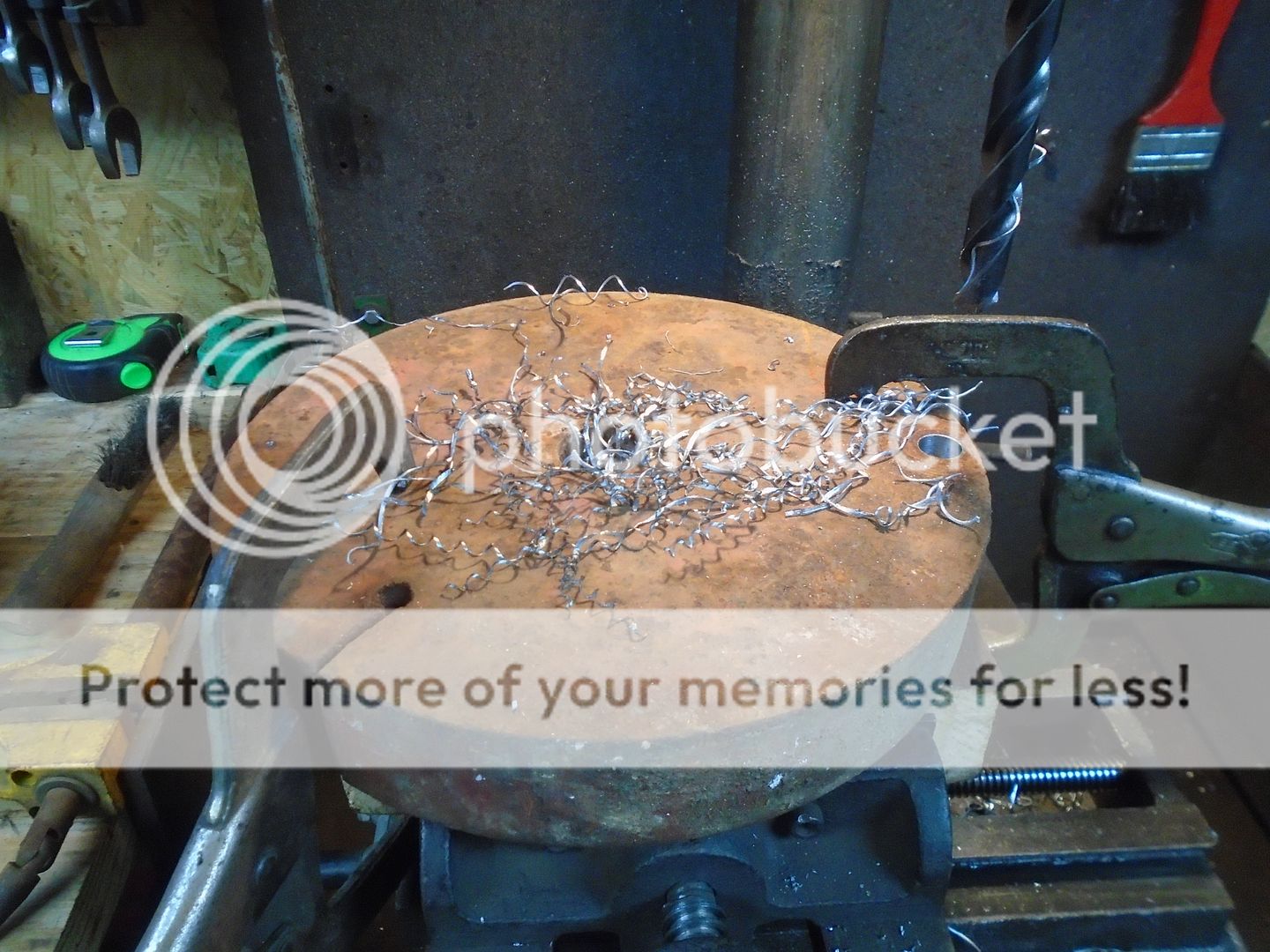
I found two more round steel burnouts that are 9-1/2 inch diameter and 1-1/2 inch thick and I'm going to add them to the weights on the JD.
Here I have just finished drilling one of the holes for the bolts.
These fit down inside the wheel opening.
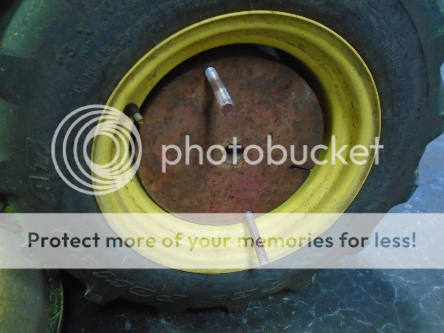
Then the outer weight goes back on.
Here I have just finished drilling one of the holes for the bolts.

These fit down inside the wheel opening.

Then the outer weight goes back on.